Help me identify the issue....
Posted by drmaestro
|
Help me identify the issue.... March 10, 2016 05:27PM |
Registered: 9 years ago Posts: 330 |
Hi.
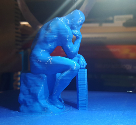
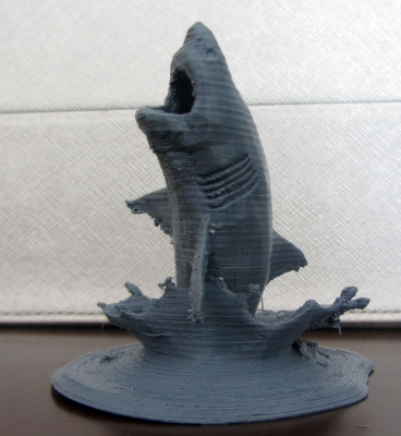
Could you help me identify a print issue I have? For a long time I've fought with z-wobble issues due to a slightly bent threaded rod and also tried to find the best coupling option for the motor. I've since replaced my motor and rod system with one which has a threaded rod directly coming out of the motor (those sold on robotdigg). This solved the problem with the bent rod and couplings but I still haven't been able to achieve perfect prints, as you can see from the picture.
I can't really understand what the actual problem is. Some parts of the print are very good, like the head and the upper parts of the shoulders of the statue. But some other parts tend to bulge out or are not uniform, like the line which is protruding at the shoulder, or the lines at the stone the statue is sitting on, or more prominently, on the support structure. I don't think this is due to z wobble. It doesn't seem to have a periodicity.Could it be uneven extrusion? Some kind of setup issue with Z steps? I'd really appreciate some comments on the issue.
Thank you very much.
|
Re: Help me identify the issue.... March 10, 2016 06:35PM |
Registered: 9 years ago Posts: 978 |
I don't think it's your Z steps... if it was, it would apply across the object, perhaps in bands.
It would be worth observing the printer in action at those pieces. It's a bit hard to tell from the photo, but I think the errors are only in one axis (Y, looking into the screen) and not in X (across the screen)?
If the outer layers of the chest are printed in opposite directions on alternating layers (i.e. one layer is printed clockwise, the next counter-clockwise) then play in the Y axis could create that pattern. If the upper parts of the shoulder are all printed in the same direction, that would explain the absence of apparent errors on those layers. The errors are still there, but they're all in the same direction, so not noticeable. Imagine if printing a vertical cylinder... the nozzle should move in a circle at each layer. On one side of the circle, the Y axis movement is positive, the other side it is negative. At the 'front' of the circle, the Y changes direction from positive to negative, and at the 'back' side it changes back again. At these front and back points, the Y motor will move but, due to the play in the Y axis, the nozzle itself won't move, causing the "circle" to be slightly distorted. Now, if the next layer is printed in the opposite direction (which some slicers do), that layer will be distorted the other way. So you end up with a banded appearance.
What's more, I discovered (after much head-scratching) that play in the Z axis can cause errors in the X or Y axes, if you are using auto-leveling, and depending on the path of the print head. What happens is that, to compensate for the slope of the bed, the Z axis needs to move up or down as the head moves in the X or Y axis. Again, imagine if printing a nominally vertical cylinder on a sloping bed... the nozzle should move in a circle at each layer, in the same plane as the bed's plane. On one side of the circle, the nozzle is moving upwards, the other side it is moving downwards. At the 'high' side of the circle, the Z changes direction from up to down, and at the 'low' side it changes back again. In these areas, the Z motor will move but, due to the play in the Z axis, the head itself won't move up or down, causing the circle to be distorted. Again, you'll get a banded appearance if the next layer is printed in the opposite direction because that layer will be distorted the other way.
So (long story short), I'd suggest checking the tightness of your belts, and the Z-axis coupler, and the belt pulleys on the motor shafts. And all your nuts and bolts.
|
Re: Help me identify the issue.... March 12, 2016 11:09AM |
Registered: 9 years ago Posts: 330 |
Hi,
Thanks for the detailed answer.
The error happens in both axes (it isn't limited to X or Y).
I use Simplify3D as slicer software. The outer and inner layer are both printed in the same direction.
I don't use auto-leveling.
I did tighten my belt system. I don't have a Z axis coupler in my actual construction, as the threaded rod is incorporated inside the stepper itself.
I printed the same object again. I have the same errors, some of them are less pronounced, but they are exactly at the same spots.
|
Re: Help me identify the issue.... March 12, 2016 02:06PM |
Registered: 9 years ago Posts: 1,873 |
It's an interesting print, I gave it a go. Shame there isn't more detail in the hands and feet. The smooth surfaces of the model are very unforgiving for showing up any layer misalignment. I thought my printer was working reasonably well, but my print looks very similar to yours. It was one of my first tries with a smaller layer height, I used 0.12mm, and I think that may not have helped. It's quite a difficult print with some fairly extreme overhangs in places, but quite strangely, even a bad print captures some of the remarkable quality of the original work. I was only planning on using the printer for functional parts, but this might just tempt me to try and collect a few of the scanned art works that are available, and see if I can post-process them to an acceptable finish.
|
Re: Help me identify the issue.... March 12, 2016 02:34PM |
Registered: 9 years ago Posts: 978 |
Quote
drmaestro
The outer and inner layer are both printed in the same direction.
Just to clarify: My comment wasn't related to outer & inner perimeters. I was talking about the outer perimeters of adjacent layers. If they are printed in different directions, then play in the axes can cause banding.
If outer and inner perimeters were in opposite directions, and there was play in the axes, then there could be gaps between those two perimeters, but they wouldn't be visible in the model.
A thought... is your layer height an integral number of Z steps? See the Optimal layer height for your Z axis section of RepRap Calculator
|
Re: Help me identify the issue.... March 14, 2016 04:36PM |
Registered: 9 years ago Posts: 330 |
|
Re: Help me identify the issue.... March 14, 2016 05:17PM |
Registered: 9 years ago Posts: 330 |
I wanted to add another picture:
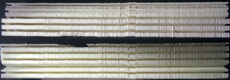
This is the picture of a very tall support structure generated by Simplify3D. I took a photo of the support from the left side (upper part of the photo) and from the right side (lower part of the photo) and composed them as a single picture. I've also used a light source nearly paralelle to the support to accentuate the irregularities on the layers.
What I can observe is:
1) Some layers seem to be misaligned on the Y axis (antero-posterior direction). Some of these misalignments are very subtle, some more pronounced. There doesn't seem to be a definitive periodicity but there are short segments where there is no misalignment and some segments where it is more pronounced.
2) Some layers seem to be bulging in each direction. This is interesting as it would probably imply a problem with irregular Z height. Could the Z motor be missing steps occasionally?
Thanks..
|
Re: Help me identify the issue.... March 14, 2016 10:08PM |
Registered: 8 years ago Posts: 916 |
You've definitely got some slop in there somewhere. I'd grab the nozzle and see if it clicks or wobbles as you shake it around (with the motors locked, like after you command it to go somewhere). Chances are you'll feel the click and be able to see where it's moving. It doesn't look like Z or extruder issues to me, it looks mechanical like if you haven't locked your hotend down properly to your extruder carriage.
Good luck finding it.
Good luck finding it.
|
Re: Help me identify the issue.... March 16, 2016 10:38AM |
Registered: 8 years ago Posts: 183 |
|
Re: Help me identify the issue.... March 19, 2016 07:01AM |
Registered: 9 years ago Posts: 330 |
|
Re: Help me identify the issue.... March 26, 2016 05:31AM |
Registered: 8 years ago Posts: 4 |
|
Re: Help me identify the issue.... March 26, 2016 11:11AM |
Registered: 9 years ago Posts: 330 |
|
Re: Help me identify the issue.... March 29, 2016 01:52AM |
Registered: 8 years ago Posts: 89 |
|
Re: Help me identify the issue.... March 29, 2016 05:09AM |
Registered: 9 years ago Posts: 330 |
Fast movements of the extruder (especially when making infills) might shake the table the printer is on (what I mean by "shake" is if I put a glass of water on the table, I can see ripples forming). I don't see the printer vibrate or shake. I've reduced acceleration values so that my printer doesn't make sudden movements. I am not sure this would cause a similar problem, as it happens layer by layer. It should have been more random if it was due to the vibration of the table.
|
Re: Help me identify the issue.... March 29, 2016 05:44AM |
Registered: 11 years ago Posts: 973 |
0n the pulley motors are the grub screws tight to a flat on the motor shaft?
Check my rubbish blog for my prusa i3
up and running
[3dimetech.blogspot.co.uk]
Check my rubbish blog for my prusa i3
up and running
[3dimetech.blogspot.co.uk]
|
Re: Help me identify the issue.... April 01, 2016 09:29AM |
Registered: 9 years ago Posts: 330 |
Quote
chris33
0n the pulley motors are the grub screws tight to a flat on the motor shaft?
Yes, they are. The motor that is controlling the X axis movement is pılle a little bit due to the tightness of the GT2 belt. This slight gradient forces the belt to the upper part of the pulley but it doesnt't miss a step.
|
Re: Help me identify the issue.... April 01, 2016 11:11AM |
Registered: 8 years ago Posts: 356 |
I had those imperfect walls like the first picture when I build my printer, it turn out to be not tight enough belts, there were pretty tight first time but I still tight them more till a guitar tuner just barely register them as G note for a meter long belts pinch in the middle.
Maybe you should try to tight them more see if this help , if not relax them again
Maybe you should try to tight them more see if this help , if not relax them again
|
Re: Help me identify the issue.... April 25, 2016 07:25PM |
Registered: 9 years ago Posts: 330 |
Hi,
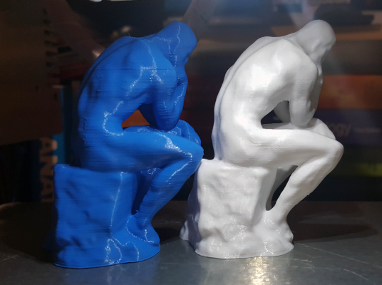
I wanted to post a follow-up on my problem. I've taken into consideration many of the advices provided and made some changes to my printer and settings. First, let me show you the final result:
The left one is the original, and the right one is printed after the modifications. As you can see, most of my problems are gone I'll list the steps I've followed, so that other people with similar problems can learn from my mistakes (and also any comment is appreciated).
Here are the steps I have followed:
1) I always assumed that my rods were parallele, because they seemed to be. Well, they weren't parallele at all. Digital_dentist had advised me to use linear rails, and I intend to in the near future when I find suitable rails and make changes to the Z elevators, but for an easiser alternative, I've changed my rods with longer ones, and used metallic rod holders to fix them to the upper and lower aluminum extrusions (as advised by MechaBits).This step took really a long time, as without fully supported rods or rails, it is nearly impossible to align everything, but right now, I can move the elevators all the way up form the lowest position without feeling any blockage at the bearings.I can check this by not tightening the bolts used on rod holders. If I am able to move the rods freely while the carriage moves up and down, and this means that the carriage moves in a striaght path.
2) I tried to replace all of the idlers with metallic ones (plastic ones couldn't resist the force applied by the GT2 belts).
3) I replaced the SCe8UU bearings used for the Y carriage. There was quite a resistence to the movement and replacing the bearings made a huge difference for the ease of movement. I also had to check the holes on the metallic Y carriage used for fastening the bearings. These holes were not evenly spaced so if I tried to fasten all bearings with 16 bolts, the rails wouldn't slide easily. I've only tightened the aligning holes and left the other ones untightened.
4) I have reprinted Wade's extruder's big gear It did have some resistence at a certain location and I don't know if it was important, but reprinted anyhow. One change that I made here had a big influence on the final print quality: I wasn't tightening the nut holding the hobbed bolt (and the big gear) in place, because if I did so, it did show some resistence while rotating. However, this probably created some backlash, as I could move the gear with my hand for a very short distance (mayba half a milimeter) without the small gear turning. Tightening it solved (or probably minimised) this backlash.
5) I have changed my printing surface. I was using mirror covered with masking tape/Kapton and was assuming I had good adhesion. I have replaced the mirror with GeckoTek3D's metallic printing surface and also used ColorFabb's nGen instead of PLA (my usual material of choice). This had a huge impact, as I didn't need to squash the first layer to have good adhesion. This surface (which is activated by heat) can adhere even with a very small contact area, so I have very flat and regular layers now. Some small supports which were impossible to print without a raft are sticking easily now and they are really easy to remove when the bed cools down. nGen can be quite brittle but it doesn't warp or curl, so that's a huge plus.
6) I have changed my slicing settings. If I use Slicer, I use autospeed. If I use Simplify3D, I set all of the movement speeds (perimeters, infills, supports, etc) to the same value and also use minimal retraction values. I try to maintain a constant pressure at the nozzle and setting the same speeds helps for this purpose.
So, this is a summary of what I did.I think numbers 1 and 4 were the most important ones. Right now I am happy with the results and I feel like I've upgraded to a high resolution system, as I can see details that were impossible to create with my previous setup. Thank you very much for all of the suggestions.
Edited 3 time(s). Last edit at 04/26/2016 06:24AM by drmaestro.
I wanted to post a follow-up on my problem. I've taken into consideration many of the advices provided and made some changes to my printer and settings. First, let me show you the final result:
The left one is the original, and the right one is printed after the modifications. As you can see, most of my problems are gone
 I'll list the steps I've followed, so that other people with similar problems can learn from my mistakes (and also any comment is appreciated).
Here are the steps I have followed:
1) I always assumed that my rods were parallele, because they seemed to be. Well, they weren't parallele at all. Digital_dentist had advised me to use linear rails, and I intend to in the near future when I find suitable rails and make changes to the Z elevators, but for an easiser alternative, I've changed my rods with longer ones, and used metallic rod holders to fix them to the upper and lower aluminum extrusions (as advised by MechaBits).This step took really a long time, as without fully supported rods or rails, it is nearly impossible to align everything, but right now, I can move the elevators all the way up form the lowest position without feeling any blockage at the bearings.I can check this by not tightening the bolts used on rod holders. If I am able to move the rods freely while the carriage moves up and down, and this means that the carriage moves in a striaght path.
2) I tried to replace all of the idlers with metallic ones (plastic ones couldn't resist the force applied by the GT2 belts).
3) I replaced the SCe8UU bearings used for the Y carriage. There was quite a resistence to the movement and replacing the bearings made a huge difference for the ease of movement. I also had to check the holes on the metallic Y carriage used for fastening the bearings. These holes were not evenly spaced so if I tried to fasten all bearings with 16 bolts, the rails wouldn't slide easily. I've only tightened the aligning holes and left the other ones untightened.
4) I have reprinted Wade's extruder's big gear It did have some resistence at a certain location and I don't know if it was important, but reprinted anyhow. One change that I made here had a big influence on the final print quality: I wasn't tightening the nut holding the hobbed bolt (and the big gear) in place, because if I did so, it did show some resistence while rotating. However, this probably created some backlash, as I could move the gear with my hand for a very short distance (mayba half a milimeter) without the small gear turning. Tightening it solved (or probably minimised) this backlash.
5) I have changed my printing surface. I was using mirror covered with masking tape/Kapton and was assuming I had good adhesion. I have replaced the mirror with GeckoTek3D's metallic printing surface and also used ColorFabb's nGen instead of PLA (my usual material of choice). This had a huge impact, as I didn't need to squash the first layer to have good adhesion. This surface (which is activated by heat) can adhere even with a very small contact area, so I have very flat and regular layers now. Some small supports which were impossible to print without a raft are sticking easily now and they are really easy to remove when the bed cools down. nGen can be quite brittle but it doesn't warp or curl, so that's a huge plus.
6) I have changed my slicing settings. If I use Slicer, I use autospeed. If I use Simplify3D, I set all of the movement speeds (perimeters, infills, supports, etc) to the same value and also use minimal retraction values. I try to maintain a constant pressure at the nozzle and setting the same speeds helps for this purpose.
So, this is a summary of what I did.I think numbers 1 and 4 were the most important ones. Right now I am happy with the results and I feel like I've upgraded to a high resolution system, as I can see details that were impossible to create with my previous setup. Thank you very much for all of the suggestions.
Edited 3 time(s). Last edit at 04/26/2016 06:24AM by drmaestro.
|
Re: Help me identify the issue.... April 25, 2016 09:14PM |
Registered: 9 years ago Posts: 1,873 |
|
Re: Help me identify the issue.... April 25, 2016 10:43PM |
Registered: 8 years ago Posts: 778 |
|
Re: Help me identify the issue.... April 26, 2016 04:38AM |
Registered: 8 years ago Posts: 15 |
|
Re: Help me identify the issue.... April 26, 2016 02:21PM |
Registered: 9 years ago Posts: 330 |
I'll add some photos as requested by NikosK:
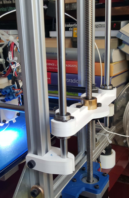
1) The first step was about the smooth rods. Here is a picture of my previous setup:
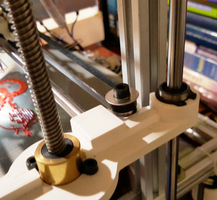
As you can see, the rods are held by plastic holders, attached to the vertical extrusions. In theory, using the vertical extrusion should help with parallelity, but the plastic parts didn't fit in a firm manner and also they could tilt a little bit up or down, so the rod was not completely vertical. I have changed the plastic holders with metal ones and used longer rods:
I can't really say that is a better solution for the parallelity issue, as it isn't a fully supported rod or rail but it is a more adjustable setup, so you can move the upper or lower holders to make them parallele.
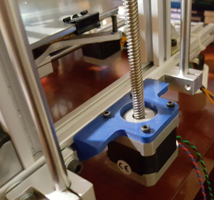
I should also mention that I am using a motor with a leadscrew as rod:
This is something I've changed a few months ago and I can say that it had an immense effect on my prints. Look at the wooble I had when I was using threaded rods with couplings:
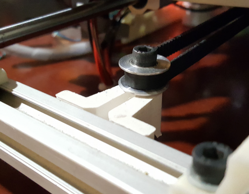
2) The metallic idlers: I had plastic ones and they tended to crack under pressure. I've changed them with metal ones. There are 2 types of idlers: With or without teeth. I don't know if choosing one over the other makes a difference in print quality:
The one on the first picture has teeth, the second doesn't have them.
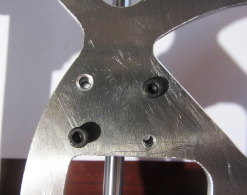
3) Changing the bearings. The bearings are very important for the smooth movement of the carriages. When I've built the printer 2 years ago, I didn't have a lot of technical info on different parts, so I didn't treat them as I should have: The bearings should stay in their packaging until you are ready to use them. If you take them out, start playing with them by inserting and removing rods, and leaving them unprotected overnight, they gather dust. This dust is very difficult to get rid of, so my old setup had movement problems. I have replaced the bearing with new ones, beaing careful not to dislocate the small balls inside (they can dislocate very easily if you force the rod in). Also, my Y carriage is made of metal but the holes for fastening the bearings were not symmetrical:
Look at the holes; they are not aligning with the bearings. I tried to use as many bolts as I could in my previous setup, but now I didn't force them. Because, if you do, it is possible to change the direction of the bearing and even a very small amount of change has a huge impact on the free movement of the bearing.
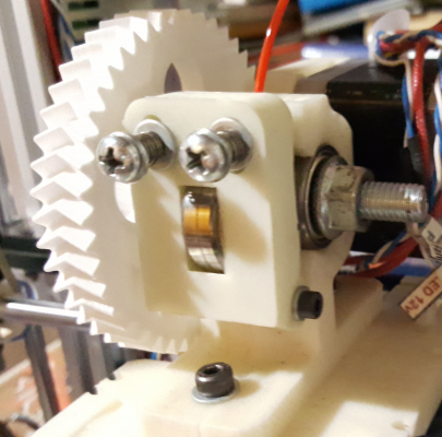
4) For the extruder, here's a picture:
I have printed the big gear and also tightened the M8 flanged nut that you can see on the picture. It halped with the backlash.
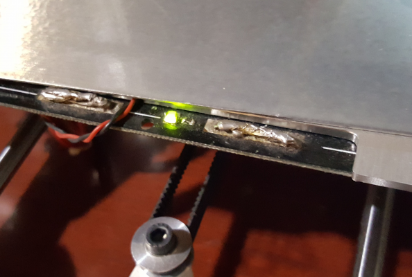
5) I am using the GeckoTek3D build platform now. It is very good for printing with nGen. It is supposed to be good for ABS also but I don't print with ABS, so I can't comment on this. I can also print with PLA but I can't get the very smooth layers I get with nGen. Probably a problem with Z height. Just a warning:
If you have never used metal printing surfaces, you should be very very careful with them, as they are conductive unlike mirror or glass. The first time I've installed the plate, I shorted the heated bed's wires (as you can see, they are very easy to short, as they are bulging). I should insulate them in the near future.
6) I am not attaching a picture for the slicing settings but as I've said, I am setting the same movement speed in Simplify3D ans using autospeed in Slicer.
|
Re: Help me identify the issue.... April 26, 2016 09:57PM |
Registered: 8 years ago Posts: 778 |
The pic really help to visualise everything -great job!
One suggestion for your problem of paralellity:
Currently you use a quite thin block to hold the x-axis on the smooth rods.
If you design them as a double so to speak you can use one smooth roller on the top and on the bottom of each side of the mounts.
Same story for the nut on the threaded rod.
In my setup there is a quite strong spring on top of the nut, the nut itself is in a hexagonal hole to allow it to move up and down about 5mm.
In the top is a second nut which is fixd in place.
What this does:
The two linear bearings on each side ensure that the mount stays parallel onto the rods without any noticable play in movement.
The double nut system with the spring makes sure there is no play left in the z-direction - check a normal nut on a bot and you will feel it can wobble a bit.
Together the system still allows to compensate for accidents like blobs on the print without the risk of something getting out of alignment.
As for the wrong holes for the bearings:
In some setups these metal brackets can be mounted in two ways - it might be worth flipping them to check the hole alignment.
Usually they are drilled with a template and it is possible the template is not as even as it should.
The other way to get proper support for the bearings is by cheating.
(Was a skater in my young years)
The position for the bearings is fixed so you need to make the existing holes to align with them using a round file or similar.
It is enough to mark the approximate hole and to file it slightly bigger to be on the safe side and allow for a tiny bit of play.
Depending on the gap between the bearing and mount you need one or more bearing washers - they are thinner than normal washers and perfectly fit the inner ring of the bearing.
These allow the inner ring to be fixed without disturning the balls or moving parts.
If the gap is bigger you can add normal washers, just keep one bearing washer right at the inner ring from both sides of the bearing.
You can now fasten the bolt and the bearing will determine where the thing will get stuck in the frame.
So instead of forcing the bearing into the hole you forced a bolt to support the bearing free of any side loads

|
Re: Help me identify the issue.... April 30, 2016 05:38PM |
Registered: 8 years ago Posts: 41 |
Sorry, only registered users may post in this forum.
