straight vertical perimeter starting points?
Posted by panire
|
straight vertical perimeter starting points? March 15, 2016 11:48AM |
Registered: 8 years ago Posts: 6 |
Dear Community 
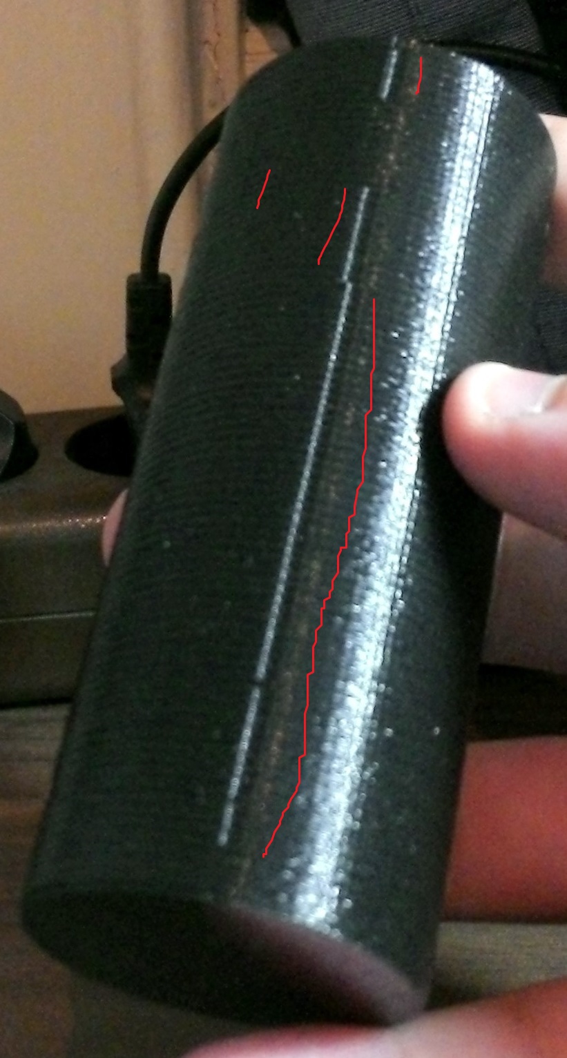
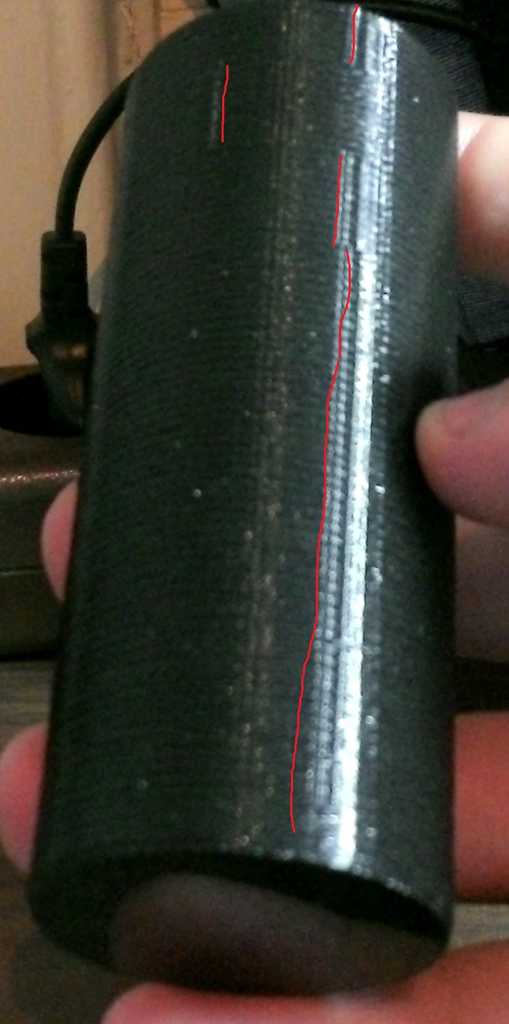
Is there a way to always start the perimeters on the same vertical position (i cant get them aligned - see images)?
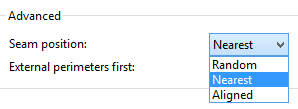
I tried the advanced settings (seam position: nearest, random aligned), but this options dont get it righ. quite well.
Thanks for a short suggestion (a link would also be ok, as i seem to bee too stupid to find information about that yet).
Greetings and thank you
Edited 1 time(s). Last edit at 03/15/2016 11:48AM by panire.
Is there a way to always start the perimeters on the same vertical position (i cant get them aligned - see images)?
I tried the advanced settings (seam position: nearest, random aligned), but this options dont get it righ. quite well.
Thanks for a short suggestion (a link would also be ok, as i seem to bee too stupid to find information about that yet).
Greetings and thank you
Edited 1 time(s). Last edit at 03/15/2016 11:48AM by panire.
|
Re: straight vertical perimeter starting points? March 15, 2016 12:35PM |
Registered: 11 years ago Posts: 5,780 |
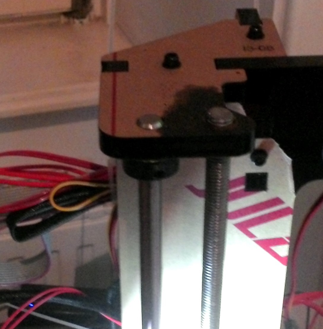
In the first picture I think I am seeing pretty severe Z wobble- or was that an intentional part of the design?
In the rest I see the seam moving around- if you print just a cylinder or cube and do not change anything from top to bottom- that means no changes in area/size of anything, variations in infill density or pattern, etc.- it should keep the seam in a straight line. As soon as anything about the shape changes, the gcode planner changes the tool path and the location of the layer start with it.
I don't believe there is any way in Slic3r to force the seam to a specific position even on the simplest prints.
Ultra MegaMax Dominator 3D printer: [drmrehorst.blogspot.com]
|
Re: straight vertical perimeter starting points? March 15, 2016 12:51PM |
Registered: 8 years ago Posts: 6 |
Ok I see.
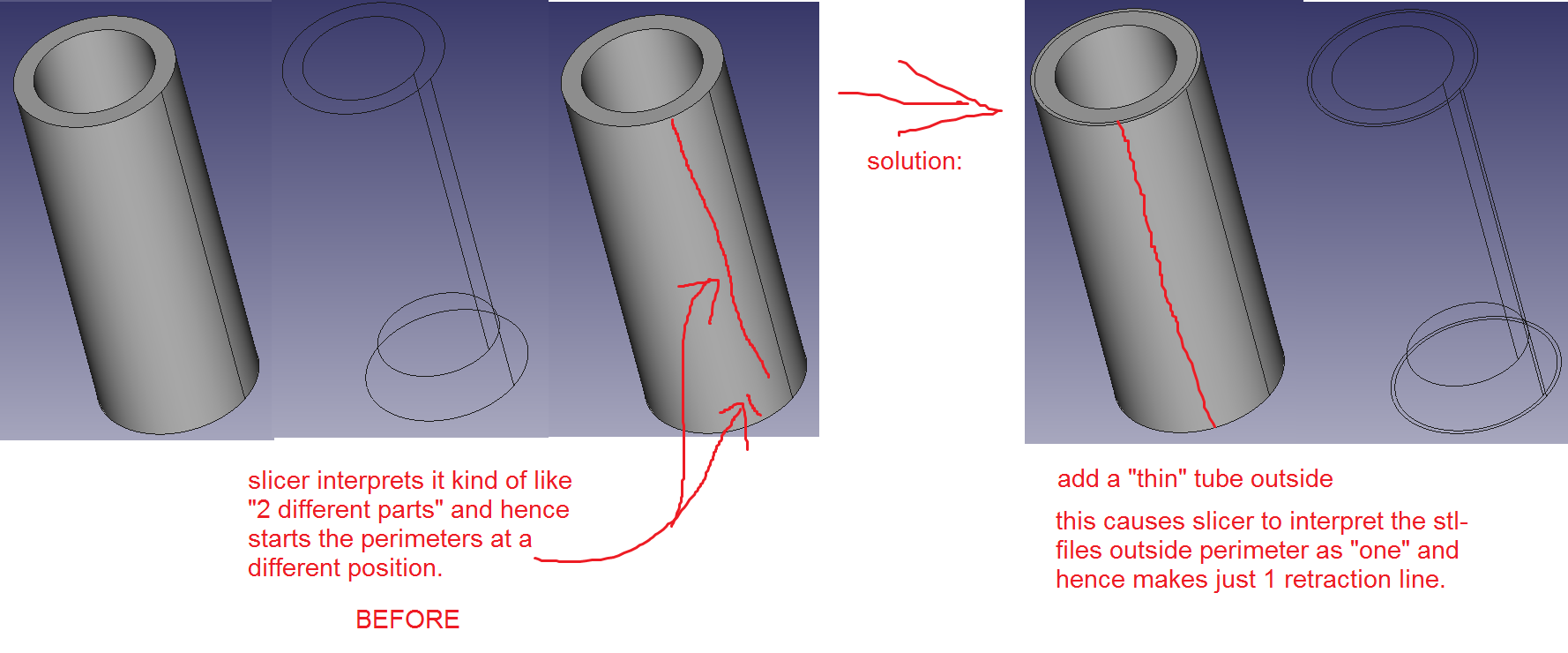
i will try to insert a thin tube as outer layer, so maybe slic3r can interpret it as one object through that.
about the z-axis:
Its printed on a 250$-Geeetech printer for, the z-axis threaded rods doesn't sit that stiff inside theyr threads and they are even a bit bended (i guess thats ok for the priceclass). I still like the print in general, but really thanks for being that exact about it - I will have a look on how to improve that. :-)
thank you
|
Re: straight vertical perimeter starting points? March 15, 2016 03:20PM |
Registered: 8 years ago Posts: 6 |
|
Re: straight vertical perimeter starting points? March 15, 2016 03:23PM |
Registered: 8 years ago Posts: 6 |
|
Re: straight vertical perimeter starting points? March 15, 2016 06:11PM |
Registered: 11 years ago Posts: 5,780 |
Quote
panire
"i will try to insert a thin tube as outer layer, so maybe slic3r can interpret it as one object through that."
yup that was the solution, i added a very thin tube "0.03mm" to the outside, so slicer interpreted it right.
Can you post a screen shot showing what that looks like?
Thanks!
Edited 1 time(s). Last edit at 03/15/2016 06:11PM by the_digital_dentist.
Ultra MegaMax Dominator 3D printer: [drmrehorst.blogspot.com]
|
Re: straight vertical perimeter starting points? March 16, 2016 01:52AM |
Registered: 11 years ago Posts: 973 |
so the threaded rod gather not a proper lead/ball screw is it fixed at the top or open? if its fixed and the thread not perfectly straight, thats why orignal prusa wasnt captive using threaded m5 bar
Check my rubbish blog for my prusa i3
up and running
[3dimetech.blogspot.co.uk]
Check my rubbish blog for my prusa i3
up and running
[3dimetech.blogspot.co.uk]
|
Re: straight vertical perimeter starting points? March 16, 2016 01:01PM |
Registered: 8 years ago Posts: 6 |
"Can you post a screen shot showing what that looks like?"
Have a look - attachment
I have no idea how slicer reads the stl-file. i am sure its highly dependent on the way of how the stl file is read.
in this case i exported the stl file from freecad.
Edited 1 time(s). Last edit at 03/16/2016 01:06PM by panire.
Have a look - attachment
I have no idea how slicer reads the stl-file. i am sure its highly dependent on the way of how the stl file is read.
in this case i exported the stl file from freecad.
Edited 1 time(s). Last edit at 03/16/2016 01:06PM by panire.
|
Re: straight vertical perimeter starting points? March 16, 2016 01:17PM |
Registered: 8 years ago Posts: 6 |
Quote
chris33
so the threaded rod gather not a proper lead/ball screw is it fixed at the top or open? if its fixed and the thread not perfectly straight, thats why orignal prusa wasnt captive using threaded m5 bar
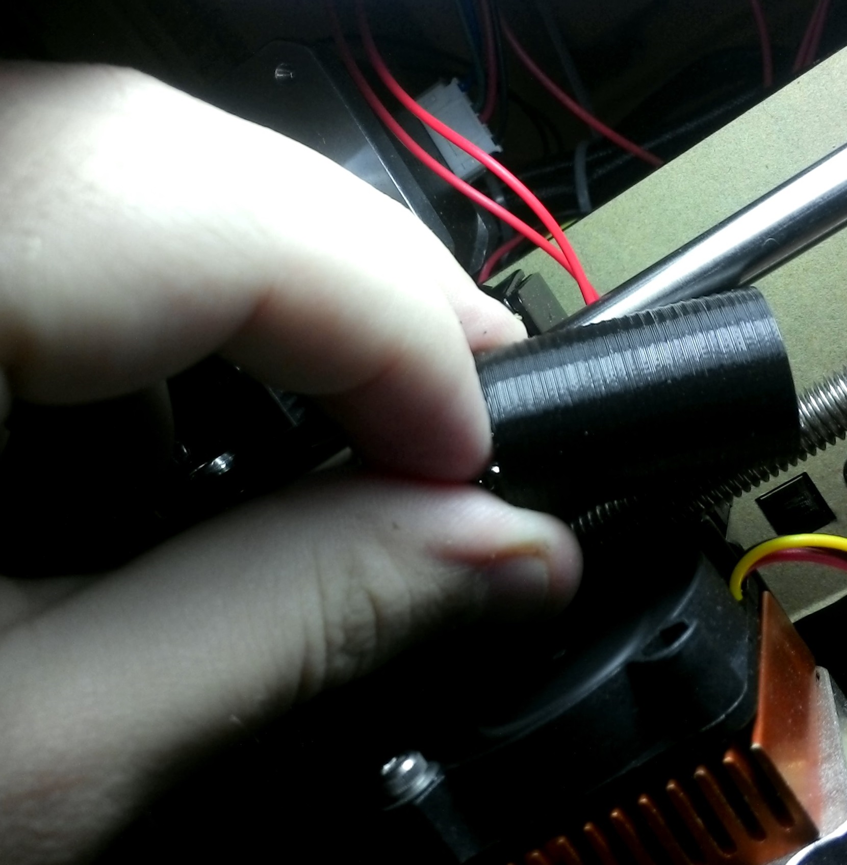
The wobble has quite the same size like the threads itself.
Its not really free, it touches the acrylic a bit. shall I make the hole of the acrylic bigger so the threaded rod hangs free?
Edited 1 time(s). Last edit at 03/16/2016 01:19PM by panire.
Sorry, only registered users may post in this forum.