My extruder under/over extrudes depending on speed, even at low speeds. I'm very confused.
Posted by geofox784
|
My extruder under/over extrudes depending on speed, even at low speeds. I'm very confused. December 25, 2017 12:09AM |
Registered: 6 years ago Posts: 4 |
Problem:
I have been messing with this all day and have not been able to figure it out. My extruder flow rate seems to vary a fair amount depending on speed. I would expect this if there was grinding or steps being skipped, but I can not detect either visually. I have also marked the gear on the extruder, so I know 100% steps are not being skipped. I don’t see any evidence of grinding on the hob (its clean).
I had this happen on my old extruder as well, an entirely different design with different hardware. Maybe this is a common problem I am over thinking?
It seems like flow rate should be constant depending on speed up to when it starts grind. It definitely should not be grinding between .5mm/s and 1mm/s, but there is still a noticeable difference in measured flow rate.
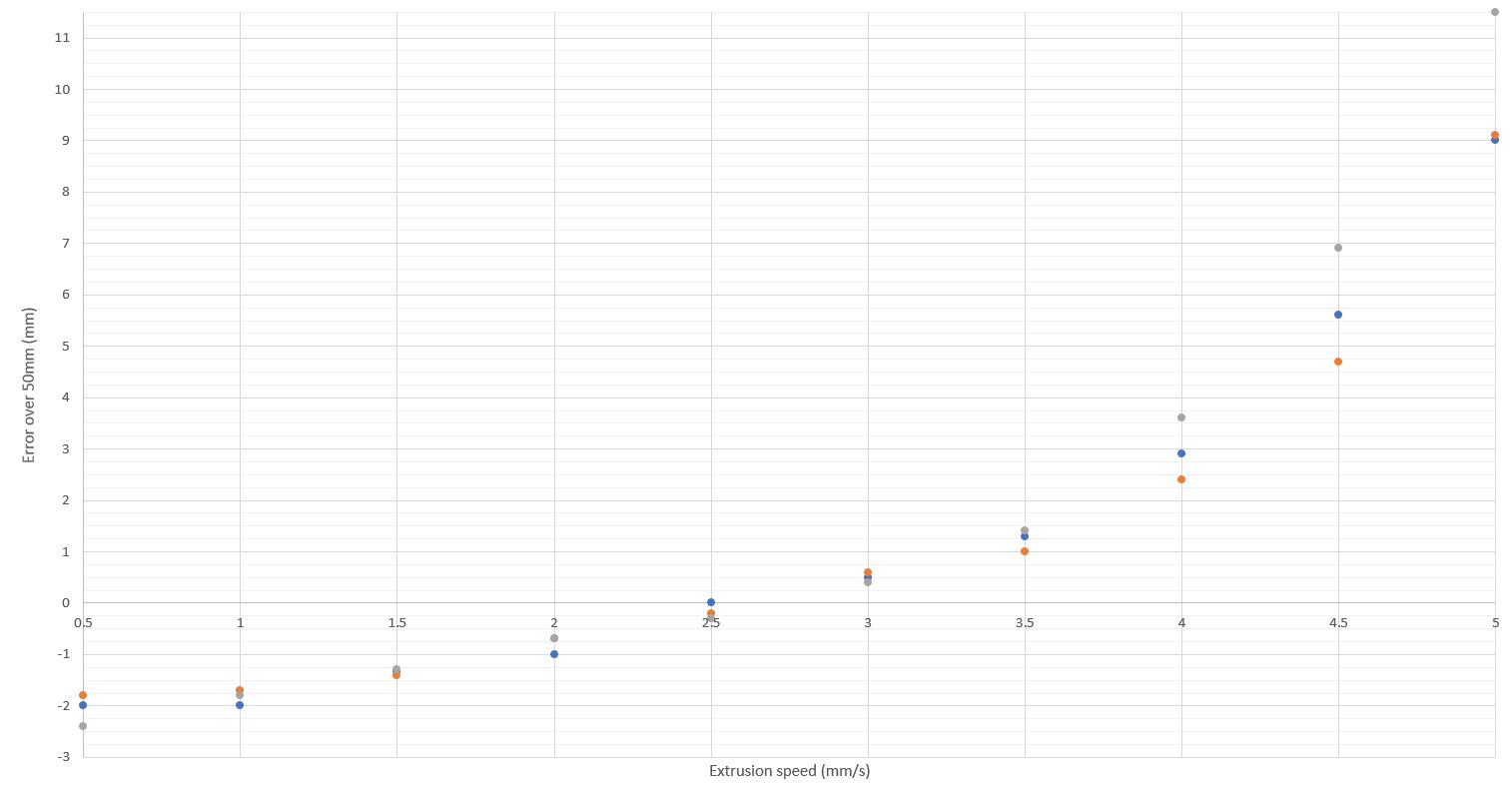
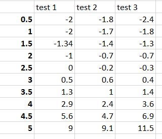
To test this, I measure and mark the filament at 60mm, then extrude 50mm. After that I measure the distance from 10mm. I measure each speed from .5mm to 5mm, then repeated the whole set 3 times.
Specs:
E3D titan with hardened hob
Tightness at either mid or max. Doesn’t make a difference.
E3D v6
Test done at 200C. 210C didn’t seem to help.
My questions:
Any ideas as to what is going on?
Are prints not that sensitive to this, so if I print at max 3.5 mm/s I should be fine?
Could some others do the same test, at least at two different speeds, to see if it is a common problem?
What is the max flow rate you can push before you start to have problems?
Thanks for the help!
I have been messing with this all day and have not been able to figure it out. My extruder flow rate seems to vary a fair amount depending on speed. I would expect this if there was grinding or steps being skipped, but I can not detect either visually. I have also marked the gear on the extruder, so I know 100% steps are not being skipped. I don’t see any evidence of grinding on the hob (its clean).
I had this happen on my old extruder as well, an entirely different design with different hardware. Maybe this is a common problem I am over thinking?
It seems like flow rate should be constant depending on speed up to when it starts grind. It definitely should not be grinding between .5mm/s and 1mm/s, but there is still a noticeable difference in measured flow rate.
To test this, I measure and mark the filament at 60mm, then extrude 50mm. After that I measure the distance from 10mm. I measure each speed from .5mm to 5mm, then repeated the whole set 3 times.
Specs:
E3D titan with hardened hob
Tightness at either mid or max. Doesn’t make a difference.
E3D v6
Test done at 200C. 210C didn’t seem to help.
My questions:
Any ideas as to what is going on?
Are prints not that sensitive to this, so if I print at max 3.5 mm/s I should be fine?
Could some others do the same test, at least at two different speeds, to see if it is a common problem?
What is the max flow rate you can push before you start to have problems?
Thanks for the help!
|
Re: My extruder under/over extrudes depending on speed, even at low speeds. I'm very confused. December 25, 2017 08:39AM |
Registered: 11 years ago Posts: 5,780 |
What are you trying to achieve? Are you trying to solve a printing problem? Calibrate the extruder?
When the machine is printing, the controller is working to extrude a specific amount of filament at a variable rate, taking into account line width, nozzle diameter, layer thickness, print speed, acceleration, and jerk in the mechanism and acceleration in the extruder. It runs the motor as needed to get the output needed. If it misbehaves while printing, it's usually not too hard to diagnose the problem by looking at the print. Measuring the filament going into the extruder as it squirts plastic into the air is interesting, but I don't know what it will tell you.
Ultra MegaMax Dominator 3D printer: [drmrehorst.blogspot.com]
|
Re: My extruder under/over extrudes depending on speed, even at low speeds. I'm very confused. December 25, 2017 10:11AM |
Registered: 6 years ago Posts: 4 |
|
Re: My extruder under/over extrudes depending on speed, even at low speeds. I'm very confused. December 25, 2017 11:37AM |
Registered: 11 years ago Posts: 5,780 |
Many people think that setting steps per mm by measuring the filament moved constitutes calibrating the extruder. It doesn't. It's just the starting point.
The goal of calibrating the extruder is to get it to lay down a specified line width at a specified layer thickness, while it is printing. Calibration of the extruder is usually started without the hot-end attached. You do as you are doing to get a rough steps/mm value to use (or just use the manufacturer recommended value as a starting point, if there is one) then you fine tune it using test prints.
Before you start making test prints, you have to understand that the old programmer's expression garbage-in - garbage-out applies to extrusion. Unless the slicer knows the actual diameter of the filament being used to calibrate, the calibration will be meaningless. If the slicer uses the default 1.75 mm diameter and the filament isn't that diameter, it isn't going to extrude the correct amount of filament. So, the very first thing to do when running calibration test prints is to measure the filament diameter in multiple places (20-30) and calculate an average diameter and use that average diameter when slicing for calibration.
I like Triffid Hunter's calibration procedure- it works. Don't skip the fine e-steps calibration.
Once the extruder is calibrated, there are two ways to ensure that your prints come out with consistently high quality from one spool of filament to another. You can use the average filament diameter (which varies from one spool to the next) or use extruder flow control to compensate for spool to spool differences in filament diameter. If you want to use the filament diameter method, you use the calculated average filament diameter of each spool and mark it on the spool. It takes a couple minutes to measure and calculate the average. For critical prints, use that average diameter when you slice or when you print (if you're using volumetric extrusion). If you prefer to use extruder flow control, you make a test print with each spool, measure the line width, and calculate a flow control value to use that will give the correct line width. Mark the flow control value on the spool for future use.
For noncritical prints, you can just use the nominal 1.75mm diameter (once the extruder has been calibrated, of course) or leave flow control set to 100%.
Ultra MegaMax Dominator 3D printer: [drmrehorst.blogspot.com]
|
Re: My extruder under/over extrudes depending on speed, even at low speeds. I'm very confused. December 25, 2017 11:44AM |
Registered: 6 years ago Posts: 4 |
I agree with the garbage in - garbage out. The problem is that the amount being extruded, even if the extruder drive gear turns the same distance, changes with speed. I read through the fine calibration, and that would change if I was doing the test at a speed resulting in ≈ 1mm/s of filament going into the extruder compared to a speed resulting in ≈ 3mm/s of filament going into the extruder.
|
Re: My extruder under/over extrudes depending on speed, even at low speeds. I'm very confused. December 25, 2017 01:05PM |
Registered: 11 years ago Posts: 5,780 |
The goal of calibrating the extruder is to get it to lay down a specified line width at a specified layer thickness, while it is printing. Calibration of the extruder is usually started without the hot-end attached.
I'm not sure why you're getting different values unless the extruder is skipping steps or the extruder design allows the filament to ride on different parts (diameters) of the drive gear. Is this a Bowden setup? There will be different pressures in the heater block with different extrusion speeds. What counts is not what it does when squirting plastic into the air but what it does when it is printing. The initial test (without the hot-end attached) is done to get steps/mm into the ball-park. Fine adjustment is done based on printing performance. Pick a starting e steps/mm value and move on. It's going to change when you run print tests.
Edited 1 time(s). Last edit at 12/25/2017 01:13PM by the_digital_dentist.
Ultra MegaMax Dominator 3D printer: [drmrehorst.blogspot.com]
|
Re: My extruder under/over extrudes depending on speed, even at low speeds. I'm very confused. December 27, 2017 10:01AM |
Registered: 11 years ago Posts: 5,780 |
I was looking at your chart again. It looks like the extruder is moving more filament at higher speeds and less at lower speeds. Is that right?
Does your controller board happen to have DRV8825 drivers? Those are known to skip steps at low speeds...
Ultra MegaMax Dominator 3D printer: [drmrehorst.blogspot.com]
Does your controller board happen to have DRV8825 drivers? Those are known to skip steps at low speeds...
Ultra MegaMax Dominator 3D printer: [drmrehorst.blogspot.com]
|
Re: My extruder under/over extrudes depending on speed, even at low speeds. I'm very confused. December 27, 2017 11:35AM |
Registered: 6 years ago Posts: 4 |
Quote
I was looking at your chart again. It looks like the extruder is moving more filament at higher speeds and less at lower speeds. Is that right?
The opposite. That is the measurement over 10mm when it started at 60mm.
Quote
Does your controller board happen to have DRV8825 drivers?
Nope. I am 100% certain it is not skipping steps. I marked the gear and it is turning the same amount regardless of speed. There is something going on aside from the motor and electronics. What would be great is if someone else could test this on their setup. Simly tell it to extrude 50mm at your fastest feed rate, and then 50mm at 1mm/s feed rate.
|
Re: My extruder under/over extrudes depending on speed, even at low speeds. I'm very confused. December 31, 2017 01:53PM |
Registered: 10 years ago Posts: 14,672 |
You might be interested in this thread [www.duet3d.com] which describes similar observations made by two users.
What I think is happening is that the higher the back pressure from the nozzle, the more that each tooth on the hobbed shaft compresses and skates over the surface of the filament before it manages to bite into it. If this hypothesis is correct, then you should find that the spacing between teeth marks on filament leaving the extruder reduces as the speed (and hence back pressure) increases.
I can think of two solutions:
1. Use a different type of extruder drive, for example that type that holds the filament between two belts instead of using a hobbed shaft.
2. Compensate for the effect in firmware, by making extruder_drive_speed = f(requested_extrusion_speed) where f(x) = x + ax^2 + bx^3 for some values of a and b. Unfortunately, the ideal values of a and b will almost certainly depend on the filament and the extrusion temperature. However, using a type of filament monitor that measures actual extrusion amount, the calibration cold be done automatically.
I will probably implement #2 in ReprapFirmware because it has been requested and toothed extruders are so popular.
Edited 3 time(s). Last edit at 12/31/2017 02:05PM by dc42.
Large delta printer [miscsolutions.wordpress.com], E3D tool changer, Robotdigg SCARA printer, Crane Quad and Ormerod
Disclosure: I design Duet electronics and work on RepRapFirmware, [duet3d.com].
|
Re: My extruder under/over extrudes depending on speed, even at low speeds. I'm very confused. January 01, 2018 08:04AM |
Registered: 8 years ago Posts: 622 |
My take on it is that it takes time to melt filament. Contact surface area in the melt chamber is probably the most important thing but it still takes time for the heat to transfer from the outer surface of the filament through to the inner core because filament itself is a very poor conductor of heat. In the thread that David linked too, there is a lot of what to my mind is "theoretical twaddle" to do with friction and that melt rate is not in fact a consideration. This is at odds with my own practical testing where I have achieved far higher print speeds using a Diamond hot end which has 3 melt chambers feeding into the same single nozzle, so I have to disagree. At higher speed as one approaches the filament melt rate, pressure builds up because one is then trying to force semi-molten filament through the same size nozzle. Increasing the extrusion rate will simply increase pressure even more. It may offer some degree of compensation but this pressure then has to be dissipated, so for non-print moves, it will likely lead to oozing lead requiring ever higher retraction, and short moves (that don't have to to accelerate up to full print speed), following longer high speed moves will be over extruded as the pressure dissipates.
|
Re: My extruder under/over extrudes depending on speed, even at low speeds. I'm very confused. January 01, 2018 12:30PM |
Registered: 10 years ago Posts: 14,672 |
I agree that using a nozzle system that provides better heat flow to the filament (e.g. Diamond ot Volcano) may reduce back pressure, up to the point at which the filament is fully molten when it enters the nozzle. However, three of us have now confirmed by measurement that even at fairly modest extrusion speeds, the extruder steps/mm increase significantly with increasing extrusion rate when using an ordinary hot end.
You might care to do these measurements on your Diamond hot end, when feeding equal amounts of 3 or 5 filaments into it. The effect may well be smaller than on my single E3Dv6, but it could still be significant.
Edited 1 time(s). Last edit at 01/01/2018 12:30PM by dc42.
Large delta printer [miscsolutions.wordpress.com], E3D tool changer, Robotdigg SCARA printer, Crane Quad and Ormerod
Disclosure: I design Duet electronics and work on RepRapFirmware, [duet3d.com].
|
Re: My extruder under/over extrudes depending on speed, even at low speeds. I'm very confused. January 01, 2018 05:56PM |
Registered: 8 years ago Posts: 622 |
Isn't it about how things print rather then how an extruder behaves under static conditions? I always have to battle over extrusion at the extremities of moves when printing at high speeds which I suspect is due to pressure build up. The last thing I'd want to do is increase the extrusion multiplier.
|
Re: My extruder under/over extrudes depending on speed, even at low speeds. I'm very confused. January 02, 2018 03:11AM |
Registered: 10 years ago Posts: 14,672 |
If we assume that the slicer is doing a good job, it's about getting the extrusion rate (i.e. mm of filament extruded per mm of head motion) to match what the slicer commanded, during all phases of the move, and irrespective of the speed the move gets executed at. Pressure advance aims to correct for under-extrusion during the acceleration segment and over-extrusion during the deceleration segment, but is probably capable of being improved further. Nonlinear extruder drive compensation aims to correct for under-extrusion in high speed moves caused by the filament drive mechanism.
Edited 1 time(s). Last edit at 01/02/2018 03:13AM by dc42.
Large delta printer [miscsolutions.wordpress.com], E3D tool changer, Robotdigg SCARA printer, Crane Quad and Ormerod
Disclosure: I design Duet electronics and work on RepRapFirmware, [duet3d.com].
Edited 1 time(s). Last edit at 01/02/2018 03:13AM by dc42.
Large delta printer [miscsolutions.wordpress.com], E3D tool changer, Robotdigg SCARA printer, Crane Quad and Ormerod
Disclosure: I design Duet electronics and work on RepRapFirmware, [duet3d.com].
|
Re: My extruder under/over extrudes depending on speed, even at low speeds. I'm very confused. January 02, 2018 04:47AM |
Registered: 8 years ago Posts: 622 |
Quote
dc42
If we assume that the slicer is doing a good job, it's about getting the extrusion rate (i.e. mm of filament extruded per mm of head motion) to match what the slicer commanded, during all phases of the move, and irrespective of the speed the move gets executed at. Pressure advance aims to correct for under-extrusion during the acceleration segment and over-extrusion during the deceleration segment, but is probably capable of being improved further. Nonlinear extruder drive compensation aims to correct for under-extrusion in high speed moves caused by the filament drive mechanism.
But we don't know for sure that we have an under extrusion issue under normal printing situations and that if it exists, that it's purely a function of speed. Certainly, on my machine I don't see this under extrusion - merely over extrusion at the end of long high speed moves. I don't see these forums awash with posts by people claiming to experience this phenomenon in "real world" printing scenarios.
I considered doing the static tests but then discounted them as being irrelevant. The reason being that assuming the OP is using a 0.4mm diameter nozzle, the area would be about 0.126 mm^2. The area of 1.75mm diameter filament is about 2.4mm^2 - about 20 times greater. So to extrude 50mm of 1.75 mm diameter filament would require a print move of around 1,000 mm and such moves require a printer with a bed size greater than a metre. Personally, for measurement accuracy, I generally extrude about 100mm of filament so in my case, I'd need a bed size of over 2,000 mm to see that amount of filament extruded in a single move.
One big issue that I have is that this theory is based on the unproven assumption that there is a linear relationship between speed and extruded filament behaviour. What if that's not true? What if it takes time for pressure to build up and lead to this under extrusion? What if the first 25mm of the OPs filament is extruded at normal speed and it's only after that when pressure builds up sufficiently to cause a problem? Maybe that's the reason why we don't see floods of posts from people complaining about it - because most moves are shorter that a metre or so? We don't know the answers and in my mind, it's dangerous to make assumptions.
For the nearest analogy I can think of, I have to go back to my time as an automotive engineer. Years ago, there was a phenomenon called "brake fade". Very few people experienced it but it was frightening when it happened. It was caused by vehicle brakes (mostly drums in those days) being affected by heat which made them less efficient. Nowadays, with modern materials, the opposite is true but that's how it was in those days. The effect was that once this critical temperature had been reached (say a long sustained breaking period from high speed, or going down a steep hill) the brakes would fade and prevent the vehicle from slowing down. The temptation was to press harder on the peddle but in fact this just made matter worse. The answer was actually to reduce the break pressure, allowing a couple of seconds for the breaks to cool, then re-apply the pressure. But with "normal" breaking, no matter how hard the peddle was pressed, the vehicle would be at a standstill before temperature related fading came into effect so most people never experienced it. My point is that it this phenomenon was both a function of pressure and time.
The parallels I see here are that in "real world" testing this speed related under extrusion phenomenon may not exist (there are no steep hills) and that applying more pressure may just make matters worse.
I could well be wrong but that is the basis for my scepticism.
Edited 1 time(s). Last edit at 01/02/2018 04:49AM by deckingman.
|
Re: My extruder under/over extrudes depending on speed, even at low speeds. I'm very confused. January 02, 2018 06:50AM |
Registered: 10 years ago Posts: 14,672 |
Quote
deckingman
But we don't know for sure that we have an under extrusion issue under normal printing situations and that if it exists, that it's purely a function of speed. Certainly, on my machine I don't see this under extrusion - merely over extrusion at the end of long high speed moves.
Are sure that it isn't correct extrusion at the end of the move, and under-extrusion during the rest of it?
Quote
deckingman
I considered doing the static tests but then discounted them as being irrelevant. The reason being that assuming the OP is using a 0.4mm diameter nozzle, the area would be about 0.126 mm^2. The area of 1.75mm diameter filament is about 2.4mm^2 - about 20 times greater. So to extrude 50mm of 1.75 mm diameter filament would require a print move of around 1,000 mm and such moves require a printer with a bed size greater than a metre. Personally, for measurement accuracy, I generally extrude about 100mm of filament so in my case, I'd need a bed size of over 2,000 mm to see that amount of filament extruded in a single move.
The reason for using 50mm of filament is so that we can more accurately measure the amount of filament going in to the extruder. You don't need to actually print, you can extrude into the air. That's how I did my tests. But if you prefer, print a large square tower in vase mode instead. Then you can also measure how the wall thickness varies with printing speed. If the sides of the tower are long enough, a good proportion of the middle of each side will be done at the full speed.
Quote
deckingman
One big issue that I have is that this theory is based on the unproven assumption that there is a linear relationship between speed and extruded filament behaviour. What if that's not true? What if it takes time for pressure to build up and lead to this under extrusion? What if the first 25mm of the OPs filament is extruded at normal speed and it's only after that when pressure builds up sufficiently to cause a problem? Maybe that's the reason why we don't see floods of posts from people complaining about it - because most moves are shorter that a metre or so? We don't know the answers and in my mind, it's dangerous to make assumptions.
We know for sure that the amount of filament being fed in reduces at higher extrusion speeds. The assumption I am making is that the dynamics of the filament coming out of the nozzle don't somehow magically compensate for the fact that less filament is fed in when the move is done at higher speeds. I guess it's possible that die swell increases at higher speeds, but I doubt it. The test I suggested above (print a large square tower in vase mode and measure the wall thickness) ought to settle it. I'll try it myself when I get time.
Large delta printer [miscsolutions.wordpress.com], E3D tool changer, Robotdigg SCARA printer, Crane Quad and Ormerod
Disclosure: I design Duet electronics and work on RepRapFirmware, [duet3d.com].
|
Re: My extruder under/over extrudes depending on speed, even at low speeds. I'm very confused. January 02, 2018 03:01PM |
Registered: 8 years ago Posts: 622 |
Quote
dc42
Are sure that it isn't correct extrusion at the end of the move, and under-extrusion during the rest of it?
I'm positive. Good layer thickness, good layer adhesion, no gaps between lines, no valleys. Just raised ridges at the extremities (at the end of long high speed moves and unless huge amounts of pressure advance compensation are applied) .
We know for sure that the amount of filament being fed in reduces at higher extrusion speeds...........
But only when this is measured doing tests when 50mm or more of filament is being extruded in one continuous move. We cannot say for sure that the amount of filament being fed in reduces at higher speeds under normal printing conditions with much shorter moves and deceleration phases. It's possible. It may even be likely. But we don't "know for sure". It may be that it takes time for pressure to build up and so the amount of filament being fed in only reduces towards the end of very long high speed moves. Such moves may never be seen on printers with beds less than about (say) 800mm across.This is of course, purely conjecture but it is a possibility which IMO means that we cannot say that we "know for sure" what happens
|
Re: My extruder under/over extrudes depending on speed, even at low speeds. I'm very confused. January 02, 2018 03:08PM |
Registered: 10 years ago Posts: 14,672 |
I have just release RepRapFirmware 1.20.1RC2 with an experimental nonlinear extrusion feature. It is controlled by M502, see [reprap.org]. On my own printer with E3D hot end and Titan extruder, when using 1.75mm RigidInk PLA and extruding at 200C I find that M592 D0 A0.015 B0.0012 L0.2 gives me consistent extrusion up to 6mm/sec.
Large delta printer [miscsolutions.wordpress.com], E3D tool changer, Robotdigg SCARA printer, Crane Quad and Ormerod
Disclosure: I design Duet electronics and work on RepRapFirmware, [duet3d.com].
Large delta printer [miscsolutions.wordpress.com], E3D tool changer, Robotdigg SCARA printer, Crane Quad and Ormerod
Disclosure: I design Duet electronics and work on RepRapFirmware, [duet3d.com].
|
Re: My extruder under/over extrudes depending on speed, even at low speeds. I'm very confused. January 04, 2018 07:56AM |
Registered: 8 years ago Posts: 413 |
How are you varying the speed?
The graph indicates the optimum is 2.5mm/s and then exponential error as speed increases but it is limited as speed decreases. The 2.5 speed may be the optimum simply because you calibrated at this speed.
You marked the gear and say its not missing steps but can we assume that is the same as saying the gear rotates exactly the same amount?
If the gear rotated different distances we could look for software issues.
If they rotate the same amount we would have to look for hardware issues - as mentioned and including insufficient idler pressure allowing some slipage.
Does your motor gear attach with grub screw onto a flat or is yours attached to the round part of the shaft.
Some clarification:-
Missing steps usually means that the motor misses a step probably due to insufficient current to overcome resistance. This is normally acompanied by a click noise.
This is not the same as gear alignment where missing a tooth step may be caused by damage, gear flex etc.
This also applies where compound gears are used such as a large gear is on the same axis as the hobed gear but can slip.
So what does your gear marking really tell us ?
|
Re: My extruder under/over extrudes depending on speed, even at low speeds. I'm very confused. January 04, 2018 05:26PM |
Registered: 6 years ago Posts: 3 |
This is an interesting problem, and one that becomes increasingly difficult to compensate for when you begin considering all of the factors to will come into play under actual printing conditions. Something else to consider here is that the extrusion speed isn't the only source of back-pressure. It also is affected by the proximity of the nozzle to print bed and/or previous layer while extruding. To demonstrate, try pushing filament by hand through the hot end in free air and take note the resistance you feel and how fast it easily moves through. Then try again with the nozzle 0.2mm away from your print bed. It's much more difficult to push it through with the nozzle near a surface. This back pressure will be more pronounced with even finer layer heights, like 0.1mm
This being the case, the free-air extrusion measurements will likely not match measurements under actual print conditions where the nozzle is 0.1 - 0.2 mm away from the part/bed. At low extrusion speeds, the back pressure due to proximity will likely greatly outweigh the back pressure due to resistance in the hot end. This may also need to be accounted for with a heaviside function or something similar, that allows non-linear compensation to only be enabled above a certain filament speed, or the point where resistance of the filament through the hot-end itself begins to outweigh the back-pressure due to nozzle proximity to a surface.
This being the case, the free-air extrusion measurements will likely not match measurements under actual print conditions where the nozzle is 0.1 - 0.2 mm away from the part/bed. At low extrusion speeds, the back pressure due to proximity will likely greatly outweigh the back pressure due to resistance in the hot end. This may also need to be accounted for with a heaviside function or something similar, that allows non-linear compensation to only be enabled above a certain filament speed, or the point where resistance of the filament through the hot-end itself begins to outweigh the back-pressure due to nozzle proximity to a surface.
|
Re: My extruder under/over extrudes depending on speed, even at low speeds. I'm very confused. January 05, 2018 08:14AM |
Registered: 8 years ago Posts: 622 |
Quote
rmcniff
This is an interesting problem, and one that becomes increasingly difficult to compensate for when you begin considering all of the factors to will come into play under actual printing conditions. Something else to consider here is that the extrusion speed isn't the only source of back-pressure. It also is affected by the proximity of the nozzle to print bed and/or previous layer while extruding. To demonstrate, try pushing filament by hand through the hot end in free air and take note the resistance you feel and how fast it easily moves through. Then try again with the nozzle 0.2mm away from your print bed. It's much more difficult to push it through with the nozzle near a surface. This back pressure will be more pronounced with even finer layer heights, like 0.1mm
This being the case, the free-air extrusion measurements will likely not match measurements under actual print conditions where the nozzle is 0.1 - 0.2 mm away from the part/bed. At low extrusion speeds, the back pressure due to proximity will likely greatly outweigh the back pressure due to resistance in the hot end. This may also need to be accounted for with a heaviside function or something similar, that allows non-linear compensation to only be enabled above a certain filament speed, or the point where resistance of the filament through the hot-end itself begins to outweigh the back-pressure due to nozzle proximity to a surface.
From the limited testing that myself and others have done, it would appear that nozzle diameter may also be a factor. The effect I see with my 0.5mm diameter nozzle is far less pronounced than others have measured using 0.4mm diameter nozzles. Although, I do use a Diamond hot end so there are other differences than just the nozzle size. Something else that might be a factor is the length of extrusion - either time or distance. The differences that I was able to measure when extruding 50mm of filament in one continuous move are not apparent when I repeat the tests with 10mm of filament. Although, at these short distances, measurement error can start to become significant. We have very little data to go on and until someone puts a transducer inside a hot end and actually measures the pressure, under true printing conditions, then everything is purely speculation.
|
Re: My extruder under/over extrudes depending on speed, even at low speeds. I'm very confused. January 05, 2018 08:28PM |
Registered: 6 years ago Posts: 3 |
Quote
deckingman
From the limited testing that myself and others have done, it would appear that nozzle diameter may also be a factor. The effect I see with my 0.5mm diameter nozzle is far less pronounced than others have measured using 0.4mm diameter nozzles. Although, I do use a Diamond hot end so there are other differences than just the nozzle size. Something else that might be a factor is the length of extrusion - either time or distance. The differences that I was able to measure when extruding 50mm of filament in one continuous move are not apparent when I repeat the tests with 10mm of filament. Although, at these short distances, measurement error can start to become significant. We have very little data to go on and until someone puts a transducer inside a hot end and actually measures the pressure, under true printing conditions, then everything is purely speculation.
All of that makes sense in my head for various reasons, which are currently speculative at best. What I definitely agree with is that real transducer measurements are needed to get very far. Not necessarily measurement for internal pressure in the hot end, but at least for force exerted by the drive motor. Drive motor force would probably be more accurate anyway, since the interface between the drive gear and the filament is where the problem seems to mostly come from. It would be easy enough to get a $10-20 load cell block or some other strain gauge setup from Amazon or wherever and print up a custom drive block where the downward force exerted by the motor on the filament at any given moment could be measured and graphed.
Actually, given all the factors, nozzle sizes, different melt zone lengths, layer heights, etc....having the control board constantly monitor a strain gauge that measures motor force is probably the only way to accurately compensate under all conditions. That way the amount of compensation would be a simple linear ratio of how much force the motor is exerting on the filament at any given moment.
Food for thought
Edited 1 time(s). Last edit at 01/05/2018 08:40PM by rmcniff.
|
Re: My extruder under/over extrudes depending on speed, even at low speeds. I'm very confused. January 06, 2018 05:53AM |
Registered: 8 years ago Posts: 622 |
Food for thought indeed.
Not sure about motor force (or anything at the extruder end) as an accurate way to measure pressure at the nozzle. It might be OK for direct drive extruders but for Bowden tubes, and if we believe the theories behind how pressure advance works and why it's needed, there is likely to be some buckling or twisting of the filament itself that will dampen the pressure seen at the extruder compared to the hot end.
I also have a theory which is purely speculative, that thermal expansion may also be a factor in hot end pressure. It is based on nothing more than the fact that my Diamond hot ends (with multiple melt chambers but single nozzle) ooze much more filament during the warm up phase than a conventional (single melt chamber\single nozzle) hot end, and that they need much more pressure compensation to deal with the over extrusion at the end of long fast moves. 3 or 5 melt chambers have a lot more volume and when you heat things, they expand (well most things). Do I get more oozing and more pressure build up on long fast moves because of the increased volume in the melt chambers? Dunno. If that isn't the reason, then what is? Is that I'm also employing 3 or 5 extruders? That might explain the higher pressure when printing but not the initial oozing during warm up. Only a transducer inside a hot end would tell me the answer (but it would likely need to be pretty sensitive).
|
Re: My extruder under/over extrudes depending on speed, even at low speeds. I'm very confused. January 07, 2018 06:58PM |
Registered: 6 years ago Posts: 3 |
Here is a link to an interesting project where a load cell is being used to measure filament force for a bowden tube setup. The project is using it for a different application to remotely monitor the "health" of the print, but I think the overall concept could be applied to this issue as well. This wouldn't be easy to apply to my my printer through.
Mine uses an flexible drive shaft from an RC boat connected to a remote stepper to turn the drive gear above the hot end. This setup allows me the benefits of a direct drive but without the mass of the motor on the gantry. I also run a CoreXY gantry, so none of the mass of any of the motors has to move, letting it print really fast and smoothly. I would either need to mount the hot end itself onto a load cell, or mount the filament drive block onto a load cell on the gantry, but that would add more moving mass back to the gantry. Solving one problem could create others.
Mine uses an flexible drive shaft from an RC boat connected to a remote stepper to turn the drive gear above the hot end. This setup allows me the benefits of a direct drive but without the mass of the motor on the gantry. I also run a CoreXY gantry, so none of the mass of any of the motors has to move, letting it print really fast and smoothly. I would either need to mount the hot end itself onto a load cell, or mount the filament drive block onto a load cell on the gantry, but that would add more moving mass back to the gantry. Solving one problem could create others.
|
Re: My extruder under/over extrudes depending on speed, even at low speeds. I'm very confused. February 28, 2018 09:58AM |
Registered: 9 years ago Posts: 67 |
Another point is energy/temperature.
When extruding lots off filament the nozzle will cool down. Until the sensor will realize this a good while os over. When the heater will follow, depends on the filtering and the PID values. Until the heat from the heater cartridge arrives at the nozzle a small eternity is over.
Until the temperature is constant again several seconds have gone.
So you have to either extrude very small amounts of filament (nozzle does not cool down)
or big amounts with constant speeds (to give the PID a chance to keep up)
Sorry, only registered users may post in this forum.