Sequential layer dimension change
Posted by icp
|
Sequential layer dimension change April 16, 2019 02:18AM |
Registered: 5 years ago Posts: 7 |
Hi
I am using Felix printers frame with Mendel 90 electronics: Arduino+Ramps 1.4.+Marlin 1.1.9.
I print with PLA.
H-E temp: 220'C.
Bed temp: 60'C.
Speeds: more less standard speeds.
Extruder: E3D-v6 Nozzle: 0.4mm. Primary layer height: 0.2 in this case. Extrusion width (automatic) 0.48mm.
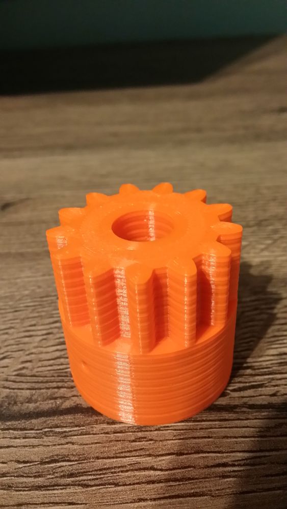
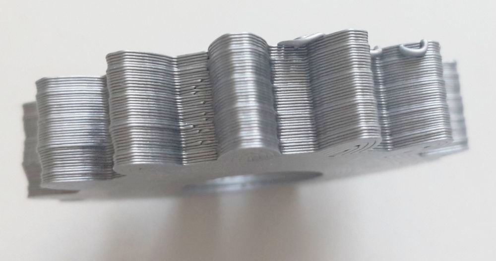
For a long time I cannot handle the problem with sequential layer dimension change every approx 10 layers. As it is visible in attached files.
To me it looks like the temperature is changing in a certain layer sequence but I cannot figure out how to change it manually.
I measure E-steps with new filaments and make amends if needed. So E-steps are ok.
The hot-end's PID was done many times. It was done in accordance to [reprap.org]
I was running M303 E0 S220 C8 and then modified Kp, Ki, Kd, in configutation_h and then loaded the firmware.
Current values are: READ: Kp: 33.49 Ki: 3.05 Kd: 91.90
May I ask for advise?
Maybe there is a way to tune it manually or maybe there is something I do wrong, but what?
If it is Z-wobble? The rod is slightly bended. I see it as it turns. But when the bed (Z axis) is going up or down I see no side movement of the bed at all because the linear bearing is holding it tight in a position.
Edited 3 time(s). Last edit at 04/16/2019 02:54AM by icp.
I am using Felix printers frame with Mendel 90 electronics: Arduino+Ramps 1.4.+Marlin 1.1.9.
I print with PLA.
H-E temp: 220'C.
Bed temp: 60'C.
Speeds: more less standard speeds.
Extruder: E3D-v6 Nozzle: 0.4mm. Primary layer height: 0.2 in this case. Extrusion width (automatic) 0.48mm.
For a long time I cannot handle the problem with sequential layer dimension change every approx 10 layers. As it is visible in attached files.
To me it looks like the temperature is changing in a certain layer sequence but I cannot figure out how to change it manually.
I measure E-steps with new filaments and make amends if needed. So E-steps are ok.
The hot-end's PID was done many times. It was done in accordance to [reprap.org]
I was running M303 E0 S220 C8 and then modified Kp, Ki, Kd, in configutation_h and then loaded the firmware.
Current values are: READ: Kp: 33.49 Ki: 3.05 Kd: 91.90
May I ask for advise?
Maybe there is a way to tune it manually or maybe there is something I do wrong, but what?
If it is Z-wobble? The rod is slightly bended. I see it as it turns. But when the bed (Z axis) is going up or down I see no side movement of the bed at all because the linear bearing is holding it tight in a position.
Edited 3 time(s). Last edit at 04/16/2019 02:54AM by icp.
|
Re: Sequential layer dimension change April 16, 2019 03:44AM |
Registered: 9 years ago Posts: 752 |
Yes that's z wobble, try putting a ruler next to your printed part, is the spacing 2mm (or the pitch of the lead screw)?
The dimension doesn't change, it's just shifted from one layer to the next. It's cyclic every rotation of the lead screw.
Even a microscopic amount will show up in your prints. If you look at a corner you may not even see the wobble on the edge but the way light catches on the layers will highlight it.
Leadscrews should be straight, I'd replace them.
Edit: Ah yes, 0.2 layer height x10 layer = 2mm.
Edited 3 time(s). Last edit at 04/16/2019 03:51AM by imqqmi.
--
Kind regards
Imqqmi
NFAN CoreXY printer:
[reprap.org]
|
Re: Sequential layer dimension change April 16, 2019 04:04AM |
Registered: 5 years ago Posts: 7 |
That's right. The pitch is 2mm and printed objects have a step change every approx 2mm of height. Even elements printed with 0.15 and 0.10 mm also around 2mm. It all ads up to your conclusion.
I will replace the long nut or maybe the rod as well.
I will search for sets of threaded rods with nuts meant for reprap. More expensive but if that will do the job then ok.
Thank you imqqmi. I appreciate it.
I will replace the long nut or maybe the rod as well.
I will search for sets of threaded rods with nuts meant for reprap. More expensive but if that will do the job then ok.
Thank you imqqmi. I appreciate it.
|
Re: Sequential layer dimension change April 16, 2019 06:49AM |
Registered: 11 years ago Posts: 5,780 |
Z wobble offsets the layers so that on one side of the print any given layer will bulge and on the opposite side it will create a concavity, like very small layer shift. That looks more like the layers are not consistent thickness.
Id the bed heated and is it using bang-bang control?
Ultra MegaMax Dominator 3D printer: [drmrehorst.blogspot.com]
Id the bed heated and is it using bang-bang control?
Ultra MegaMax Dominator 3D printer: [drmrehorst.blogspot.com]
|
Re: Sequential layer dimension change April 16, 2019 07:52AM |
Registered: 8 years ago Posts: 413 |
What is the connection between the lead screw and the motor?
looks a bit like something is winding up then suddenly releasing. If the bed is not free to slide in Z and the connector is of the flexible type it might be winding up the connector until the load is high enough to release.
If you have the flexible spiral type connector I suggest making sure the motor is pulling the connector around with increasing Z.
|
Re: Sequential layer dimension change April 16, 2019 08:45AM |
Registered: 5 years ago Posts: 7 |
Quote
the_digital_dentist
Z wobble offsets the layers so that on one side of the print any given layer will bulge and on the opposite side it will create a concavity, like very small layer shift. That looks more like the layers are not consistent thickness.
Id the bed heated and is it using bang-bang control?
The bed is heated during the print to 60'C and the nozzle is 220'C.
Yes it makes sense. If there is a play it goes all in one direction, not all directions.
Bang-bang control- I do not know how to do that. I have to find out.
Quote
MCcarman
What is the connection between the lead screw and the motor?
looks a bit like something is winding up then suddenly releasing. If the bed is not free to slide in Z and the connector is of the flexible type it might be winding up the connector until the load is high enough to release.
If you have the flexible spiral type connector I suggest making sure the motor is pulling the connector around with increasing Z.
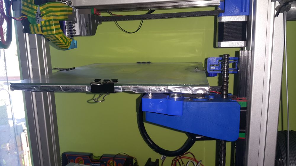
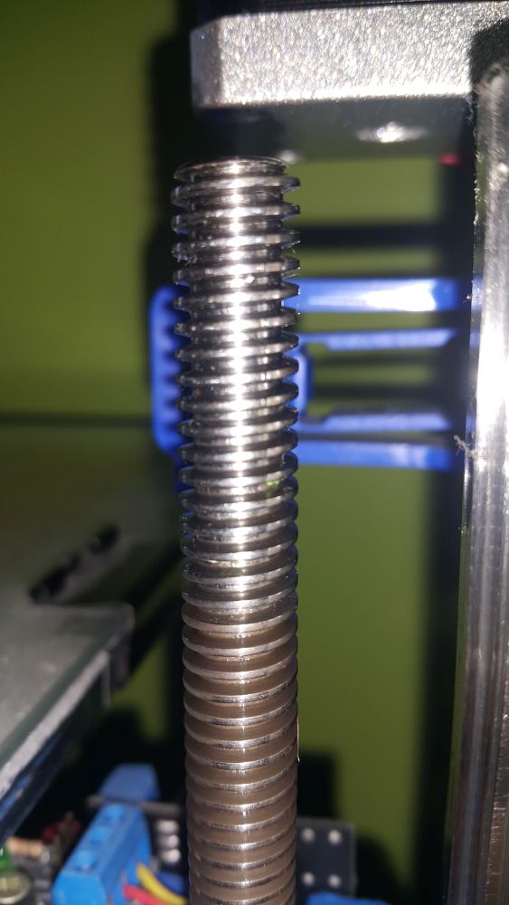
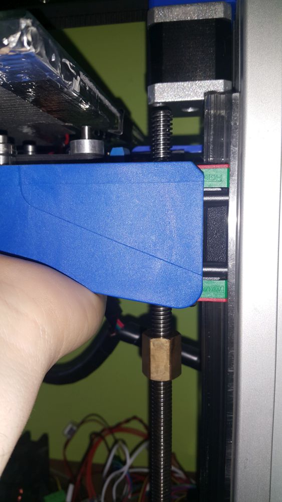
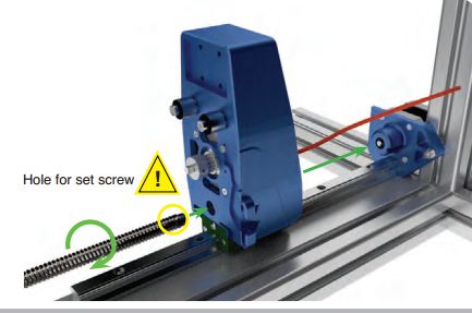
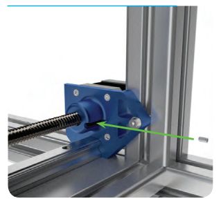
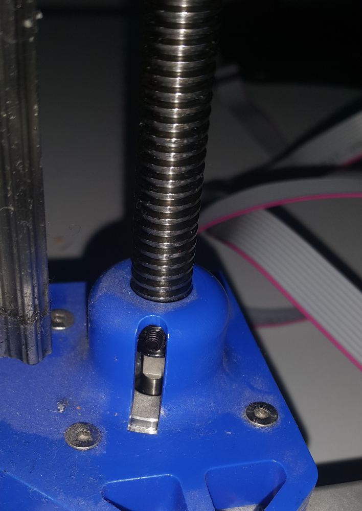
This long nut is sunk inside the blue big part [Bed mount-1.jpg] in 1st post above. There is a hexagonal shape inside. The trapeze threaded rod is connected to motor directly with the set screw as shown in attachment [Rod- set screw-3.jpg]. The motor's shaft has machined flat surface and the set screw is tightened to this flat surface. I have checked this set screw. It is fastened properly. I think that's ok over here.
The rod itself has a little play inside the nut and I understand it has to be like that to more freely. The Hiwin linear bearing makes the horizontal movement of the blue big bracket impossible. Any horizontal movement is completely disabled. While I am trying to move it by hand there is no play at all.
Yes it looks like something is either causing the tension and after the maximum is reached it is being released. The height of the layers change (approx 2mm) points to pitch of the thread which is also 2mm.
Or maybe the temperature is going crazy but would it always appear at the height of approx 2mm regardless of the primary layer height?
|
Re: Sequential layer dimension change April 16, 2019 09:24AM |
Registered: 9 years ago Posts: 752 |
I agree with digital dentist, seems to be an up/down motion inconsistency. The thing is to rule out what's causing it.
Do you have a dial indicator? You could try heating the bed with the dial indicator mounted on something not on the 3D printer and see if it moves up or down. Bang/bang can cause some beds to warp. It would have to be in sync with layer times somehow, I would think the chance of that to be quite slim.
You can also check if the amount you move the bed corresponds with the amount measured and if this is a linear or more cyclic motion. There's always some play or compliance.
You could measure side to side motion on the side of the blue brackets (flat surface) or clamp something square on the bed to see if it wobbles. It may be a combination of factors. Also check if the rods are concentric with the motor shaft, sometimes the hole with the stepper motor connector is too large, and with a set screw can get off center and wobble without the rod being bent, and may also cause binding.
Even if by touch it seems solid, with a dial indicator you often find there's a lot more compliance than you think. When I did the same with 2040 extrusions I was amazed that a light tough could give 10um compliance very easily.
Also check for inconsistencies in the stepper motor motion, lower the bed very slowly and see if you can detect any lateral movement and how consistent it is (linear or in sudden bumps and jumps). Check if the layer heights are also consistent with full steps of the stepper motor (microsteps per mm or steps per mm) rounding errors or microstepping at weaker points may have some influence.
--
Kind regards
Imqqmi
NFAN CoreXY printer:
[reprap.org]
|
Re: Sequential layer dimension change April 16, 2019 09:51AM |
Registered: 5 years ago Posts: 7 |
I might have the dial indicator somewhere in the basement. I have to dive in and search.
It sounds possible. Aluminium expands under temperature. Steel spring washers which hold the bed in level are made out of very thin plate. If they heat up they may loose their inner tension as well and the hole bed will lover for a moment. It sounds possible.
I will check the movement steps again to be 100% sure.
I think I will print the same part with cold table hoping that it will stick well during the print. I will clean the table and use some adhesive spray like Dimafix for PLA.
I have already checked for any derivatives while lifting or lowering the bed from the top to the bottom and back. Visually there is nothing clicking, squeaking or worrying, just smooth move of the blue bracket. The rod is not perfectly balanced but it looks like it does not affect's the bed. But I will search for a new trapeze rod to be sure.
I may try to raise and lower it with slow speed as well. But first I will try to print it with the cold table.
|
Re: Sequential layer dimension change April 16, 2019 11:00AM |
Registered: 5 years ago Posts: 7 |
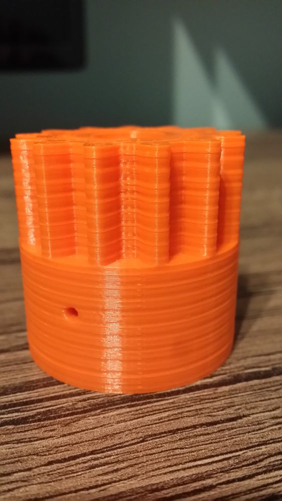
Heat bed: 0'C
Hot end: 220'C
The same part printed and also PLA.
During printing with cold table the print partly detached from the table but the problem was already visible so I stopped it. It's the left side of the print so let's not get into it.
Overall it looks like exactly each 9th and 10th layer there is a change.
So it looks like we may exclude the bed temperature deviations from the main causes list.
During the printing I was looking at hot end's temperature deviations. They were varying on average between approx: 219.79'C and 220.25'C. So it looks ok. In attachment I put the notepad file with last communication logs during the printing. Maybe here we may find something?
I will look for rods and nuts tomorrow.
|
Re: Sequential layer dimension change April 17, 2019 04:59AM |
Admin Registered: 13 years ago Posts: 6,998 |
|
Re: Sequential layer dimension change April 17, 2019 07:53AM |
Registered: 5 years ago Posts: 7 |
|
Re: Sequential layer dimension change April 17, 2019 01:14PM |
Registered: 5 years ago Posts: 7 |
Results:
It's difficult to measure correctly when it's not 100% of Z steps but it looks like this distance is approx 2mm in every case.
- by 100% of Z steps- the change is exactly every 10 layers so by 0.2mm it gives 2mm z wobble as imqqmi wrote,
- by 80% also approx 2mm,
- by 130% also approx 2mm.
First I will dismantle the rod and have a close look at it's connection with the motor.

It's difficult to measure correctly when it's not 100% of Z steps but it looks like this distance is approx 2mm in every case.
- by 100% of Z steps- the change is exactly every 10 layers so by 0.2mm it gives 2mm z wobble as imqqmi wrote,

- by 80% also approx 2mm,

- by 130% also approx 2mm.
First I will dismantle the rod and have a close look at it's connection with the motor.
Sorry, only registered users may post in this forum.