Help, internal size of part(s) too small...
Posted by Qsilver
|
Help, internal size of part(s) too small... November 29, 2013 02:10PM |
Registered: 11 years ago Posts: 40 |
I hope someone here can help me.
I have attached a couple of images to explain.
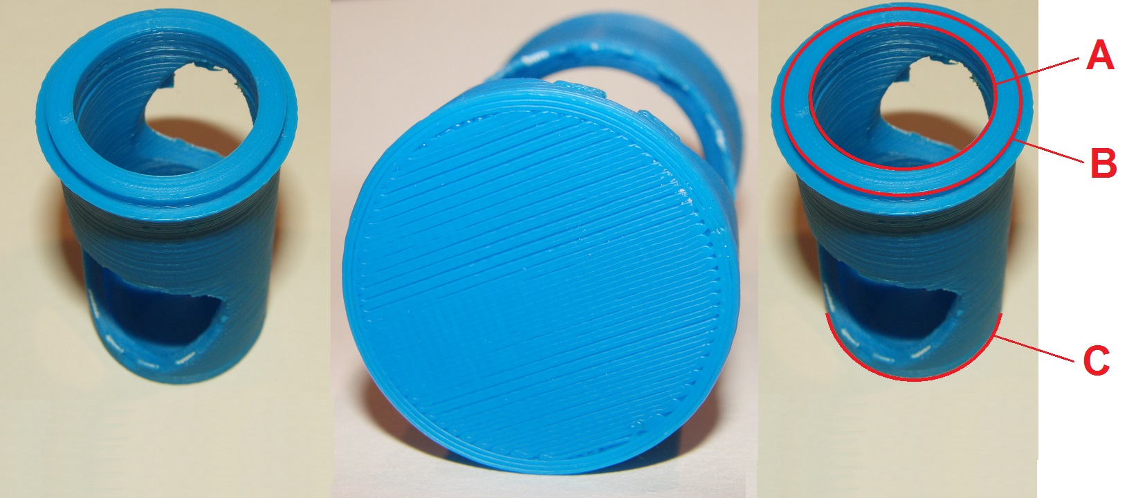
My inside dimensions (like A in picture) are printing too small.
Outside dimensions (B & C) are all printing good.
What could be causing this?
Part designed in SolidWorks exported as STL...
Richard
I have attached a couple of images to explain.
My inside dimensions (like A in picture) are printing too small.
Outside dimensions (B & C) are all printing good.
What could be causing this?
Part designed in SolidWorks exported as STL...
Richard
|
Re: Help, internal size of part(s) too small... November 29, 2013 08:16PM |
Registered: 11 years ago Posts: 1,171 |
|
Re: Help, internal size of part(s) too small... November 30, 2013 01:34AM |
Registered: 11 years ago Posts: 40 |
|
Re: Help, internal size of part(s) too small... November 30, 2013 02:37PM |
Registered: 11 years ago Posts: 40 |
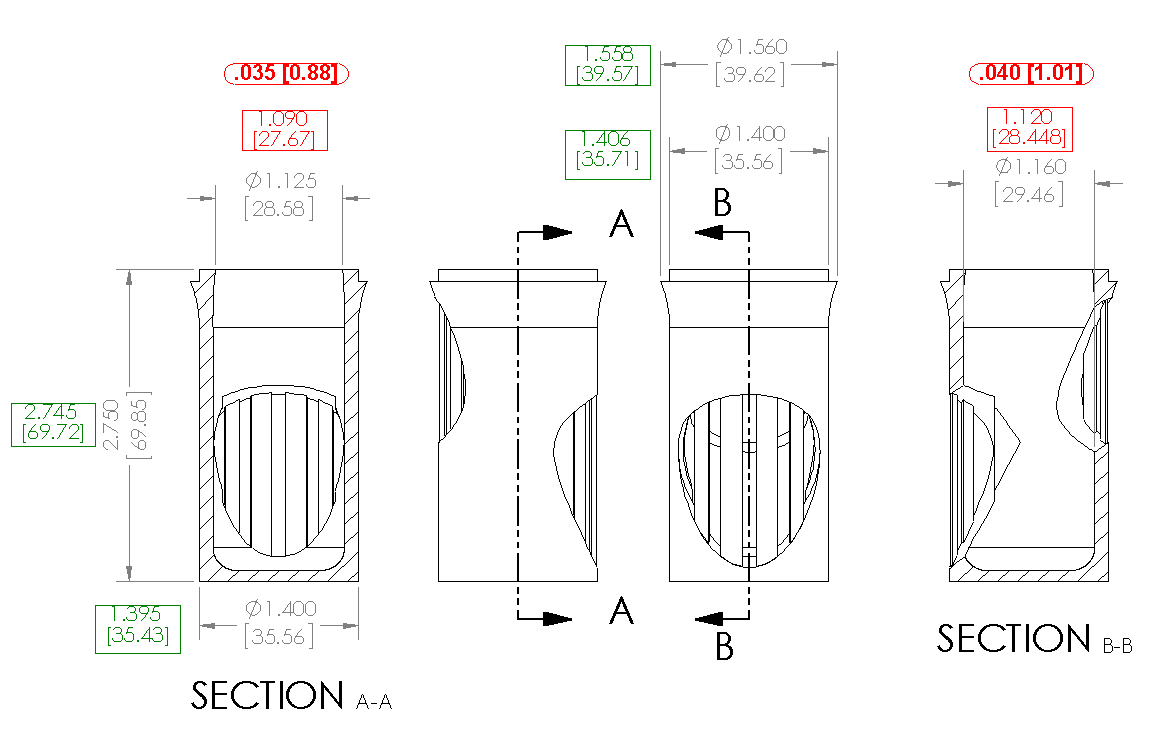
Ok, so I made test part.
A drawing of the test part, and what I measured (Red - average), is attached.
Also the STL file is attached so you can print and see if you get similar results.
My set up is 0.40 nozzle, 0.25 layer height, ABS @ 230, bed at 110. Speeds default.
I measured with digital calipers.
The ID dimensions still are small.
Small holes @ 0.5mm and other locations 0.5 to 0.7
I thought the printer positional accuracy was about 0.013 mm, X-Y
I really like Slic3r but why are these wrong?
Is it just my setup, or is there some reason the software seems to produce incorrect data?
Thanks for your time and responses.
I have noticed a very slight variation in my X dims .vs. Y dims.
about 0. 10 mm. This could be mechanical. I drive both axis with aluminum timing pulley T2.5-16, so I will double check my steps in firmware.
Richard
A drawing of the test part, and what I measured (Red - average), is attached.

Also the STL file is attached so you can print and see if you get similar results.
My set up is 0.40 nozzle, 0.25 layer height, ABS @ 230, bed at 110. Speeds default.
I measured with digital calipers.
The ID dimensions still are small.
Small holes @ 0.5mm and other locations 0.5 to 0.7
I thought the printer positional accuracy was about 0.013 mm, X-Y
I really like Slic3r but why are these wrong?
Is it just my setup, or is there some reason the software seems to produce incorrect data?
Thanks for your time and responses.
I have noticed a very slight variation in my X dims .vs. Y dims.
about 0. 10 mm. This could be mechanical. I drive both axis with aluminum timing pulley T2.5-16, so I will double check my steps in firmware.
Richard
|
Re: Help, internal size of part(s) too small... November 30, 2013 03:45PM |
Registered: 13 years ago Posts: 2,947 |
I personally believe the math Slic3r uses to calculate the extrusion width is completely wrong and causes this. I should say that I no longer use Slic3r because of all the bugs so things may have changed. Also all slicers seem to print holes to small when their extrusion widths are set to the same kind of values Slic3r seems to calculate and especially with the default layer height. If you would like to try manually setting the extrusion widths and set the layer height to no greater than 0.2mm the holes should come out much closer. You can use the calculator in my signature to calculate the correct settings. Be sure to use the intermediate or higher calculator and enter at least both your steps per mm's, nozzle and filament sizes.
| FFF Settings Calculator | Gcode post processors | Geometric Object Deposition Tool Blog |
| Tantillus.org | Mini Printable Lathe | How NOT to install a Pololu driver |
|
Re: Help, internal size of part(s) too small... November 30, 2013 05:24PM |
Registered: 11 years ago Posts: 296 |
well, I think you have by far too big ambitions about accuracy with 3d printers. Think about again.
You have a nozzle that can make a line that is 0,40 wide or larger, never smaller. in layer height direction you can select a layer height smaller than nozzle width and by that get better resolution, but in x,y plane, accuracy is never better than extrusion width or at least half of it. Typical extrusion width is 1.5 to 3 times layerheight, but no linear scale is available for this mostly experience is valid here.
Your holes are in x,y plane and position can be placed very accurate if properly calibrated but that does not help on accuracy of dimensions due to a relative thick extrusion width to be used.
I am not familiar wíth the specific algorithm for making holes in slic3r and of course you can more or less take in consideration of extrusion width as such, but when we as users violate all of these considerations by demanding excessive speeds and different materials and extrusion compensations etc. I doubt that any algorithm would ever be the winner.
You can always try with the specific print to choose small changes of extrusion width and layerheights to find the optimum result for that print, but never expect that there is a standard formula that covers any print with these relative bad nozzle conditions given for accuracy in expectations of 1/10 mm accuracy or whatever very small. Just my point....
Edited 2 time(s). Last edit at 11/30/2013 05:27PM by justcurious.
|
Re: Help, internal size of part(s) too small... November 30, 2013 05:50PM |
Registered: 13 years ago Posts: 2,947 |
Quote
justcurious
well, I think you have by far too big ambitions about accuracy with 3d printers.
I must say this is one of the problems in RepRap. It is believed they can not be that accurate so people except less than they should. I was guilty of this at the beginning too and it was only after seeing some prints in person that were better then my repstrap was doing that I started trying to get perfect prints. Now my prints are always within 0.05mm of the target size and I now model all holes exactly the size I want them. Here is a video of Nopheads test part from his Mendel 90 repo [youtu.be] I printed on Tantillus and the nuts fit perfectly. Here is another video of a person printing m4 thumb screw nuts on his Tantillus [youtu.be] and the nuts fit perfectly and he says he did not model the hole larger at all.
Edited 2 time(s). Last edit at 11/30/2013 05:51PM by Sublime.
| FFF Settings Calculator | Gcode post processors | Geometric Object Deposition Tool Blog |
| Tantillus.org | Mini Printable Lathe | How NOT to install a Pololu driver |
|
Re: Help, internal size of part(s) too small... November 30, 2013 05:56PM |
Registered: 11 years ago Posts: 1,171 |
|
Re: Help, internal size of part(s) too small... November 30, 2013 06:02PM |
Registered: 11 years ago Posts: 296 |
Sublime, you claim that it certainly is possible to get accurate results, but you do not give any directions for this to happen? it is not a good proof that a specific print can be made accurate, that was what I indicated above.
What is the magic to be used to get 0.05 accuracy with every print then?
I did not say that accuracy was impossible but getting to that is some hard work and intuition and for some, selection of best fit tools, but in my opinion there is no easy way getting there.
What is the magic to be used to get 0.05 accuracy with every print then?
I did not say that accuracy was impossible but getting to that is some hard work and intuition and for some, selection of best fit tools, but in my opinion there is no easy way getting there.
|
Re: Help, internal size of part(s) too small... November 30, 2013 06:03PM |
Registered: 13 years ago Posts: 2,947 |
Quote
tmorris9
So Sublime, what program do you use now?
I was thinking of switching to Kisslicer but I am just so familiar with Slic3r that I have not yet.
I use Kisslicer.
| FFF Settings Calculator | Gcode post processors | Geometric Object Deposition Tool Blog |
| Tantillus.org | Mini Printable Lathe | How NOT to install a Pololu driver |
|
Re: Help, internal size of part(s) too small... November 30, 2013 06:07PM |
Registered: 13 years ago Posts: 2,947 |
Quote
justcurious
Sublime, you claim that it certainly is possible to get accurate results, but you do not give any directions for this to happen? it is not a good proof that a specific print can be made accurate, that was what I indicated above.
What is the magic to be used to get 0.05 accuracy with every print then?
I did not say that accuracy was impossible but getting to that is some hard work and intuition and for some, selection of best fit tools, but in my opinion there is no easy way getting there.
I did give instructions in the post above your last one. I explained my beliefs on what causes this and explained to use layer heights less than 0.2 and to set the extrusion widths to the ones from my calculator. If you want more info on how the calculator works you can see [kisslicer.com] and [forums.reprap.org] for more info it would be best to start a new subject in the appropriate forum
| FFF Settings Calculator | Gcode post processors | Geometric Object Deposition Tool Blog |
| Tantillus.org | Mini Printable Lathe | How NOT to install a Pololu driver |
|
Re: Help, internal size of part(s) too small... December 01, 2013 12:39AM |
Registered: 11 years ago Posts: 1,171 |
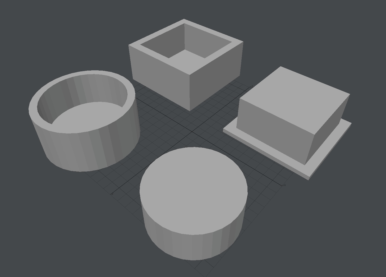
I just did a quick test in Kisslicer. Made the parts (shown in attached image) that are 2mm size. I made a corresponding insert piece to match each and made the insert pieces 100um smaller on each side (to allow a small gap for fitting together) so 200um total. Once printed they did not easily fit together and I thought they would not but found that I could squeeze them together with a pair of pliers (they will never come apart again). Once the parts began to mate up it took what I would call medium-mild pressure to press together (less force than it takes to crack a walnut with pliers). I feel that if the gap was doubled they would slide together by hand easily.
So that's still not perfect sizing but it's pretty close. I feel like it's just the squeezed ribbing on the parts that's preventing it from being perfect.
My setup:
Airwolf 3D printer (Based on Prusa Air)
Budaschnozzle 2.0 with .35mm nozzle
ABS plastic.
Repetier firmware.
Gen 6 board.
So that's still not perfect sizing but it's pretty close. I feel like it's just the squeezed ribbing on the parts that's preventing it from being perfect.
My setup:
Airwolf 3D printer (Based on Prusa Air)
Budaschnozzle 2.0 with .35mm nozzle
ABS plastic.
Repetier firmware.
Gen 6 board.
|
Re: Help, internal size of part(s) too small... December 01, 2013 01:16AM |
Registered: 11 years ago Posts: 1,592 |
I think the problem is with circles, not hex nut holes. Any part I print which requires hexagonal sockets always come out perfect - the nuts will drop in with total precision. Nophead has some info on this somewhere but basically it seems that the more "edges" in a circle, the tighter it will be. A 6 sided nut hole is easy for the extruder just as a square hole would be - it will move in "easier" straight lines so to speak but dragging the filament around a circle seems to cause it to pull towards the center, hence making it smaller.
_______________________________________
Waitaki 3D Printer
_______________________________________
Waitaki 3D Printer
|
Re: Help, internal size of part(s) too small... December 01, 2013 01:27AM |
Registered: 11 years ago Posts: 40 |
Quote
justcurious
well, I think you have by far too big ambitions about accuracy with 3d printers. Think about again.
You have a nozzle that can make a line that is 0,40 wide or larger, never smaller. .....
...
You can always try with the specific print to choose small changes of extrusion width and layerheights to find the optimum result for that print, but never expect that there is a standard formula that covers any print with these relative bad nozzle conditions given for accuracy in expectations of 1/10 mm accuracy or whatever very small. Just my point....
I guess that I would choose to disagree with you on my expectations, to some extent.
I fully believe that a properly calibrated printer should be able to hold +/- 0.1 mm or +/- 0.005 inch. That said, we are extruding a nearly molten plastic.
I'd be happy if it could hold 0.2mm right now on the id's
Look at the print, with measured numbers in red I attached.
The outside diameters are within .25mm on the larger and .15mm on the smaller.
I am very happy with that... max of 0.010 inch.
Look at the insides. 0.60mm, 4 times the error.
That is an error thicker then the extrusion nozzle.
I don't think that is unreasonable to want better.
Rich
|
Re: Help, internal size of part(s) too small... December 01, 2013 01:31AM |
Registered: 11 years ago Posts: 40 |
Quote
waitaki
I think the problem is with circles, not hex nut holes. .......
A 6 sided nut hole is easy for the extruder just as a square hole would be - it will move in "easier" straight lines so to speak but dragging the filament around a circle seems to cause it to pull towards the center, hence making it smaller.
If that is the case then why would large diameters be worse then small ones in error?

Rich
|
Re: Help, internal size of part(s) too small... December 01, 2013 01:51AM |
Registered: 11 years ago Posts: 40 |
|
Re: Help, internal size of part(s) too small... December 01, 2013 01:58AM |
Registered: 13 years ago Posts: 2,947 |
Quote
waitaki
I think the problem is with circles, not hex nut holes. Any part I print which requires hexagonal sockets always come out perfect - the nuts will drop in with total precision. Nophead has some info on this somewhere but basically it seems that the more "edges" in a circle, the tighter it will be.
I personally don't find this is the case when printing at 0.2mm or below and with the width set as per my calculator. I use 64 or 96 sides to almost all of my holes above 12mm and 32 usually for smaller holes
Also don't put to much into the polyholes test by Nophead since he only gets those results with skeinforge and I believe he sets the perimeter extrusion smaller or less flow or something like that to do it. His tests of other slicers all resulted in under size holes regardless of the poly count.
Quote
waitaki
A 6 sided nut hole is easy for the extruder just as a square hole would be - it will move in "easier" straight lines so to speak but dragging the filament around a circle seems to cause it to pull towards the center, hence making it smaller.
See this is why I believe when you print at lower layer heights the holes turn out better. When the layer is higher than 0.2mm the amount of molten plastic in the extrusion allows it to stay soft and get dragged inwards as you put. But with lower layers (and cooling fans for PLA) the plastic stays in place and hardens so it does not get dragged inwards.
| FFF Settings Calculator | Gcode post processors | Geometric Object Deposition Tool Blog |
| Tantillus.org | Mini Printable Lathe | How NOT to install a Pololu driver |
|
Re: Help, internal size of part(s) too small... December 01, 2013 01:59AM |
Registered: 13 years ago Posts: 2,947 |
Quote
Qsilver
Quote
Sublime
.......Now my prints are always within 0.05mm of the target size and I now model all holes exactly the size I want them......
Did you try the attached STL file, doesn't take too long to print.
Rich
I will give it a try and let you know.
| FFF Settings Calculator | Gcode post processors | Geometric Object Deposition Tool Blog |
| Tantillus.org | Mini Printable Lathe | How NOT to install a Pololu driver |
|
Re: Help, internal size of part(s) too small... December 01, 2013 03:04AM |
Registered: 13 years ago Posts: 2,947 |
Ok here is my test of your test part.
I only printed the middle 50mm of the part since it was only the inside dimensions that were in question.
I used:
Kisslicer
0.139mm layers
0.52mm width (0.5mm J-head)
40mm/s perim
32.5mm/s solid infill
45mm/s spars infill
PLA
2 perimeters
25% infill (rounded octagonal)
The 5mm holes were hard to measure because they are against the print bed and the bottom gets a little squished. Also with the bottom layer so thin it was easy to force the calipers into the plastic which made an accurate measurement harder. If the hole were deeper it would be a lot easier to get an accurate measurement.
I only printed the middle 50mm of the part since it was only the inside dimensions that were in question.
I used:
Kisslicer
0.139mm layers
0.52mm width (0.5mm J-head)
40mm/s perim
32.5mm/s solid infill
45mm/s spars infill
PLA
2 perimeters
25% infill (rounded octagonal)


The 5mm holes were hard to measure because they are against the print bed and the bottom gets a little squished. Also with the bottom layer so thin it was easy to force the calipers into the plastic which made an accurate measurement harder. If the hole were deeper it would be a lot easier to get an accurate measurement.
| FFF Settings Calculator | Gcode post processors | Geometric Object Deposition Tool Blog |
| Tantillus.org | Mini Printable Lathe | How NOT to install a Pololu driver |
|
Re: Help, internal size of part(s) too small... December 01, 2013 08:59AM |
Registered: 11 years ago Posts: 40 |
|
Re: Help, internal size of part(s) too small... December 17, 2013 04:12AM |
Registered: 11 years ago Posts: 369 |
Sublime, I've tried using your calculator before but it has baffled me. I've taken another look just now and maybe I've learned a lot more since, but the words are starting to have a bit more meaning. 
I still am not sure however whether using the figures that it spits out will actually help me;
I have a Mendel90, I print ABS at 0.2mm layer height, 0.4mm nozzle and 0.5mm extrusion width.
My current workflow involves plating up using Repetier and slicing with Slic3r (I have multiple profiles setup already for various filaments) to generate gcode files, which I either upload to Octoprint or copy to the printer via SD.
My external dimensions are usually fine (bar a little excess squish on the first layer that sometimes needs filing/paring off) but internal dimensions, whether they're circular holes or just square cut-outs are often out by half the extrusion width. This means that I have to add 0.5mm to all internal dimensions in order to get them to fit (ok it varies depending on the size of the hole)!
When I plug my figures into the calculator it suggests that extrusion width should be 0.48mm rather than my current setting of 0.5mm - if I make this change in Slic3r then will I really see a dramatic improvement, or do I need to accept that Slic3r will never produce accurate objects such as those you have shown above? Have I even used the calculator correctly?
|
Re: Help, internal size of part(s) too small... December 17, 2013 05:51AM |
Registered: 11 years ago Posts: 1,171 |
|
Re: Help, internal size of part(s) too small... December 17, 2013 06:23AM |
Registered: 11 years ago Posts: 369 |
Oh I see. I thought I read in a post above that as long as the layer height is below 0.2mm and the extrusion width is set according to the calculator then holes come out better.
I've been trying to avoid moving to a new slicing tool only because I'm pretty proficient with my current workflow, but it is looking more and more inevitable. Next question then is whether Kisslicer goes far enough to produce accurate dimensions, or should I jump straight to Skeinforge?
I've been trying to avoid moving to a new slicing tool only because I'm pretty proficient with my current workflow, but it is looking more and more inevitable. Next question then is whether Kisslicer goes far enough to produce accurate dimensions, or should I jump straight to Skeinforge?
|
Re: Help, internal size of part(s) too small... December 17, 2013 08:38AM |
Registered: 11 years ago Posts: 296 |
|
Re: Help, internal size of part(s) too small... December 17, 2013 12:49PM |
Registered: 13 years ago Posts: 2,947 |
Quote
tmorris9
I might be mistaken but I believe the calculator is for use with Kisslicer. And the tool path is off in slic3r so no settings will ever make holes the right size.
Yeah there is currently no proof of this. If you make a large cube with a single hole in it a known dimension and then slice it. You can then open it in a text editor and look at the coordinates. You will either find it is the hole size plus the extrusion width in which case it does not make a mistake, or you will confirm what you have said and need to show the developers of Slic3r because they have never found such proof.
| FFF Settings Calculator | Gcode post processors | Geometric Object Deposition Tool Blog |
| Tantillus.org | Mini Printable Lathe | How NOT to install a Pololu driver |
|
Re: Help, internal size of part(s) too small... December 17, 2013 12:55PM |
Registered: 13 years ago Posts: 2,947 |
Quote
QuackingPlums
Sublime, I've tried using your calculator before but it has baffled me. I've taken another look just now and maybe I've learned a lot more since, but the words are starting to have a bit more meaning.
I still am not sure however whether using the figures that it spits out will actually help me;
I have a Mendel90, I print ABS at 0.2mm layer height, 0.4mm nozzle and 0.5mm extrusion width.
My current workflow involves plating up using Repetier and slicing with Slic3r (I have multiple profiles setup already for various filaments) to generate gcode files, which I either upload to Octoprint or copy to the printer via SD.
My external dimensions are usually fine (bar a little excess squish on the first layer that sometimes needs filing/paring off) but internal dimensions, whether they're circular holes or just square cut-outs are often out by half the extrusion width. This means that I have to add 0.5mm to all internal dimensions in order to get them to fit (ok it varies depending on the size of the hole)!
When I plug my figures into the calculator it suggests that extrusion width should be 0.48mm rather than my current setting of 0.5mm - if I make this change in Slic3r then will I really see a dramatic improvement, or do I need to accept that Slic3r will never produce accurate objects such as those you have shown above? Have I even used the calculator correctly?
Since you are already manually setting the extrusion width to 0.5 I doubt the 0.02 will make much of a difference. This was more about the auto defaults being completely out to lunch. I read someone that made a chart of Slic3r's auto extrusion widths and they showed it would try and make the extrusions 1.6mm wide with a 0.5mm nozzle at a height of something like 0.1mm which is completely wrong and would cause major issues. Also are you using speeds similar to what my calculator says? If you are running a lot faster then it could be causing to much back pressure which when it slows for the small holes causes over extrusion. Also are the temperatures similar to the ones calculated? The calculator can not get them correct but are a good guide line as to where to start. If the temp is too high the plastic may be to liquid which again results in over extrusion when it slows down.
| FFF Settings Calculator | Gcode post processors | Geometric Object Deposition Tool Blog |
| Tantillus.org | Mini Printable Lathe | How NOT to install a Pololu driver |
|
Re: Help, internal size of part(s) too small... December 17, 2013 03:03PM |
Registered: 11 years ago Posts: 40 |
Quote
justcurious
Quote
tmorris9
And the tool path is off in slic3r so no settings will ever make holes the right size.
Is it possible that you can give us some documentation on this statement, which i believe untill otherwise proofed is your own experience.
Hi,
I am not trying to start any debates as to which slicer may or may not have problems..
If there is a software problem with Slic3r, I would like to help it get resolved. As I said I like the program.
Since I made the test part, and the stl, I should be able to look at the g-code created and determine where I see errors.
Let me say percieved errors.
Richard
|
Re: Help, internal size of part(s) too small... December 18, 2013 05:26AM |
Registered: 11 years ago Posts: 369 |
Quote
Sublime
Since you are already manually setting the extrusion width to 0.5 I doubt the 0.02 will make much of a difference. This was more about the auto defaults being completely out to lunch. I read someone that made a chart of Slic3r's auto extrusion widths and they showed it would try and make the extrusions 1.6mm wide with a 0.5mm nozzle at a height of something like 0.1mm which is completely wrong and would cause major issues. Also are you using speeds similar to what my calculator says? If you are running a lot faster then it could be causing to much back pressure which when it slows for the small holes causes over extrusion. Also are the temperatures similar to the ones calculated? The calculator can not get them correct but are a good guide line as to where to start. If the temp is too high the plastic may be to liquid which again results in over extrusion when it slows down.
My extrusion width of 0.5mm is based on a W/H ratio of 2.5 (gleaned from one of nophead's threads here as ideal for ABS) - I have created a lookup table that gives me the extrusion width values for all valid combinations of W/H and H that I am likely to use, and set this value manually for each filament. I have to admit I don't understand how to measure the other influences such as die swell and optimal speed. I have set all my print speeds to 40mm/s (again I think this is a nophead recommendation), which is lower than the 55mm/s suggested by your Basic calculator.
I notice that if I use the Basic calculator with these values then I get a message that says "The current layer height of 0.2mm has a rounding error of 000nm per layer." but if I use the Intermediate calculator then it says my rounding error is 029nm. The additional figures I have plugged into the Intermediate calculator are the target speed (= 40mm/s as currently set) and the E steps per mm (straight from my Marlin firmware = 516.86mm). Z-steps per mm has been left as default and I'm a bit confused why there's nowhere to input my extrusion width.
I also don't understand how the recommended print temperatures work. So far I have been "calibrating" my temps based on cranking it up until it starts oozing, then backing off a bit. This results in an extrusion temperature of 235C which is giving good adhesion on a PET-covered heated bed at 115C (surface temperature) first layer, 105C subsequent layers. The recommended temperatures from the calculator are a bit lower?
Apologies for hijacking this thread - I am keen to learn more in this area and am happy to take the discussion elsewhere if necessary!
|
Re: Help, internal size of part(s) too small... December 18, 2013 11:26AM |
Registered: 13 years ago Posts: 2,947 |
Quote
QuackingPlums
Quote
Sublime
Since you are already manually setting the extrusion width to 0.5 I doubt the 0.02 will make much of a difference. This was more about the auto defaults being completely out to lunch. I read someone that made a chart of Slic3r's auto extrusion widths and they showed it would try and make the extrusions 1.6mm wide with a 0.5mm nozzle at a height of something like 0.1mm which is completely wrong and would cause major issues. Also are you using speeds similar to what my calculator says? If you are running a lot faster then it could be causing to much back pressure which when it slows for the small holes causes over extrusion. Also are the temperatures similar to the ones calculated? The calculator can not get them correct but are a good guide line as to where to start. If the temp is too high the plastic may be to liquid which again results in over extrusion when it slows down.
My extrusion width of 0.5mm is based on a W/H ratio of 2.5 (gleaned from one of nophead's threads here as ideal for ABS) - I have created a lookup table that gives me the extrusion width values for all valid combinations of W/H and H that I am likely to use, and set this value manually for each filament. I have to admit I don't understand how to measure the other influences such as die swell and optimal speed. I have set all my print speeds to 40mm/s (again I think this is a nophead recommendation), which is lower than the 55mm/s suggested by your Basic calculator.
2.5 works fine for layer heights like you are using but that math all falls apart when you try and go lower. 2.5 times 0.1mm is only 0.25mm and from a 0.5mm nozzle you will have nothing but failures.
All the fields have mouse over messages to help.
Die swell is the difference between the nozzle diameter and the size of the filament when extruded into the air (purging).
The optimal speed is most likely the speed that nophead uses in his default profile. But the default value in the calculator is usually good enough unless you want to print a lot slower or a lot faster. It mainly uses volume per second calculations to determine the correct speed. The optimal speed is there to try and maintain speed when the layer is so small that to maintain the volumetric speed the axis would have to travel at like 1000mm/s which is not realistic.
Quote
QuackingPlums
I notice that if I use the Basic calculator with these values then I get a message that says "The current layer height of 0.2mm has a rounding error of 000nm per layer." but if I use the Intermediate calculator then it says my rounding error is 029nm. The additional figures I have plugged into the Intermediate calculator are the target speed (= 40mm/s as currently set) and the E steps per mm (straight from my Marlin firmware = 516.86mm). Z-steps per mm has been left as default and I'm a bit confused why there's nowhere to input my extrusion width.
The basic uses all the default values for Tantillus and since the layer optimization is based on the Z steps per mm it will give different results. The layer rounding is not that important since you use metric lead screws and should have no rounding errors on normal layer heights.
The E steps per mm are used in the minimum layer calculations.
Quote
QuackingPlums
I also don't understand how the recommended print temperatures work. So far I have been "calibrating" my temps based on cranking it up until it starts oozing, then backing off a bit. This results in an extrusion temperature of 235C which is giving good adhesion on a PET-covered heated bed at 115C (surface temperature) first layer, 105C subsequent layers. The recommended temperatures from the calculator are a bit lower?
The temperatures are calculated by taking the temperatures used at two different flow rates and then finding the temperature used for the calculated flow rate. But since the numbers it uses are based on my filament plus some guessing the only way to know is to do a lot of testing and enter the value in the custom temp fields or the advanced or higher calculator. I often lower the temp until failure and then increase the temp by 10-15 deg to find the correct temp.
Layer height * extrusion width * speed = volume per second
There is also an explanation of how it works [kisslicer.com] and [forums.reprap.org]
Edited 1 time(s). Last edit at 12/19/2013 07:10PM by Sublime.
| FFF Settings Calculator | Gcode post processors | Geometric Object Deposition Tool Blog |
| Tantillus.org | Mini Printable Lathe | How NOT to install a Pololu driver |
|
Re: Help, internal size of part(s) too small... December 18, 2013 08:21PM |
Registered: 11 years ago Posts: 1,171 |
OK, I know just enough about gcode to be dangerous. True my assessment of the tool patch is based on assumption as no setting I have tried (hundreds and all I have seen across several boards) produces the correct size. I admit that it was a logical conclusion rather than fact.
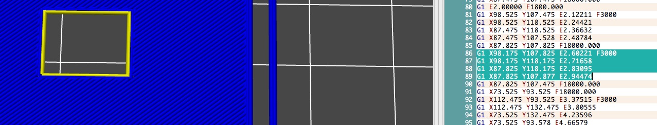
So if you look at the enclosed image, I have highlighted an inner square hole (I wanted to eliminate issues with radius problems for this example) can you tell me based on the highlighted info what the size of the hole is in this object. And if possible explain to me how you calculate the size using the gcode?
Thanks!

Sorry, only registered users may post in this forum.