Help, internal size of part(s) too small...
Posted by Qsilver
|
Re: Help, internal size of part(s) too small... January 03, 2014 10:53AM |
Registered: 13 years ago Posts: 228 |
We could probably do something right now, while we figure out the bigger picture.
It looks like there are two quick possible workarounds for now:
I wonder what the pros and cons are of each method. What do you think?
Option B makes me wonder that while we'd have a way to compensate for dimensional errors, there might be less overlap (and thus a possible gap?) between the outer loop and the one next to it.
Option A seems easier to tune since it's just a straight compensation value.
It looks like there are two quick possible workarounds for now:
- An inset value (in mm) to apply to the outer loop (in addition to extrusion_width/2 which is already applied)
- An additional extrusion multiplier to apply to the outer loop (to allow user to reduce flow as Sublime proposes)
I wonder what the pros and cons are of each method. What do you think?
Option B makes me wonder that while we'd have a way to compensate for dimensional errors, there might be less overlap (and thus a possible gap?) between the outer loop and the one next to it.
Option A seems easier to tune since it's just a straight compensation value.
|
Re: Help, internal size of part(s) too small... January 04, 2014 04:25AM |
Registered: 13 years ago Posts: 486 |
+1 vote for the inset value.
The simple procedure I used for calibration was to first calibrate the flow by printing solid objects based on when the top surface is properly filled and smooth. I realize that the best way to calibrate flow is just to measure the amount of filament that is pulled into the extruder, but that will not take into account the fact that you can't actually fully fill a rectangular path as Qsilver's diagrams so eloquently suggest. The flow error because of not-quite 100% stuffing is a likely to be W/T dependent and perhaps also dependent on the viscosity of the plastic being printed (which will be temperature dependent too), so that is going to be quite difficult to incorporate into a slicing model.
Once the flow is right, print a single walled box and use a micrometer to measure the wall thickness. The thickness will be wider than the rectangular sliced filament width because of the filament path's rounded edges. You then want to compensate for this filament width error by setting an inset that is half of the error. When I did this with skeinforge (and there were a number of settings that I needed to fudge to get the perimeter to slice wider than the rest of the model but also retain the same flow rate) I found that the models I printed became very accurate. Nut traps were the right size, dovetail joints designed with minuscule tolerances fitted nicely. The way I did it in skeinforge though would have probably also spaced the loop inside the perimeter off from the perimeter by the same small correction, so if there is some cumulative error when printing inner loops first, that would also have been less of a problem for me.
So just the simple addition of an inset value should make getting good dimensional accuracy much easier and would also provide a good basis for experimentation that would be needed to do some more analytical development of compensation algorithms.
Edit: I didn't realize that Slic3r used different models based on whether the extrusion width was wider or narrower than the nozzle. That could get quite confusing when trying to work out what is going on. Wouldn't it make more sense to base it on the extruded W/T?
Edited 1 time(s). Last edit at 01/04/2014 04:30AM by Greg Frost.
|
Re: Help, internal size of part(s) too small... January 05, 2014 01:51PM |
Registered: 13 years ago Posts: 228 |
Thank you Greg. Also, nice to read from you after long time.
I'll wait a bit to hear opinions from other people who have partecipated to this thread.
I'm not sure I would recommend a calibration procedure based on the measurement of a single-wall object since the absence of an inner loop would not reproduce the (possible but not very known) outwards shift that the outer loop gets when it's extruded after the inner one. I was thinking about calibrating with a plain cube. Your inset compensation would be equal to (measured_size - expected_size)/2.
To be more exact than my previous message, Slic3r model works this way:
I should make a drawing, but I hope this is clear enough. As you see, the model is continuous. It's the best model I could come of to represent what happens below the nozzle in my imagination...
I'll wait a bit to hear opinions from other people who have partecipated to this thread.
I'm not sure I would recommend a calibration procedure based on the measurement of a single-wall object since the absence of an inner loop would not reproduce the (possible but not very known) outwards shift that the outer loop gets when it's extruded after the inner one. I was thinking about calibrating with a plain cube. Your inset compensation would be equal to (measured_size - expected_size)/2.
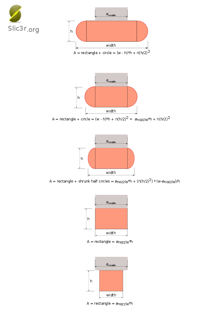
To be more exact than my previous message, Slic3r model works this way:
- when width >= (nozzle_diameter + layer_height), the model is equal to a rectangle with two half circles at the sides (hence layer_height/2 on each side)
- when width < (nozzle_diameter + layer_height), a similar shape is assumed: a rectangle below the nozzle with two shrunk half circles at its sides (each one being (width-nozzle_diameter)/2 wide)
- when width == nozzle_diameter the half circles are completely compressed so there's only a rectangle below the nozzle (w*h)
- the last formula (w*h) is also applied when width < nozzle_diameter, but using such a width is not recommended and never happens automatically
I should make a drawing, but I hope this is clear enough. As you see, the model is continuous. It's the best model I could come of to represent what happens below the nozzle in my imagination...
|
Re: Help, internal size of part(s) too small... January 05, 2014 02:30PM |
Registered: 13 years ago Posts: 228 |
I made a drawing 
The flow logic in Slic3r is implemented in this single C++ file: [github.com]
Edited 1 time(s). Last edit at 01/05/2014 02:31PM by Sound.
The flow logic in Slic3r is implemented in this single C++ file: [github.com]

Edited 1 time(s). Last edit at 01/05/2014 02:31PM by Sound.
|
Re: Help, internal size of part(s) too small... January 05, 2014 03:39PM |
Registered: 13 years ago Posts: 486 |
|
Re: Help, internal size of part(s) too small... January 05, 2014 04:03PM |
Registered: 11 years ago Posts: 296 |
|
Re: Help, internal size of part(s) too small... January 05, 2014 04:15PM |
Admin Registered: 17 years ago Posts: 7,879 |
I think it is always a rectangle with semicircular sides when extruded with nothing on either side. It can't form a rectangle unless it is bounded by rectangles on each, which never happens.
[www.hydraraptor.blogspot.com]
[www.hydraraptor.blogspot.com]
|
Re: Help, internal size of part(s) too small... January 05, 2014 10:03PM |
Registered: 10 years ago Posts: 103 |
Hi all, I've been following this and all the other threads about hole sizes for a short while now. The other day I spent a day printing test pieces to see if I could get my holes to the correct size by disregarding any actual sizes and widths and trying to fudge things, and like everyone else, realised I couldn't.
I think I can probably comment on some of the confusion out there.
I was reading a thread which said the tool path was decided by the nozzle size variable only and the amount of extrusion was decided by the value under the advanced tab in print settings. From the above (and my testing) I presume this is wrong.
If this had been true, using a 0.5 nozzle, I could have set nozzle size to 0.7, extrusion width to 0.4 and logically I think I'd have been close. (or I'd at least have seen my holes increase in size!)
When testing, what I realised I really wanted was a way to adjust the actual amount of extrudiate so that the bead matched the width it should, but independently for that feature.
In case I'm barking up the wrong tree.
Q) The tool path is affected by the width in the advanced tab isn't it?
So I realised what I really wanted to do (to fudge it, but now not sure it is a fudge, it more and more feels like what you want to do) was set the extrusion width to 0.6mm, which would move the tool path a bit, but I wanted to at the same time set an extrusion multiplier so that I could prevent extra extrusion.
I.E. I wanted to set
Perimeter Extrusion Width 120% (to move the tool path a bit)
Perimeter Extrusion Multiplier 80% (to stop it actually extruding 120% of filament)
Of course if I could set an extrusion multiplier, I wouldn't have to oversize the path width would I !
I don't know what the names of these 2 parameters should be for maximum clarity, but I feel if there is an extra input next to each extrusion width on the advanced tab that affects the amount of extrusion, then slicer will be fixed.
To me, they are called
"Slicer Path Width"
"Extrudiate Multiplier"
or some such.
Apologies for this slightly rambling mail, I'm trying to give you an insight of how a relative noob sees it.
"set the width high, brilliant, the tool path has moved over, oh hangon, I also have more extrusion, if only
I could stop that"
The thing is, I just see that as being able to tune the extrusion on a specific part of the model.
I'm thinking of testing this theory by issuing M92 Ennn during a test print to prove adjusting that extrusion will fix it.
I can't get back to my printer for a few days, I think that would be a good proof of concept though.
Btw, isn't measuring your skirt a good way of finding your actual width ? (presuming you're not overly squishing into your bed?)
|
Re: Help, internal size of part(s) too small... January 06, 2014 06:02AM |
Registered: 13 years ago Posts: 228 |
@GregFrost, the relationship between flow rate and resulting shape does not vary whether it's used for perimeters or infill, so the math you see applies to any kind of extrusion (except for bridging). The diagram I showed says nothing about the spacing of two adjacent toolpaths, so I wonder why you think it would lead to gaps. This is the model that links flow rate and expected width. Then there's another couple formulas used to decide how far two lines must be spaced. (Anyway, two adjacent loops are treated exactly like two adjacent solid infill lines.)
@justcurious, I implemented a dynamic width algorithm which is disabled for now because of bad performance. It would be suboptimal with Bowden extruders because of non-constant pressure. But anyway that's a different topic. That's more about "how to fill gaps". Here we're discussing how to predict the actual width according to a given flow rate, which applies to a dynamic logic too. (By the way, dynamic stretching of extrusion width is already automatically applied to solid infill to prevent gaps caused by remainders. It's one of those hidden things that increase processing time in Slic3r but improve quality.)
@nophead, I agree that straight walls are unlikely, but I wasn't able to think of a better math for the 3rd and the 4th case in the picture. Can you help me on that?
|
Re: Help, internal size of part(s) too small... January 06, 2014 08:47AM |
Admin Registered: 17 years ago Posts: 7,879 |
I don't think the maths ever changes for a single outline. It always has a flat bottom and a flat top and the ends are rounded by surface tension. Nothing magic happens when it is the same or narrower than the nozzle aperture, it is simply a volume of plastic constrained top and bottom. However it always wants to come out wider as it likes to flow sideways, so if you actually stretch it so much that it is the same width as the nozzle or smaller it snaps when spanning gaps and cuts corners, etc, and generally doesn't work well. It switches sides of the nozzle as the direction changes, a bit like backlash, which affects the shape of corners.
The way I view it the die swell cross section gives the maximum filament area. The maximum layer height is then the height you get from that area with the minimum W/T (I use 1.5 as lower values don't have good adhesion). I also take 1.5 times the maximum layer height as the maximum width and reduce the width towards the width of the nozzle as the layer height is reduced. This is because as the gap between the nozzle and the layer below gets less the plastic meets more resistance flowing sideways. So as the layer height tends to zero the width should tend towards the nozzle width. Also it is advantageous as you can get better horizontal resolution.
So using the rounded rectangle model for single outlines always gives the correct size. I then use enough plastic to fill the rectangle for the infill and choose the infill outline overlap to account for the rounded inside edge of the outline. The only bug in the model is that infill is actually only constrained on one side until the last line goes in. That means it spreads more one way than the other so is offset from the nozzle. If it is done from two directions (which will always happen if there is a hole) I get a ridge where the last line tries to fit into a reduced gap. I am not sure the best way to handle that. Possible just a slightly lower flow rate for infill such that there is still room for the last line. It would still look different then because it would be 100% so flat whereas the rest of the layer would less than 100%, so ridged. Another possibility is to use a lower flow rate where infill meets infill from the other direction.
Similarly when using multiple outlines I get the right size using the rounded rectangle model if the outer one is laid first, but it gets more complicated when done the other way round and I think then the viscosity of the plastic will affect the outside dimensions, requiring some trial and error. Currently I only use single outlines for accurate parts and Skeinforge doesn't do a good job of multiple outlines when there isn't room for them in some places.
Edited 3 time(s). Last edit at 01/06/2014 08:50AM by nophead.
[www.hydraraptor.blogspot.com]
|
Re: Help, internal size of part(s) too small... January 06, 2014 02:22PM |
Registered: 11 years ago Posts: 296 |
Maybe it is time to reflect... a bit..
I cannot see the meaning of extrusion width less than nozzle width. Flow is probably very non linear at this point.
I do not think more algorithms are needed but maybe a few conclusions could be made from the massive experience already shown.
Nophead are showing that single outlines can give fairly accurate results but for some reason this is not the case with multiple outlines and depends on whether extrusion is made inside out or outside in direction and how is that explained?
If multiple outlines are used it could very well be that the calculated track is pushed due to the single sided pressure from layout of plastic. Is this a cumulative offset?
Do wee need a new param of adjustable overlay here or what is it we need to proceed with progress?
|
Re: Help, internal size of part(s) too small... January 06, 2014 03:03PM |
Admin Registered: 17 years ago Posts: 7,879 |
When a second outline is extruded it is constrained at one side by the half circular edge of the first one and forms its own half circular edge at the open side. If the volume extruded is correct for the full rectangle then in theory it extends the outline by the intended width but offset from the centre of the nozzle by the extra width of the first outline.
So theoretically the error is not cumulative but I think in practice the plastic doesn't fully fill the sharp corners caused by the overhanging semicircular edge of the previous infill (because that would need some pressure and the other side is open, so it will flow that way preferentially). The net effect, I think, is a cumulative error that depends on the plastic viscosity.
There is a good diagram illustrating it here: [forums.reprap.org]
Of course all these effects get less with thin layers from a wide nozzle because the radius of the semicircle then becomes small relative to the filament width.
Edited 1 time(s). Last edit at 01/06/2014 03:06PM by nophead.
[www.hydraraptor.blogspot.com]
|
Re: Help, internal size of part(s) too small... January 06, 2014 06:21PM |
Registered: 11 years ago Posts: 1,171 |
"but I think in practice the plastic doesn't fully fill the sharp corners caused by the overhanging semicircular edge of the previous infill " Nail/Head
Here is a 50x close up view of a broken part wall so it's a look inside. To give some size perspective this was done with a .35mm nozzle.
Here is a 50x close up view of a broken part wall so it's a look inside. To give some size perspective this was done with a .35mm nozzle.
|
Re: Help, internal size of part(s) too small... January 06, 2014 08:05PM |
Registered: 11 years ago Posts: 40 |
Quote
Sound
We could probably do something right now, while we figure out the bigger picture.
- An inset value (in mm) to apply to the outer loop (in addition to extrusion_width/2 which is already applied)
- An additional extrusion multiplier to apply to the outer loop (to allow user to reduce flow as Sublime proposes)
Hi, and thanks for taking time.
I am curious about how Slic3r knows if a perimeter is internal or external?
In other words which direction to offset the print head?
My comparative analysis of the G code generated and the original file (see attached) tells me that Slic3r certainly seems to get this right...
Richard
|
Re: Help, internal size of part(s) too small... January 25, 2014 08:01PM |
Registered: 11 years ago Posts: 17 |
While you guys are considering inset values, would it not be worth distinguishing between internal and external perimeters, (holes vs outsides) and having seperate inset and extrusion width values for each, also potentialy having an "area" threshold to further partition internal perimeters into large and small. Hovever that could present some challenges on tapered voids.
Algorithms for calculating the "winding" value of a 2d shape on a slice are very common, and are used as the basis for most fill mechanisms, so they know which part of a complex outline is inside or outside. However consider the case of model which has enclosed spherical shells like onion rings, things start to get a little confused, as technicaly each shell has an inside and a outside edge, so the void between each shell is bounded by a internal and an external perimeter.
Edited 1 time(s). Last edit at 01/25/2014 08:12PM by Tshawkins.
|
Re: Help, internal size of part(s) too small... January 26, 2014 04:32AM |
Admin Registered: 17 years ago Posts: 7,879 |
The offset for internal and external holes is the same if they are square or polygonal with a small number of sides. Curved perimeters, both internal and external also need a radial offset dependent on the radius of curvature. I use poly_holes to avoid that issue.
Edited 1 time(s). Last edit at 03/14/2014 06:56AM by nophead.
[www.hydraraptor.blogspot.com]
Edited 1 time(s). Last edit at 03/14/2014 06:56AM by nophead.
[www.hydraraptor.blogspot.com]
|
Re: Help, internal size of part(s) too small... March 14, 2014 06:29AM |
Registered: 13 years ago Posts: 486 |
Quote
nophead
I think your assessment is fair. Neither Sound or Daid recognize the problem, so I doubt they would even accept patches to fix it.
Unfortunately you were quite right about this nophead: [github.com]
|
Re: Help, internal size of part(s) too small... March 17, 2014 04:19AM |
Registered: 15 years ago Posts: 81 |
That's a real shame -- I have honestly found this to be one of the most interesting threads on the reprap forums for months, and was hoping that finally our slicers would make some progress on this front. At least Sound seemed like the idea of inset control is something he would accept - is it possible to make the equivalent change to Slic3r?
Edited 1 time(s). Last edit at 03/17/2014 04:21AM by Lenbok.
Edited 1 time(s). Last edit at 03/17/2014 04:21AM by Lenbok.
|
Re: Help, internal size of part(s) too small... April 02, 2014 07:05PM |
Registered: 13 years ago Posts: 43 |
I didn't see any measurements here from people's printers, so I decided to chime in with some measurements. I designed a 2mm tall cylinder with diameter of 24mm, with a 10mm round hole in the centre. It's attached, 10kr.stl. I sliced it with slic3r 1.0.0, first as I usually would, then with external perimeters first. I watched the prints and can verify that they printed differently. I have also attached the gcode files. Both prints took less than 8 minutes on a preheated bed.
Now, it seems I'm slightly underextruding, and I think that may be affecting the result so far. Both cylinders measure 23.75 - 23.85mm diameter with my calipers, measuring at various different locations around the perimeter. The hole measures 9.70 - 9.75mm diameter when I printed normally. Printed with the external perimeter first, the hole measures 9.80 - 9.85mm, so a smaller deviation from the model there. I find it interesting that both the outer perimeter and the hole are too small on both prints. Perhaps that could be fixed with a slight increase of extrusion rate and a slight inset, as suggested, but I'm not sure it'll work out.
I'm printing PLA, and my extrusion multiplier is set to 0.81, which I set after doing some single wall (spiral vase) calibration prints. Would be interesting to recalibrate and rerun the test, and also rerun with more than 2 perimeter loops to measure the cumulative error.
@Lenbok, I think Sound is Alessandro, the author of Slic3r. So the inset control will hopefully appear in slic3r in the not too distant future.
|
Re: Help, internal size of part(s) too small... April 05, 2014 09:34AM |
Registered: 10 years ago Posts: 2 |
I have been monitoring this issue for a while and suggests that we move on to coordinated testing. I have created a testplan and hope that you all will participate so we can gather enough empirical data to come up with a list of relevant factors and how they affect the final print.
To give comparable data, we should all start with the same STL files. I have genereated 8 different files to use in different parts of the test. Please see the test-matrix for when to use them.
Please feel free to make suggestions on any changes to the test, however, as soon as testing commences we should not change the setup unless we reset all results and start from scratch.
Will you join?
|
Re: Help, internal size of part(s) too small... May 27, 2014 12:58PM |
Registered: 9 years ago Posts: 53 |
@arildj78 - Seems like Sound is willing to make enhancements if we can feed him algorithms. Not sure that collecting machine/filament/op point data gets us closer to new features.
@GregFrost - daid kind of shot down the idea of adding a perimeter inset to Cura because it was a bandaide to a complex problem. On one hand, it is probably wise to not add a half way hack, but on the flip side, it leaves us hanging without an inset work around.
@Sublime - Looks like Sound has not added an inset feature to the new 1.1.3 release which is fine. But to continue algorithm development, what would it take to try to get your Flow_tweak-post-processor script running on Slic3r?
@Qsliver - Love your flow diagrams.flow diagrams
@nophead - do you agree that Sound and Daid recognize the problem, but that there is just no clear easy fix-all algorithm that can be implemented?
What should we be looking at here as the next step?
|
Re: Help, internal size of part(s) too small... May 27, 2014 02:15PM |
Registered: 13 years ago Posts: 2,947 |
Quote
to-the-nth
@Sublime - Looks like Sound has not added an inset feature to the new 1.1.3 release which is fine. But to continue algorithm development, what would it take to try to get your Flow_tweak-post-processor script running on Slic3r?
If you can provide me with a small sample gcode file from a current build of slic3r with comments enabled that has every single extrusion type slic3r produces (perimeter, loops, bridges, support, interface, raft/brim/skirt and any other type) I would try and implement it in my spare time.
| FFF Settings Calculator | Gcode post processors | Geometric Object Deposition Tool Blog |
| Tantillus.org | Mini Printable Lathe | How NOT to install a Pololu driver |
|
Re: Help, internal size of part(s) too small... May 27, 2014 05:36PM |
Admin Registered: 17 years ago Posts: 7,879 |
Quote
@nophead - do you agree that Sound and Daid recognize the problem, but that there is just no clear easy fix-all algorithm that can be implemented?
The maths to get the correct extrusion rate for intended width is simple and works in all cases. I adjust the flow rate in Skienforge to match its intended width. Better would be to keep the flow rate constant and compute the correct perimeter width and offset correctly. I don't understand why they don't just do it. I published the maths years ago and it always works for me regardless of plastic, layer height, etc. It has to because maths is universal and computing areas of solids was solved many centuries ago.
That fixes internal and external feature sizes except for round holes. I get those the right size using polyholes but somebody recently submitted pull requests that model extrusion like a bicycle where the font wheel is the nozzle and the back wheel is where the filament ends up. That seems like a breakthrough but the length of the bicycle depends on the plastic viscosity and the extrusions width over height, etc. Seems like the way to go to me but I haven't tried it yet.
[www.hydraraptor.blogspot.com]
|
Re: Help, internal size of part(s) too small... May 28, 2014 03:25AM |
Registered: 9 years ago Posts: 53 |
@Sublime - I was hoping you could sprinkle some magic dust on this since you did the flow rate script for non-Slic3r. I assume the script keys off of the comments and we would like to target a flow rate adjustment on the outer perimeter. Does Cura distinguish between inner, middle and outer most perimeters? Slic3r comments don't distinquish between inner, middle, and outer. Did you have to mine data to know when an outer most perimeter on a layer started? or did you just tweak the flow rate on all perimeters; inner, middle and outer?
@nophead - Skienforge. Were you adjusting all perimeter flow rates or just the outer-most? In your experience, is there any advantage to "over-packing" the adjacent perimeters to get stronger bonding? Can you link me to your published algorithms?
@arildj78 - I don't want to see this thread die. Here is a spin on your suggestion where we would want experimental data.
Directly generating Gcode and Flow rates for simple geometric test objects is a bit tedious, but pretty straight forward. I have been playing with generating Gcode for some unsupported almost horizontal vase sections in the shape of a bellows (custom code; not slic3r; not rocket science). Anyway, as a proof of implementaton, what would happen if we took nophead's 'universal maths for computing areas of solids was solved many centuries ago' and dropped them into a quickie script that had some constrained knobs to dial dimensions, flows, layers etc for some test objects. This allows us to have a sandbox where Slic3r is out of the picture but still lets us demonstrate and validate the Maths so they could be incorporated into production code like Slic3r. Answer questions like how much better is it to correctly position (guess) each perimeter vs tweaking flow rates.
Unless we come to concensus , nothing will happen.
|
Re: Help, internal size of part(s) too small... May 28, 2014 03:44AM |
Registered: 13 years ago Posts: 43 |
@to-the-nth, I guess this is the math behind @nophead's flow rate: [hydraraptor.blogspot.com]
Edited 1 time(s). Last edit at 05/28/2014 03:44AM by ketil.
Edited 1 time(s). Last edit at 05/28/2014 03:44AM by ketil.
|
Re: Help, internal size of part(s) too small... May 28, 2014 11:50AM |
Registered: 13 years ago Posts: 2,947 |
Quote
to-the-nth
@Sublime - I was hoping you could sprinkle some magic dust on this since you did the flow rate script for non-Slic3r. I assume the script keys off of the comments and we would like to target a flow rate adjustment on the outer perimeter. Does Cura distinguish between inner, middle and outer most perimeters? Slic3r comments don't distinguish between inner, middle, and outer. Did you have to mine data to know when an outer most perimeter on a layer started? or did you just tweak the flow rate on all perimeters; inner, middle and outer?
Yes Kisslicer and Cura distinguish between perimeters and loops (outer 1 and inner multiple loops). If Slic3r does not do this then I have no way of setting the flow rate of just the outer perimeter. It uses the comments to find the start of the perimeter and then when it finds any other type of extrusion it resets it to 100% or whatever that type is set to in the script if it has been changed. So with Kisslicer and Cura it only changes the flow of the outer perimeter by default, the inner ones are all at normal flow.
Also the flow rate in the script is set using Nopheads math for perimeter flow 1 + (pi/4 -1) / (W/H)
| FFF Settings Calculator | Gcode post processors | Geometric Object Deposition Tool Blog |
| Tantillus.org | Mini Printable Lathe | How NOT to install a Pololu driver |
|
Re: Help, internal size of part(s) too small... May 30, 2014 02:56AM |
Registered: 9 years ago Posts: 53 |
@ketil - Thank you for the link to @nophead's post. yup yup yup. All the right thinking and nice results.
@Sublime - Looking at some Slic3r Gcode comments; there is a "move to first perimeter point" followed by a series a "perimeter" command comments. No indication of which perimeters are the outer most.
Could set an unique external perimeter speed for the script to key off of. Problem is the small perimeters speed over rides the external perimeters speed.
For a Slic3r post script, only simple option I see it to adjust the flow rates of all perimeters, and tweak the flow rate equation math. Not optimum.
Is there any value in translating my standalone vase code to C and adding multiple perimeter walls for some simple test objects? lets us also explore hole shrinkage and bicycle algorithms.
Other option is to pm @Sound to see if he would start by implementing @nophead's flow equations as an experimental production starting point. OR just give us a hook to manually set the external perimeter flow rate.
Keep it simple. One step at a time. Later see if Slic3r could be modified for constant flow rate with modified perimeter spacings. In an earlier post in this thread, @Sound had a pointer to the flow rate module used by Slic3r...might we worth taking a look at the code.....
|
Re: Help, internal size of part(s) too small... May 30, 2014 11:06PM |
Registered: 13 years ago Posts: 2,947 |
Quote
to-the-nth
@Sublime - Looking at some Slic3r Gcode comments; there is a "move to first perimeter point" followed by a series a "perimeter" command comments. No indication of which perimeters are the outer most.
Could set an unique external perimeter speed for the script to key off of. Problem is the small perimeters speed over rides the external perimeters speed.
For a Slic3r post script, only simple option I see it to adjust the flow rates of all perimeters, and tweak the flow rate equation math. Not optimum.
Is the speed set on every line of gcode? If it is then the unique speed to identify it would work and you could also include the small perimeters speed since they would also require a lower flow rate.
Also getting Slic3r to identify every different extrusion type would be beneficial for post processing.
| FFF Settings Calculator | Gcode post processors | Geometric Object Deposition Tool Blog |
| Tantillus.org | Mini Printable Lathe | How NOT to install a Pololu driver |
|
Re: Help, internal size of part(s) too small... June 01, 2014 12:50PM |
Registered: 9 years ago Posts: 53 |
Agreed; enhanced Slic3r comments would be very useful for post processing. Need to know what policy is in place for a Gcode. Did Slic3r think it was a bridge, perimeter, etc. Even as an encoded one hot hex value.
Keying off of outer most perimeter speed might work as you suggest. There may other heruistics for ignoring the small radius speed changes.
*sigh* but you know....this is all open source, and it might be time to do a git hub pull. Just do it right as @nophead has suggested and add an outer perimeter offset adjust.
I hacked up an ancient VB6 CNC program I wrote that does multi pass Gcode generation with islands from a single layer. I added flow rate adjustment to all perimeters and am in the process of debugging.
|
Re: Help, internal size of part(s) too small... June 09, 2014 02:27AM |
Registered: 9 years ago Posts: 53 |
@nophead - Decided to stop screwing around and pulled a copy of the Slic3r source code. It is pretty easy to add in a perimeter offset adjustment for the outermost perimeter. Since each successive perimeter inwards is calculated incrementally, all the perimeters offset inwards.
Perimeter offset is better than flow rate adjustment since just adjusting the flow rate on the outer most perimeter can require a significant flow rate delta and starts to affect surface finish. So did not look at flow adjustment.
We can do the offset adjustment manually, using tables, a test object or automatically based on layer height, extrusion width perimeter and number of vertical shell perimeters. Given your previous Maths, did you want to take a crack at calculating an automatic offset value I could program in? Not every one will want to run with a fixed aspect ratio a = w ⁄ h =1.5. This is also not the default on Slic3r. But it you wanted to post some a=1.5 offset equations, I would drop them in and shoot you a slic3r build to play with.
This hack breaks some of the slic3r perimeter regression tests because we are nolonger filling out the full part volume. Needs more investigation.


Sorry, only registered users may post in this forum.