Help, internal size of part(s) too small...
Posted by Qsilver
|
Re: Help, internal size of part(s) too small... June 09, 2014 09:31AM |
Admin Registered: 17 years ago Posts: 7,879 |
I blogged by thoughts here: [hydraraptor.blogspot.co.uk].
The short answer is the perimeter should be offset by (w + h(1 - π/4)/2) instead of w/2.
[www.hydraraptor.blogspot.com]
The short answer is the perimeter should be offset by (w + h(1 - π/4)/2) instead of w/2.
[www.hydraraptor.blogspot.com]
|
Re: Help, internal size of part(s) too small... June 09, 2014 06:55PM |
Registered: 10 years ago Posts: 2 |
Quote
to-the-nth
arildj78 - Seems like Sound is willing to make enhancements if we can feed him algorithms. Not sure that collecting machine/filament/op point data gets us closer to new features.
@to-the-nth - Sorry, I haven't checked this thread in a while since it seemed like it was dead. My plan was to gather as much data as possible so we could figure out which parameters are part of the equation and how each of them affect the radius. From this knowledge we should be able to design a calibration object that can be printed for measurement and finally the measured numbers can be plugged into slic3r for compensation. I have not looked at the math from @nophead. He might already have the solution to my questions...
|
Re: Help, internal size of part(s) too small... June 10, 2014 08:06AM |
Registered: 13 years ago Posts: 228 |
Okay, a new XY Size Compensation option is now in Slic3r. It will be included in the upcoming 1.2.0 release.
More info about Slic3r's flow math is here:
[manual.slic3r.org]
And here's a page about dimension errors:
[manual.slic3r.org]
More info about Slic3r's flow math is here:
[manual.slic3r.org]
And here's a page about dimension errors:
[manual.slic3r.org]
|
Re: Help, internal size of part(s) too small... June 10, 2014 11:05AM |
Admin Registered: 17 years ago Posts: 7,879 |
The problem is the documentation of the flow shows that you don't understand. Why would the shape of the ends change when the when the flat section is smaller is less than the nozzle aperture? You are just pressing a volume of plastic between two flat surfaces, the layer below and the trailing edge of the nozzle tip, which has no aperture.
[www.hydraraptor.blogspot.com]
[www.hydraraptor.blogspot.com]
|
Re: Help, internal size of part(s) too small... June 10, 2014 01:36PM |
Registered: 11 years ago Posts: 296 |
@Nophead, I think you should give it a chance here!
In my opinion I think it is very positive @sound after all these discussions is offering a move towards something probably better, despite that he never got any deasant suggestion on how to really move forward.
I read Slic3r documentation on your subject like this different from you:
"When target extrusion width is thinner than nozzle diameter the shape is unpredictable so we just use the same rectangular formula but discourage usage of such thin extrusion values."
I understand that you seldom use other W/H factor than 1.5 so what is the problem?
These new possibilities may give some experience whether this solves anything or just makes common use of Slic3r more complex.
No maths here is perfect, but that is certainly also true for most of the printers used around so any compromise here should have a chance to show progress.
|
Re: Help, internal size of part(s) too small... June 10, 2014 02:05PM |
Admin Registered: 17 years ago Posts: 7,879 |
Well if you look at the example on my blog that is representative of how a lot of parts I print are extruded, 0.4mm layers with W/T = 1.5, 0.6mm wide. That means the flat bit is about 0.2mm, which is much smaller than my nozzle, which is 0.45mm. So Sound would model it as a rectangle, whereas I model it as a rectangle with semicircular ends. Both cannot be correct.
I have printed at lots of W/T values and layer heights and nozzle sizes. I always model it as I describe and I always get the width the maths predicts. The nozzle size never appears in my equations and nothing magical happens when the width of the flat bit gets less than the aperture diameter. It is flattened by the trailing edge of the nozzle which goes all the way across.
The limiting case is when it W/T = 1 and it becomes a cylinder. How can it ever be a rectangle with flat ends unless it is being extruded into a channel? In which case the only formula that applies for outlines is the first one that Sound shows, which is the same as the one I have always used.
@Sound,
Are you Rhoikos in Blogger as I seem to be having the same argument twice?
Edited 1 time(s). Last edit at 06/10/2014 02:06PM by nophead.
[www.hydraraptor.blogspot.com]
|
Re: Help, internal size of part(s) too small... June 10, 2014 03:26PM |
Registered: 11 years ago Posts: 296 |
I think you may draw hasty conclusions here. i think your math looks great, but I am also convinced that the simplicity of the rectangle simplification may only produce minor errors compared to the many other factors involved here. i think it was mentioned above in this thread that max error from this would be app 0.05 to the object dimension, (correct me if I remember wrong).
You say that if W/T = 1 the output is a cylinder, but of which size if you add your normally expressed svelling factor? if less than 1 it could never be a cylinder could it ?. I would imagine it would look more like sunk in rectangle or whatever that is called, but not anything like a cylinder but expressing it simple as a rectangle would not worry me as it is probably not linear in any way anymore. Could it be used anyway? well if you say so, your experience is far exceeding something i would ever obtain so why not?
After all the effort above in this thread i think it would be a pity if this was not tested with some viable solutions now offered by developer of Slic3R, and it may be up to us as users whether this came close to a solution for some of the problems with 3d printers, but do not think that any problem with size is solved with this, so more carefull design is still a vital essence to avoid problems.
Edited 1 time(s). Last edit at 06/10/2014 03:27PM by justcurious.
|
Re: Help, internal size of part(s) too small... June 10, 2014 03:58PM |
Registered: 12 years ago Posts: 88 |
I've been slicing with Skeinforge for more than 2 years now, with a set of formulas based on a very similar to nophead's model, without calibrating anything on the printer itself (after the initial calibration), but only measuring some parameters of the plastic that give the upper limit in speed (needed when printing in fast "draft" mode) and a flow multiplier, depending on the plastic. Here is an older discussion about this (never ending) problem that lots of people have with their printers.
The following animations show a model like the one nophead was referring to, and how it changes with varying W/T and layer Thickness.
W/T varying while keeping layer thickness (T) fixed.
Thickness varying while keeping W/T fixed.
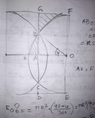
For (auto) adjustment of the extrudate next to the previously laid one I use a calculation of the squeezed area and set the Infill Width over Thickness (ratio) parameter in the Inset tab in Skeinforge, as shown bellow (apologies for the crappy sketch and photo). The calculation assumes plastic that gets squeezed by the previously laid thread flows to the empty "valley" space, and solves for equal "squeeze" and "valley" areas (the ones shown in hatch lines), but does not compensate for the effects of viscosity, e.g. not allowing plastic to flow in the hollow space under the laid extrudate:
EDIT: A rectangular section model produces accumulating errors that are the cause of most of the problems with quality and part dimensions. It's too simplistic to be used for anything other than a hollow cube, in my opinion, and observation of the actual extrudate proves that. I cannot really think of a reason for a simplistic rectangular model to be an issue for such a discussion.
Edited 4 time(s). Last edit at 06/10/2014 04:55PM by dzach.
--------------------------------------------------------
3D extruder performance tests
dzach's ORDbot Hadron build
The following animations show a model like the one nophead was referring to, and how it changes with varying W/T and layer Thickness.

W/T varying while keeping layer thickness (T) fixed.

Thickness varying while keeping W/T fixed.
For (auto) adjustment of the extrudate next to the previously laid one I use a calculation of the squeezed area and set the Infill Width over Thickness (ratio) parameter in the Inset tab in Skeinforge, as shown bellow (apologies for the crappy sketch and photo). The calculation assumes plastic that gets squeezed by the previously laid thread flows to the empty "valley" space, and solves for equal "squeeze" and "valley" areas (the ones shown in hatch lines), but does not compensate for the effects of viscosity, e.g. not allowing plastic to flow in the hollow space under the laid extrudate:

EDIT: A rectangular section model produces accumulating errors that are the cause of most of the problems with quality and part dimensions. It's too simplistic to be used for anything other than a hollow cube, in my opinion, and observation of the actual extrudate proves that. I cannot really think of a reason for a simplistic rectangular model to be an issue for such a discussion.
Edited 4 time(s). Last edit at 06/10/2014 04:55PM by dzach.
--------------------------------------------------------
3D extruder performance tests
dzach's ORDbot Hadron build
|
Re: Help, internal size of part(s) too small... June 10, 2014 04:44PM |
Admin Registered: 17 years ago Posts: 7,879 |
> You say that if W/T = 1 the output is a cylinder, but of which size if you add your normally expressed svelling factor?
The diameter of the cylinder is simply defined by flow rate over feed rate when W/T <=1. Die swell or nozzle diameter have have no effect on it or rectilinear dimensions, but they do affect curves. As the animations above show when T < W it is always squashed to a rectangle with semicircular ends. One equations holds for all values of T <= W.
> if less than 1 it could never be a cylinder could it ?
Yes when the nozzle is higher than W it falls from the nozzle and lies in a cylinder. (slightly flattened on the bottom due to gravity but that becomes negligible when T is substantially less than W, which it has to be when extruding outlines).
>After all the effort above in this thread i think it would be a pity if this was not tested with some viable solutions now offered by developer of Slic3R, and it may be up to us as users whether this came close to a solution for some of the problems with 3d printers, but do not think that any problem with size is solved with this, so more carefull design is still a vital essence to avoid problems.
I have tested this maths with Skeinforge for many years. I never have problems with dimensions. As well as this you need to account for shrinkage due to the plastic contracting but nothing else is needed to get things the right size, (assuming your axes are accurate and ignoring round holes).
Edited 1 time(s). Last edit at 06/10/2014 04:44PM by nophead.
[www.hydraraptor.blogspot.com]
|
Re: Help, internal size of part(s) too small... June 10, 2014 05:05PM |
Registered: 11 years ago Posts: 296 |
I would never take an animation as a fact sheet, but it looks of course impressive, but hardly showing reality.
I do not think that this animation would show different if a rectangle math was used, we are talking about volumen here going through extruder and the diffence in using rectangle or rounded rectangle is a minor difference in my opinion with this in mind.
Interpretion of layout is of course important, but i do not understand why you think it is a major diference to the result greater than all other factors , but as you mentioned it is a never ending discusion and I cannot add more facts to this than mentioned above.
I am looking forward to see if new Slic3R is moving anything, otherwise i am sure @sound would listen one more time to any facts describing this experience.
Edited 1 time(s). Last edit at 06/10/2014 05:07PM by justcurious.
|
Re: Help, internal size of part(s) too small... June 10, 2014 06:59PM |
Registered: 12 years ago Posts: 88 |
For a picture of reality, one can extrude a length of plastic in a single layer (or better in multiple layers) and then take a knife and make a cut across it. By observing the result with a magnifying glass or with a microscope one can be persuaded 100% about the shape of the extrudate. The animation above simply shows the result of the underlying math for the calculation of 4-5 of the parameters that are important during the extruding process, taking a round sided rectangle as a model that closely fits reality, nothing more.
The amount of plastic being squeezed as it is laid, and therefore the shape it takes, is not a minor difference; it is what makes it bond with the rest of the plastic and gives the parts their strength and appearance. If you try to have an infill of 100%, you will see what it means to have "accumulated error" in the form of accumulated plastic, making the nozzle plow into it. A simple rectangular model, if I understand correctly what the term means, cannot closely approximate "amount of squeeze" because, it seems to me, it oversimplifies or ignores the very fact of plastic being squeezed side-to-side, for the sake of simplicity. It may well be simpler geometrically, but why would one bother with this kind of simplicity? one only does the maths once.
Edited 1 time(s). Last edit at 06/10/2014 07:02PM by dzach.
--------------------------------------------------------
3D extruder performance tests
dzach's ORDbot Hadron build
|
Re: Help, internal size of part(s) too small... June 10, 2014 07:12PM |
Admin Registered: 17 years ago Posts: 7,879 |
>I would never take an animation as a fact sheet, but it looks of course impressive, but hardly showing reality.
It illustrates that when you squeeze a bead of plastic between two flat surfaces the ends are a constant semicircle due to surface tension. Why would the shape of the ends change when you change the flow rate?
I believe it shows reality and I have done experiments and never found my theory to be wrong. I have also used Slic3r, Kisslicer and Cura and never printed anything the right size. The explanation is that they assume the filament is rectangular. In the case of Slic3r this is explicitly stated in the documentation for the case where the flat top of the extrusion is less than the nozzle aperture.
Yes the errors get small when the layer height is small but it is certainly significant when you print thick layers. Also is seems Slic3r flips through several equations and actually only uses the correct one when the flat part of the extrusion is wider than the nozzle. I.e. when W - T > nozzle. I don't think I ever set W as wide as the nozzle plus the layer height because as T decreases I reduce W towards the nozzle size.
It is sub optimal to have W bigger than it needs to be as it reduces the minimum feature size and when the layer height is low it needs a lot of pressure to spread it a lot wider than the nozzle. Conversely when T is big it takes two much stretching to keep W close to the nozzle width.
[www.hydraraptor.blogspot.com]
|
Re: Help, internal size of part(s) too small... June 10, 2014 07:16PM |
Registered: 12 years ago Posts: 88 |
Oh, and here is the reason I did all the above with Skeinforge:
http://forums.reprap.org/read.php?263,134103,137818#msg-137818
--------------------------------------------------------
3D extruder performance tests
dzach's ORDbot Hadron build
http://forums.reprap.org/read.php?263,134103,137818#msg-137818
--------------------------------------------------------
3D extruder performance tests
dzach's ORDbot Hadron build
|
Re: Help, internal size of part(s) too small... June 11, 2014 02:46AM |
Registered: 11 years ago Posts: 296 |
@dzach- it would be easier to discusss if you also read what other people are adding to this discussion.
If you read the slic3r documentation that was added by @sound here: [manual.slic3r.org], you would see that for a standard user the "correct" math is used with rounded rectangles and only if W/T<1 another model (rectangle) is used.
I might think that not many pepole other than Nophead is using a flow where width is smaller than nozzle width, but if that is what it takes to get better results, why not, but saying that Slic3r is doing wrong here is to go easy with facts?
Your animation is impressive but does not show anything about geometries if W/T<1
|
Re: Help, internal size of part(s) too small... June 11, 2014 05:17AM |
Admin Registered: 17 years ago Posts: 7,879 |
Quote
justcurious
If you read the slic3r documentation that was added by @sound here: [manual.slic3r.org], you would see that for a standard user the "correct" math is used with rounded rectangles and only if W/T<1 another model (rectangle) is used.
If W/T <= 1 it is completely wrong because it uses a rectangle when it is actually a cylinder. The document even states that in the section on bridging and that is pretty much the only time you would use W/T = 1 and never any less.
Quote
justcurious
I might think that not many pepole other than Nophead is using a flow where width is smaller than nozzle width, but if that is what it takes to get better results, why not, but saying that Slic3r is doing wrong here is to go easy with facts?
Your animation is impressive but does not show anything about geometries if W/T<1
I never print with W/T<1.5 as parts would be too weak. But I nearly always print with W -T < nozzle, which is where Sound uses the "rectangle + shrunk half circles formula which is also incorrect. I don't think many people print in the region W - T >= nozzle where he use the correct formula. For example with a 0.5mm nozzle and 0.2mm layers you would need a width > 0.7mm.to get the right flow.
Edited 3 time(s). Last edit at 06/11/2014 05:19AM by nophead.
[www.hydraraptor.blogspot.com]
|
Re: Help, internal size of part(s) too small... June 11, 2014 05:46AM |
Registered: 13 years ago Posts: 228 |
Let's be clear: Slic3r considers extrusions to be generally rectangles with semicircle ends like this:
However I don't think that the extrudate gets that shape for any extruded volume. The relationship between extruded volume and extrusion width at some point changes for several other reasons.
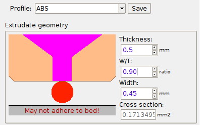
I made a screenshot of dzach's animation:
In my opinion this screenshot is wrong. I can't believe this diagram represent anything possible in physical reality. Plastic flow comes top down and fits the entire nozzle. I don't see why would it fill just a little portion of the orifice. There's pressure in the nozzle.
Do you really think this drawing is correct? Do you really think the cross sectional area for width = nozzle diameter can be calculated like that?

However I don't think that the extrudate gets that shape for any extruded volume. The relationship between extruded volume and extrusion width at some point changes for several other reasons.
I made a screenshot of dzach's animation:

In my opinion this screenshot is wrong. I can't believe this diagram represent anything possible in physical reality. Plastic flow comes top down and fits the entire nozzle. I don't see why would it fill just a little portion of the orifice. There's pressure in the nozzle.

Do you really think this drawing is correct? Do you really think the cross sectional area for width = nozzle diameter can be calculated like that?
|
Re: Help, internal size of part(s) too small... June 11, 2014 06:43AM |
Admin Registered: 17 years ago Posts: 7,879 |
Yes that drawing is correct. When the nozzle is higher than the width it is no longer shaping the top of the filament and you get a cylinder as you yourself state when bridging. When W <= T it is exactly the same as a bridge except it is supported underneath.
I think your confusion is that the drawing shows a cross section of the nozzle and a cross section of the resulting extrudate together, not a section of what the extrudate would look like at the centre of the nozzle. The filament comes out the nozzle as a vertical cylinder and then bends through 90 degrees to lay down as a horizontal cylinder.
In the general case it is always a cylinder the size of the nozzle just as it exits but it is a viscous liquid that gets pressed between the surface below and the trailing edge of the nozzle, which is also a flat surface. If you inject plastic between two flat surfaces it forms a rectangle with semicircular ends.
[www.hydraraptor.blogspot.com]
|
Re: Help, internal size of part(s) too small... June 11, 2014 07:15AM |
Registered: 12 years ago Posts: 88 |
Needless to, but I will anyway, say that I have great respect for developers of open source software and hardware, and sincere appreciation of their work that helps me and thousands other users achieve their goals. That includes Sound, Nophead and many others. My comments were meant to show how I solved the problem of wrong hole dimentsions I had back in 2012, and forgot about it ever after.
Regarding the animations:
I don't claim to have found the perfect model for the shape of the plastic as it exits the nozzle and gets deposited on the bed, next to the plastic laid previously there. The animations, which come out of a program I wrote back in 2012 to automate setting up Skeinforge for different values of layer Thickness, filament Width and printing Speed, show exactly the results of the formulas I used. The animation detail Sound picked up,is outside the range of W/T I use for printing. It is exactly for that reason that I use W/T > 1.5, a ratio at which the formulas I used start to fit closely the shape of the plastic. Bellow that ratio my, and others', experience shows that bonding of the extruded filament is very weak. To make bonding stronger I even print (ABS) at significantly higher temperatures, usually scarifying part aesthetics for a stronger part.
Looking positively into this issue:
It would be nice for user understanding of the slicing settings if splicing programs, like Slic3r, had graphics, like the above, that showed what exactly their internal model thinks that happens to the plastic, so educated adjustments could be made to the slicing parameters, instead of blindly spending hundreds of hours in futile trial and error efforts.
It surely helped me get a basic understanding of the process and achieve practical results.
Edited 1 time(s). Last edit at 06/11/2014 07:15AM by dzach.
--------------------------------------------------------
3D extruder performance tests
dzach's ORDbot Hadron build
|
Re: Help, internal size of part(s) too small... June 11, 2014 07:27AM |
Registered: 11 years ago Posts: 369 |
Do you mean like this?:
The only case I can imagine where the sides could be straight would be the cross-section down the middle of the nozzle, where we are essentially extruding a vertical cylinder of plastic for the miniscule time before it hits the surface below and gets dragged out into a horizontal line.
For printing purposes I think we are more interested in the cross-section as it leaves the trailing edge of the nozzle (nozzle aperture removed to illustrate that this is the trailing edge):
At this point, the plastic is securely adhered to the plate/object below and the movement of the nozzle/bed has dragged the plastic into the squashed cylinder that Chris describes.
Thinking about this in an even finer level of detail, is the behaviour of the filament as it is dragged through 90 degrees significant? Will there be a compression factor caused by forcing the material through 90 degrees?
Also, what about the fact that the nozzle is round rather than square?; the middle of the trailing edge will be in contact with the top of the filament for longer than the edges for any given (straight) cross-section - could die swell cause the edges of the flattened cylinder to curl upwards a tiny amount?

The only case I can imagine where the sides could be straight would be the cross-section down the middle of the nozzle, where we are essentially extruding a vertical cylinder of plastic for the miniscule time before it hits the surface below and gets dragged out into a horizontal line.
For printing purposes I think we are more interested in the cross-section as it leaves the trailing edge of the nozzle (nozzle aperture removed to illustrate that this is the trailing edge):

At this point, the plastic is securely adhered to the plate/object below and the movement of the nozzle/bed has dragged the plastic into the squashed cylinder that Chris describes.
Thinking about this in an even finer level of detail, is the behaviour of the filament as it is dragged through 90 degrees significant? Will there be a compression factor caused by forcing the material through 90 degrees?
Also, what about the fact that the nozzle is round rather than square?; the middle of the trailing edge will be in contact with the top of the filament for longer than the edges for any given (straight) cross-section - could die swell cause the edges of the flattened cylinder to curl upwards a tiny amount?
|
Re: Help, internal size of part(s) too small... June 11, 2014 07:33AM |
Registered: 12 years ago Posts: 88 |
Quote
nophead
I think your confusion is that the drawing shows a cross section of the nozzle and a cross section of the resulting extrudate together, not a section of what the extrudate would look like at the centre of the nozzle. The filament comes out the nozzle as a vertical cylinder and then bends through 90 degrees to lay down as a horizontal cylinder.
I think you are right. I'll try to correct the graphic so it shows a (section of a) vertical cylinder connected to a (section of a) horizontal one at the end. But this will not change the formulas used, just the appearance of the graphic.
EDIT: Thinking of it, the problem still exists when trying to draw the shape of the filament as T becomes more than W, in which case the filament becomes a bridge, which is a horizontal cylinder whose shape depends on the speed of extrusion. But this is more than the graphic was intended to do.
Edited 1 time(s). Last edit at 06/11/2014 07:45AM by dzach.
--------------------------------------------------------
3D extruder performance tests
dzach's ORDbot Hadron build
|
Re: Help, internal size of part(s) too small... June 11, 2014 07:35AM |
Admin Registered: 17 years ago Posts: 7,879 |
> It is exactly for that reason that I use W/T > 1.5, a ratio at which the formulas I used start to fit closely the shape of the plastic.
The general formula works all the way down to W = T because the rectangular part shrinks to zero and the two semicircular ends then form a circle. As I keep saying there is only one formula needed for calculating the relationship between flow rate and outline width. Does anybody have any experimental evidence that contradicts this formula? There may be some second order effects like gravity causing the bottom flat to be a bit longer than the top, etc, but it is accurate enough for FFF printing and more accurate than assuming the semicircular ends degenerate into rectangular ones as the width reduces. They definitely don't do that. In fact the opposite happens. The wider the filament is compared to its height the less significant the semicircles are.
[www.hydraraptor.blogspot.com]
|
Re: Help, internal size of part(s) too small... June 11, 2014 08:00AM |
Registered: 12 years ago Posts: 88 |
Here is my concern:
In doing the calculation of the cross section of the area of the filament outside the nozzle, I'll have to correct the graphic and make it detach earlier from the bed, assuming speed doesn't change. That is, I'll have to reduce the size of the circle to compensate for the area missing in the connection of the vertical (cylinder) rectangle with the (horizontal cylinder) circle. I guess I made a compromise when drawing the graphic (EDIT) and concentrated to the filament shape as it is laid on the bed instead of its picture as it leaves the nozzle. Actually, the extruder and nozzle are there just to show the height (Thickness) setting and do not take part in any calculation.
Edited 5 time(s). Last edit at 06/11/2014 08:18AM by dzach.
--------------------------------------------------------
3D extruder performance tests
dzach's ORDbot Hadron build
|
Re: Help, internal size of part(s) too small... June 11, 2014 08:02AM |
Registered: 11 years ago Posts: 296 |
I think it would be nice for any programmer if one formula could do the job and from the above discussion i may believe that this would work as good as any other as many other factors probably have greater influence.
In my opinion many users generally have no clue on how to adjust W/T and certainly not why, that is the impression I get from forums. That is why it is good to have the program select autoadjustment, and for other users to take responsibility of selecting own values, but i am not sure programs generally is good to set limits to choice of params for best results.Trial and error is what get results mostly.
Concluded from the above thread, from the start, i think that it has been verified that Slic3R selects correct path as expected and for W/T>1 it is probably selecting proper flow as well. question is would flow be better for W/T=1 and W/T<1 if the same formula was used? I do not know. i do not even know if the formula used at present version is failing!
if i should always select W/T=1.5 i would certainly get in troubles. my nozzle is 0.35 and I mostly print at 0.2mm that would say that if W/T should be 1,5, I should select extrusion width of 0.3mm, but what if i select layerheight of 0.1mm? that would give me extrusion width of 0.15mm, that does not make sense, does it? and it does probably not care which formula is used anyway.
Could anybody clarify my frustrations?
|
Re: Help, internal size of part(s) too small... June 11, 2014 08:18AM |
Admin Registered: 17 years ago Posts: 7,879 |
Quote
Concluded from the above thread, from the start, i think that it has been verified that Slic3R selects correct path as expected and for W/T>1 it is probably selecting proper flow as well. question is would flow be better for W/T=1 and W/T<1 if the same formula was used? I do not know. i do not even know if the formula used at present version is failing!
No Sli3r only uses the correct formula when W - T > nozzle.
Quote
if i should always select W/T=1.5 i would certainly get in troubles. my nozzle is 0.35 and I mostly print at 0.2mm that would say that if W/T should be 1,5, I should select extrusion width of 0.3mm, but what if i select layerheight of 0.1mm? that would give me extrusion width of 0.15mm, that does not make sense, does it? and it does probably not care which formula is used anyway.
Could anybody clarify my frustrations?
No W/T = 1.5 is only appropriate for high layer heights. In fact it the smallest value that works and together with the dies swell diameter determines the maximum layer height that you can use.
W should always be >= nozzle, so with a 0.1mm layer and 0.35mm nozzle it should be close to 0.35mm. To get the correct math in slic3r W would have to be > 0.35mm + 0.1mm, i.e. 0.45mm. W/T = 4.5.
[www.hydraraptor.blogspot.com]
|
Re: Help, internal size of part(s) too small... June 11, 2014 08:23AM |
Registered: 12 years ago Posts: 88 |
Quote
QuackingPlums
For printing purposes I think we are more interested in the cross-section as it leaves the trailing edge of the nozzle (nozzle aperture removed to illustrate that this is the trailing edge):
At this point, the plastic is securely adhered to the plate/object below and the movement of the nozzle/bed has dragged the plastic into the squashed cylinder that Chris describes.
Yes, that was the intention. So, different coloring of the extruder internals may make it clearer:

Edited 2 time(s). Last edit at 06/11/2014 08:38AM by dzach.
--------------------------------------------------------
3D extruder performance tests
dzach's ORDbot Hadron build
|
Re: Help, internal size of part(s) too small... June 11, 2014 08:43AM |
Registered: 11 years ago Posts: 296 |
Thankyou for clarifying Nophead, you are an endless source of information :-).
However it frustrates me that I see different rules for different setups and for some selections you are left in grey areas.
you did not answer my question whether you think Slic3r would be performing more correct for W/T<1 if the same algorhitm was used, but if you always select extrusion width greater than nozzlewidth it of course is nothing but a theorethical question with no practical value, is that correct?
We somehow were untracked here so let us get back to the original issue of object sizes and the new possibilities that Slic3R is offering with latest version despite the above discussion on performance of algorhitms:
1. XY size compensation, i wonder how that is going to be used for solving problems mentioned above or is it not needed, now we know that more carefull selection of params eliminate problems ;-).
2. variabel external perimeter extrusion width, which may have influence on dimensional print accuracy.
|
Re: Help, internal size of part(s) too small... June 11, 2014 08:58AM |
Registered: 12 years ago Posts: 88 |
Quote
dzach
a ratio at which the formulas I used start to fit closely the shape of the plastic.
That was a wrong statement, indeed. At lower ratios the filament continues to be pressed by the nozzle, which still gives it the rounded rectangle shape. Things change when W /T < 1, or when W > flat bottom of nozzle. Which, I think, puts the limits of the practical extrudate Width sizes to "nozzle orifice diameter" <= W <= "nozzle flat bottom diameter".
EDIT:
... a fact that is indicated in the same dynamic graphic, but not shown in the above animation (it been so long ago I had forgotten about it)

Edited 4 time(s). Last edit at 06/11/2014 09:16AM by dzach.
--------------------------------------------------------
3D extruder performance tests
dzach's ORDbot Hadron build
|
Re: Help, internal size of part(s) too small... June 11, 2014 09:04AM |
Admin Registered: 17 years ago Posts: 7,879 |
Quote
justcurious
you did not answer my question whether you think Slic3r would be performing more correct for W/T<1 if the same algorhitm was used, but if you always select extrusion width greater than nozzlewidth it of course is nothing but a theorethical question with no practical value, is that correct?
W/T can't be less than 1, i.e. you cannot extrude a filament taller than it is wide. W = T means the filament is not squashed at all and makes a cylinder. It is only relevant when bridging. Slic3r's documentation is self contradictory as it shows a cylinder in the bridge section but also shows a square in the flow section.
Quote
justcurious
We somehow were untracked here so let us get back to the original issue of object sizes and the new possibilities that Slic3R is offering with latest version despite the above discussion on performance of algorhitms:
1. XY size compensation, i wonder how that is going to be used for solving problems mentioned above or is it not needed, now we know that more carefull selection of params eliminate problems ;-).
Well you always need an overall X Y scale factor to compensate for shrinkage. It can't compensate for flow rate calculation errors as they create an offset in dimension, not a multiplier. There would be no flow rate to width errors if the right formula was used throughout to relate the two. Then it could either reduce the flow rate to give the desired width or use the same flow rate and offset by the predicted width. That would fix all error not due to shrinkage.
Quote
justcurious
2. variabel external perimeter extrusion width, which may have influence on dimensional print accuracy.
Don't know exactly what is meant by this.
Edited 1 time(s). Last edit at 06/11/2014 09:05AM by nophead.
[www.hydraraptor.blogspot.com]
|
Re: Help, internal size of part(s) too small... June 11, 2014 09:24AM |
Registered: 11 years ago Posts: 296 |
@nophead
I would be surprised if @sound is introducing scaling as a solution to above problems, i would rather believe it is some sort of inset feature, but I have not seen any description yet.
The extra parameter offered is just another variable I believe for experimenting. You already had settings for perimeter extrusion width, now you get an extra for specific setting of external perimeter (if I understand it correctly)
Edited 1 time(s). Last edit at 06/11/2014 10:41AM by justcurious.
|
Re: Help, internal size of part(s) too small... June 12, 2014 06:19PM |
Registered: 13 years ago Posts: 43 |
Quote
nophead
Quote
Concluded from the above thread, from the start, i think that it has been verified that Slic3R selects correct path as expected and for W/T>1 it is probably selecting proper flow as well. question is would flow be better for W/T=1 and W/T<1 if the same formula was used? I do not know. i do not even know if the formula used at present version is failing!
No Sli3r only uses the correct formula when W - T > nozzle.
For the sake of argument, couldn't you fudge slic3r's configuration and set a really small nozzle to get slic3r to use correct math? For example, let's assume you set the nozzle size to 0.1mm (regardless of your actual nozzle size), set layer height (T) to 0.4mm and set all extrusion widths (W) to 0.6mm. Then you'd have W/T = 1.5, and you're tricking slic3r into using your ideal formula, right? Does that give you correct sizes? If people start doing this and get correct sizes as a result, while getting wrong sizes when using slic3r normally, that'd make a strong argument for changing slic3r's formulas.
If you try this, slic3r will give you some error messages because extruding at layer heights way greater than the nozzle diameter probably wouldn't work all that great, but for the experiment you could comment out lines 254 through 257 in lib/Slic3r/Config.pm to trick it into accepting these anyway:
#    die "--layer-height can't be greater than --nozzle-diameter\n"
#        if grep $self->layer_height > $_, @{$self->nozzle_diameter};
#    die "First layer height can't be greater than --nozzle-diameter\n"
#        if grep $self->get_value('first_layer_height') > $_, @{$self->nozzle_diameter};
Regards, Ketil


Sorry, only registered users may post in this forum.