1st layer issue
Posted by ruggb
|
1st layer issue March 26, 2018 11:38AM |
Registered: 9 years ago Posts: 294 |
I just finished a bed upgrade about a week ago - 6mm MIC6 plate, 600W SI heater, PEI film
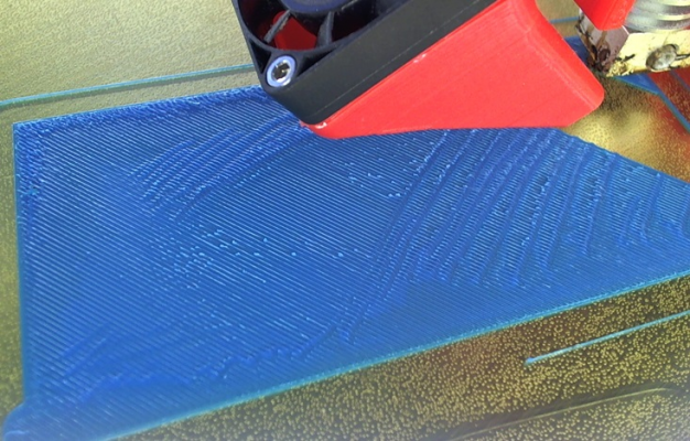
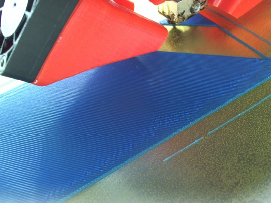
When I print ABS (maybe PLA also but I have not yet), the 1st layer is very rough.
In some places it is smooth, as if the bed has crap on it, but it does not. I use 91% iso alcohol for cleaning
The 2nd + layers print fine and I don't understand this.
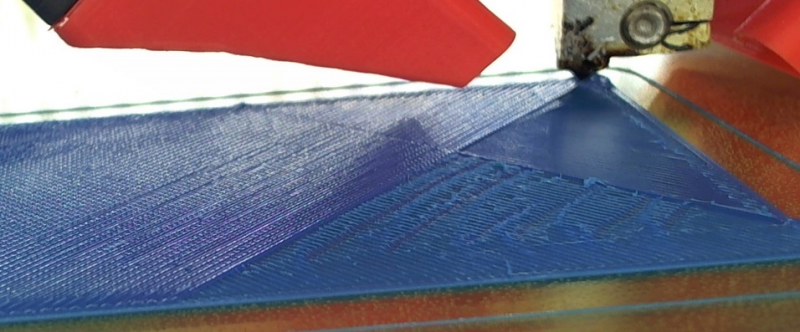
I took a few pics and posted it to the general forum, then I realized that a portion of the 1st layer was very smooth.
This corner (where the hotend is) was finished from that corner out after about 75% has been printed from the other corner.
OK, so now it looks like a Slic3r issue. 1.3.0 dev
Temps: bed = 110, hotend = 245, 250, 255 == no difference.
1st layer extrusion width = 150%, extrusion multiplier = 0.96
layer height = 0.2mm, nozzle = 0.4mm
speed = 40mm/sec, 1st layer = 60%
Any ideas?
bill
|
Re: 1st layer issue March 26, 2018 06:17PM |
Registered: 11 years ago Posts: 5,780 |
The nozzle is too close to the bed for the first layer.
Ultra MegaMax Dominator 3D printer: [drmrehorst.blogspot.com]
Ultra MegaMax Dominator 3D printer: [drmrehorst.blogspot.com]
|
Re: 1st layer issue March 26, 2018 09:02PM |
Registered: 9 years ago Posts: 294 |
thanks for the come back
When it prints the perimeters it is printing a bead - not even flattening it out.
I am surprised the PEI is holding on to it.
It is on a MIC6 plate so it should be flat. My bed leveling is 3 point and yields this matrix
1.000000, 0.000000, -0.000017
0.000000, 1.000000, 0.000043
0.000017, -0.000043, 1.000000
if it were too close to the bed, it would do it for the entire first layer - it does not.
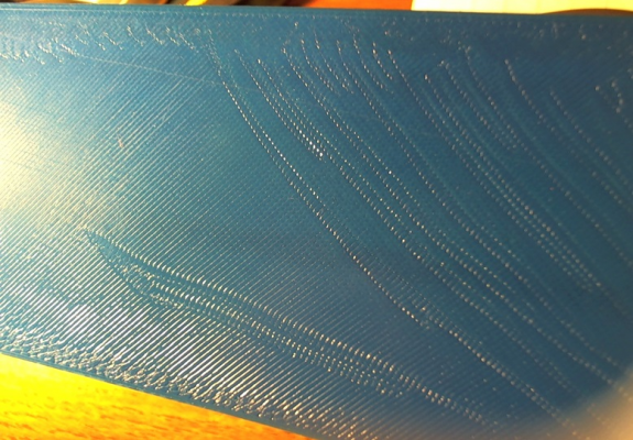
This is what the first layer looks like when it comes off the bed.
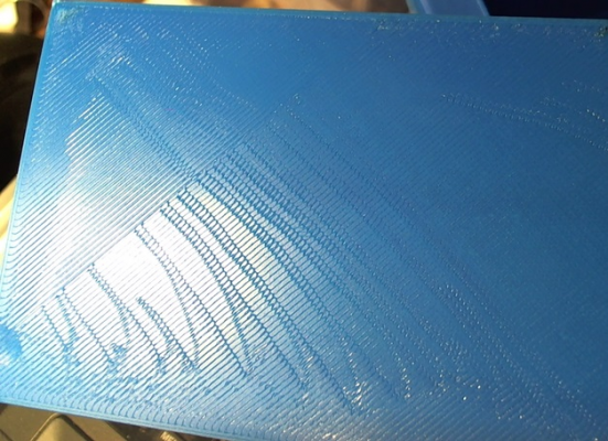
This is the previous print that started on one corner then finished the last 20% from the other corner.
The one above did the whole thing from beginning to end -- IE it didn't stop and restart from the other end.
There is something else going on here.
The PEI looks smooth - I almost thought it might be an issue with it,
but the above print looks inconsistent with that idea with that opposite corner being smooth.
Both above were printed on different parts of the bed
Edited 1 time(s). Last edit at 03/26/2018 09:04PM by ruggb.
|
Re: 1st layer issue March 27, 2018 04:03AM |
Registered: 8 years ago Posts: 5,232 |
|
Re: 1st layer issue March 27, 2018 04:55AM |
Admin Registered: 17 years ago Posts: 7,879 |
Maybe you don't wait long enough for the hot end to expand to its full length. So when it does the outline it is high but by the time it does the infill it is too low.
Plastic hot ends expand considerably when they heat up. Also some types of bed support expand.
[www.hydraraptor.blogspot.com]
Plastic hot ends expand considerably when they heat up. Also some types of bed support expand.
[www.hydraraptor.blogspot.com]
|
Re: 1st layer issue March 27, 2018 06:43AM |
Registered: 11 years ago Posts: 5,780 |
Did you peel the protective plastic film off the PEI before you tried to print on it?
Ultra MegaMax Dominator 3D printer: [drmrehorst.blogspot.com]
Ultra MegaMax Dominator 3D printer: [drmrehorst.blogspot.com]
|
Re: 1st layer issue March 27, 2018 10:41AM |
Registered: 9 years ago Posts: 294 |
Yes, the film was removed from the PEI.
My 1st layer height is 150%. Default 200% was way over but that affected the whole layer.
I am printing another - I'll get this thing right eventually.
Nothing changed. I heated the bed, then the hotend, then started the print same as before.
It is on the rear of the bed this time and about 1/2 way thru the 1st layer.
Mostly it is perfect, except on the edge toward the center of the bed.
Starting to think it has something to do with bed leveling.
Since the bed is almost perfectly level I'll have to try it with bed leveling off.
Bed leveling is purely a function of Marlin, right?
I don't know why Slic3r sometimes creates a discontinuity by finishing the 1st layer from the other corner, sometimes not.
The last print it completed from one end without the change to the other end. On the 1st & 3rd one it did its trick. Same settings in Slic3r.
I should say the model changed between prints but nothing to do with the first 3 layers.
Edited 3 time(s). Last edit at 03/27/2018 11:06AM by ruggb.
|
Re: 1st layer issue March 27, 2018 11:50AM |
Registered: 8 years ago Posts: 5,232 |
|
Re: 1st layer issue March 27, 2018 12:52PM |
Registered: 11 years ago Posts: 5,780 |
I've never understood why slicer sets layer heights using a %, and reporting a % here is meaningless without knowing a % of what.
I always set specific mm values for both layer thicknesses and line widths. It's too easy to make an error when you use percentages. I also use volumetric extrusion, leave the extrusion multiplier set to 100%, and set filament diameter to the calculated mean of 20-30 measured values.
And calibrate the snot out of the extruder!
Are you using autoleveling? With a flat plate on 3 screws it should be unnecessary.
Ultra MegaMax Dominator 3D printer: [drmrehorst.blogspot.com]
|
Re: 1st layer issue March 27, 2018 05:37PM |
Registered: 9 years ago Posts: 294 |
Quote
the_digital_dentist
I've never understood why slicer sets layer heights using a %, and reporting a % here is meaningless without knowing a % of what.
Well, if one changes the layer height from 0.2 to 0.3, using % for first layer or whatever would negate having to change many items instead of just 1. But then YMMV.
I always set specific mm values for both layer thicknesses and line widths. It's too easy to make an error when you use percentages. I also use volumetric extrusion, leave the extrusion multiplier set to 100%, and set filament diameter to the calculated mean of 20-30 measured values.
I guess it might be time to understand what Volumetric Extrusion is
And calibrate the snot out of the extruder!
Are you using autoleveling? With a flat plate on 3 screws it should be unnecessary.
I am using 3 point - it only compensates for any tilt. But I tweaked it down to those numbers so it is pretty level as it stands.
The last print looks way better when it came off the bed. Maybe it is a "feature" of the PEI.
Edited 1 time(s). Last edit at 03/27/2018 05:38PM by ruggb.
|
Re: 1st layer issue March 27, 2018 05:42PM |
Registered: 9 years ago Posts: 294 |
Quote
o_lampe
The infill starts, where the perimeter ends. That depends on the position of the part relative to the bed coords.
I was not referring to the infill. The last pic shows it printing FROM the corner it was printing TOWARD to finish the 1st layer.
It just stopped printing TOWARD the corner and restarted at the corner back to where it stopped.
BTW: looks much better now. If you need a perfect surface, acetone can smooth out a lot of crinkles or a thick layer of paint would do, too.
I don't need it perfect, just trying to understand what it is doing.
Edited 1 time(s). Last edit at 03/27/2018 05:43PM by ruggb.
|
Re: 1st layer issue March 28, 2018 11:04AM |
Registered: 11 years ago Posts: 5,780 |
Quote
ruggb
Quote
the_digital_dentist
I've never understood why slicer sets layer heights using a %, and reporting a % here is meaningless without knowing a % of what.
Well, if one changes the layer height from 0.2 to 0.3, using % for first layer or whatever would negate having to change many items instead of just 1. But then YMMV.
I always set specific mm values for both layer thicknesses and line widths. It's too easy to make an error when you use percentages. I also use volumetric extrusion, leave the extrusion multiplier set to 100%, and set filament diameter to the calculated mean of 20-30 measured values.
I guess it might be time to understand what Volumetric Extrusion is
And calibrate the snot out of the extruder!
Are you using autoleveling? With a flat plate on 3 screws it should be unnecessary.
I am using 3 point - it only compensates for any tilt. But I tweaked it down to those numbers so it is pretty level as it stands.
The last print looks way better when it came off the bed. Maybe it is a "feature" of the PEI.
Yeah that's my whole point about the % thing. You change one item and it affects several at once. I feel like it's better to change things to specific values that I know and understand than to tweak something and maybe have one or more other things end up out of range. When it comes to print settings, after you've used the printer for a while, you'll settle on speeds, line widths and layer thicknesses that work for most prints and you'll have minimal print settings to adjust. Until you have worked out those settings, it's best to control everything manually and change things one at a time until you understand exactly how each setting affects the print. Save the profiles with meaningful names so that once you find that magic combo of settings that works reliably, you can reload it over and over. After that all you'll usually have to adjust is infill and support settings. I have a few print setting profiles that I might use on each printer, usually based on a combo of speed and nozzle size. I have found that this works well at the makerspace, too, where we have a lot of people who are new to 3D printing and will be overwhelmed by all the slicer settings. I have them start with the basic profile and then tweak only the stuff that matters for their print (which has its own learning curve).
Volumetric extrusion makes the gcode insensitive to filament diameter. That means if you want to reprint something using a different color filament (which will also be different diameter), you'll get consistent results without reslicing for a new filament diameter. It requires knowing the filament diameter beyond the nominal 1.75 mm marked on the spool. I measure in 30 places, calculate the average and mark that on the spool. I use that diameter when I print (use M200 command to set diameter from host software, or enter it directly using LCD with smoothieware). You can achieve the same result using the nominal diameter to slice and then tweaking the flow control when you print- for some printers that can be set using the LCD panel. If you prefer the flow control method, when you get a new spool you make a test print sliced with the diameter set to 1.75 mm. Measure the print and calculate the flow setting to get target line width. Mark the flow setting on the spool. I would not recommend setting both the diameter and playing with the flow control. You'll never know what the extruder is doing and it will be hard to get consistent results. A lot of people babysit their prints and keep tweaking flow control and speed while the print is running. As far as I'm concerned, if you have to babysit the print and tweak settings while the print is running, you're not using the slicer options well.
When you calibrate the extruder, it is critical to slice with the known filament diameter (measure and calculate). If you don't know how big the filament is going into the extruder, how can you know what's going to come out?
All this careful measurement and calibration seems like excessive work to some people, but controlling variables is the only way to get accurate and precise results. If you just want to print Yoda heads, you don't need it, but if you want to make mechanical parts that actually fit together with each other and with other parts, you have to put in the work up front.
Calibration and volumetric extrusion are explained here: [reprap.org] Pay careful attention to the fine e-steps calibration.
Ultra MegaMax Dominator 3D printer: [drmrehorst.blogspot.com]
Sorry, only registered users may post in this forum.
