Large gaps in infill on random layers
Posted by p40whk
|
Large gaps in infill on random layers February 04, 2019 05:42PM |
Registered: 10 years ago Posts: 45 |
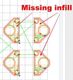
Hopefully this is just something I'm doing wrong in my settings but Slic3r will leave large gaps in the infill on random layers.
When I examine the 2D layer by layer I notice that it doesn't fill some areas of the model on some layers. Rotating the part fixes it for that layer but the dead spots show up in other layers. I noticed this while printing and not sure how to fix it
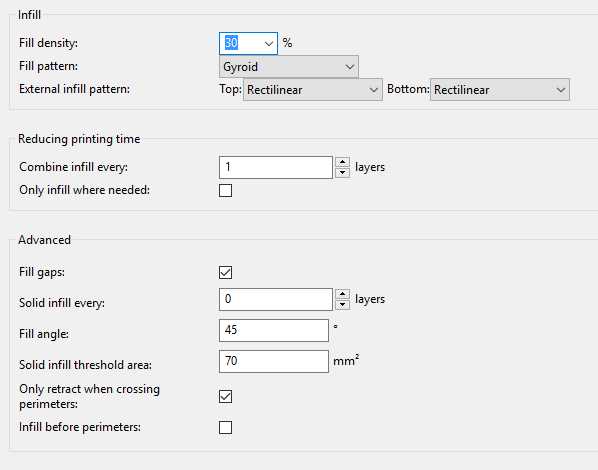
I'm printing PETG with an E3V6 Volcano and .6 nozzle, my infill settings are attached as well as a pic of the issue;
When I examine the 2D layer by layer I notice that it doesn't fill some areas of the model on some layers. Rotating the part fixes it for that layer but the dead spots show up in other layers. I noticed this while printing and not sure how to fix it
I'm printing PETG with an E3V6 Volcano and .6 nozzle, my infill settings are attached as well as a pic of the issue;
|
Re: Large gaps in infill on random layers February 05, 2019 10:01AM |
Registered: 11 years ago Posts: 5,780 |
It's probably a function of the geometry of the gyroid infill pattern, or a bug in the code that generates it. Why are you using gyroid infill?
Gyroid and hex infill are most useful for marketing photos of 3D printers, and for the guys who wrote the code to generate those patterns to show other programmers how good they are.
If you want strong infill that prints relatively quickly, use grid or triangles- both consist of long straight lines that print quickly and don't shake the crap out of your printer.
Ultra MegaMax Dominator 3D printer: [drmrehorst.blogspot.com]
|
Re: Large gaps in infill on random layers February 05, 2019 10:17AM |
Registered: 10 years ago Posts: 45 |
Honestly, I was using gyroid because a few people recommended it as being good for strong prints but if it's not the best option then I'll switch. I didn't notice the problem with other patterns. I'll be putting brass nut inserts into the PETG so I was looking for a fill pattern that would be best for that. I'm using 4 perimeters to help give me stronger prints and give more for the nut plates to bite into but went with the gyroid pattern because of recommendations.
|
Re: Large gaps in infill on random layers February 05, 2019 11:58AM |
Registered: 11 years ago Posts: 5,780 |
You should probably look into "modifier meshes" if you're going to install brass inserts. They allow you to specify regions to be printed at 100% (or any other value) infill and would be better structures to insert brass fittings.
See: [slic3r.org]
You can generate the meshes in the slicer or in your CAD file, and then export them as (a) separate stl file(s).
If the modifier mesh shares a surface with the main part, the print will include an outline of the modifier mesh on its surface, so be sure to put the modifier mesh entirely inside the main part being printed. When I use such meshes, I usually generate them in CAD and export the modifiers as separate stl files. I position the meshes at least 1 layer deep inside the main part. If the mesh is on the side wall, and line with is 0.4mm, I put the mesh at least 0.4 mm inside the print. If the print layers are 0.2mm thick and I'm using a mesh that interfaces with the top or bottom of a print I put the mesh at least 0.2mm inside the print.
Ultra MegaMax Dominator 3D printer: [drmrehorst.blogspot.com]
Sorry, only registered users may post in this forum.