Need help with endstop setup
Posted by 4Stroke
|
Need help with endstop setup January 30, 2014 04:01PM |
Registered: 10 years ago Posts: 39 |
Hi,
I act a little bit like a fool when it comes to setting up the endstops... so hopefully anybody can tell, how the correct setup for my Prusa i2 would be like.
I use mechanical endstops and connected NC to (S) on my Rumba, and C to (-). Thats ok, no?
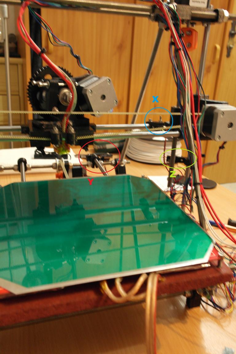
There's a picture attached from the front of my Prusa, the Y- endstop gets hit if the beds travels away to the end; the X-endstop gets hit if it moves all the way to the right, and the Z-endstop gets hit if it moves all the way downwards.
How would the correct code be, so that all endstops work for homing the reprap?
Edited 3 time(s). Last edit at 01/31/2014 03:03PM by 4Stroke.
Ein Schlosser ohne Hammer ist ein Jammer, ein Schlosser ohne Feile geht 'ne Weile
I act a little bit like a fool when it comes to setting up the endstops... so hopefully anybody can tell, how the correct setup for my Prusa i2 would be like.
I use mechanical endstops and connected NC to (S) on my Rumba, and C to (-). Thats ok, no?
There's a picture attached from the front of my Prusa, the Y- endstop gets hit if the beds travels away to the end; the X-endstop gets hit if it moves all the way to the right, and the Z-endstop gets hit if it moves all the way downwards.
How would the correct code be, so that all endstops work for homing the reprap?
Edited 3 time(s). Last edit at 01/31/2014 03:03PM by 4Stroke.
Ein Schlosser ohne Hammer ist ein Jammer, ein Schlosser ohne Feile geht 'ne Weile
|
Re: Need help with endstop setup January 31, 2014 03:08PM |
Registered: 10 years ago Posts: 39 |
I believe I figured out the right settings for my endstops. Z-endstop is working fine, but something is still wrong with the X und Y axis.
In idle, all endstops show (L), if I type in M119. If the Z-endstop gets hit, the terminal will show me (H) for Z and it won't move downwards anymore.
If the X and Y axis hit their endstops, the terminal also shows a (H), but they can still be moved in that direction.
Anybody an idea, why X and Y can still move allthough the endstops say (H)?
Thats my code:
Ein Schlosser ohne Hammer ist ein Jammer, ein Schlosser ohne Feile geht 'ne Weile
In idle, all endstops show (L), if I type in M119. If the Z-endstop gets hit, the terminal will show me (H) for Z and it won't move downwards anymore.
If the X and Y axis hit their endstops, the terminal also shows a (H), but they can still be moved in that direction.
Anybody an idea, why X and Y can still move allthough the endstops say (H)?
Thats my code:
#define ENDSTOP_PULLUP_X_MIN true
#define ENDSTOP_PULLUP_Y_MIN true
#define ENDSTOP_PULLUP_Z_MIN true
#define ENDSTOP_PULLUP_X_MAX true
#define ENDSTOP_PULLUP_Y_MAX true
#define ENDSTOP_PULLUP_Z_MAX true

//set to true to invert the logic of the endstops
#define ENDSTOP_X_MIN_INVERTING false
#define ENDSTOP_Y_MIN_INVERTING false
#define ENDSTOP_Z_MIN_INVERTING false
#define ENDSTOP_X_MAX_INVERTING false
#define ENDSTOP_Y_MAX_INVERTING false
#define ENDSTOP_Z_MAX_INVERTING false

// Set the values true where you have a hardware endstop. The Pin numbe ris taken from pins.h.

#define MIN_HARDWARE_ENDSTOP_X false
#define MIN_HARDWARE_ENDSTOP_Y true
#define MIN_HARDWARE_ENDSTOP_Z true
#define MAX_HARDWARE_ENDSTOP_X true
#define MAX_HARDWARE_ENDSTOP_Y false
#define MAX_HARDWARE_ENDSTOP_Z false

//If your axes are only moving in one direction, make sure the endstops are connected properly.
//If your axes move in one direction ONLY when the endstops are triggered, set ENDSTOPS_INVERTING to true here


//// ADVANCED SETTINGS - to tweak parameters

// For Inverting Stepper Enable Pins (Active Low) use 0, Non Inverting (Active High) use 1
#define X_ENABLE_ON 0
#define Y_ENABLE_ON 0
#define Z_ENABLE_ON 0

// Disables axis when it's not being used.
#define DISABLE_X false
#define DISABLE_Y false
#define DISABLE_Z false
#define DISABLE_E false

// Inverting axis direction
#define INVERT_X_DIR true
#define INVERT_Y_DIR true
#define INVERT_Z_DIR true

//// ENDSTOP SETTINGS:
// Sets direction of endstops when homing; 1=MAX, -1=MIN
#define X_HOME_DIR 1
#define Y_HOME_DIR -1
#define Z_HOME_DIR -1

// Delta robot radius endstop
#define max_software_endstop_r true

//If true, axis won't move to coordinates less than zero.
#define min_software_endstop_x false
#define min_software_endstop_y false
#define min_software_endstop_z false

//If true, axis won't move to coordinates greater than the defined lengths below.
#define max_software_endstop_x true
#define max_software_endstop_y true
#define max_software_endstop_z true

// If during homing the endstop is reached, ho many mm should the printer move back for the second try
#define ENDSTOP_X_BACK_MOVE 5
#define ENDSTOP_Y_BACK_MOVE 5
#define ENDSTOP_Z_BACK_MOVE 2

// For higher precision you can reduce the speed for the second test on the endstop
// during homing operation. The homing speed is divided by the value. 1 = same speed, 2 = half speed
#define ENDSTOP_X_RETEST_REDUCTION_FACTOR 2
#define ENDSTOP_Y_RETEST_REDUCTION_FACTOR 2
#define ENDSTOP_Z_RETEST_REDUCTION_FACTOR 2

// When you have several endstops in one circuit you need to disable it after homing by moving a
// small amount back. This is also the case with H-belt systems.
#define ENDSTOP_X_BACK_ON_HOME 1
#define ENDSTOP_Y_BACK_ON_HOME 14
#define ENDSTOP_Z_BACK_ON_HOME 0

// You can disable endstop checking for print moves. This is needed, if you get sometimes
// false signals from your endstops. If your endstops don't give false signals, you
// can set it on for safety.
#define ALWAYS_CHECK_ENDSTOPS false

// maximum positions in mm - only fixed numbers!
// For delta robot Z_MAX_LENGTH is maximum travel of the towers and should be set to the distance between the hotend
// and the platform when the printer is at its home position.
// If EEPROM is enabled these values will be overidden with the values in the EEPROM
#define X_MAX_LENGTH 150
#define Y_MAX_LENGTH 162
#define Z_MAX_LENGTH 80

// Coordinates for the minimum axis. Can also be negative if you want to have the bed start at 0 and the printer can go to the left side
// of the bed. Maximum coordinate is given by adding the above X_MAX_LENGTH values.
#define X_MIN_POS 0
#define Y_MIN_POS 0
#define Z_MIN_POS 0
Ein Schlosser ohne Hammer ist ein Jammer, ein Schlosser ohne Feile geht 'ne Weile
|
Re: Need help with endstop setup February 01, 2014 02:13AM |
Registered: 10 years ago Posts: 341 |
I'm not quite sure what you mean. Are you just playing with them to make sure they are reporting the correct values if closed or open, or are the steppers not stopping when the endstop is triggered when you home the axis?
I see you have this setting: #define ALWAYS_CHECK_ENDSTOPS false which as i understand (i might be wrong here), will only check the endstops during the homing sequence, after all axis is homed, it doesn't check the endstop status until its told to rehome. If you set that to true you will probably get the result you are looking for. EDIT: Only set to true if you really need/want this, as stated in the comments make sure you know your endstops won't pickup any interference and trigger a false hit mid print.
If the steppers don't stop when hitting the enstops during the homing sequence, then make sure they are wired correctly and plugged into the correct connector on the board.
Edited 1 time(s). Last edit at 02/01/2014 02:19AM by sdavi.
Sorry, only registered users may post in this forum.