Novato desesperado¡
Posted by rafetalay
|
Novato desesperado¡ March 25, 2016 08:56AM |
Registered: 8 years ago Posts: 13 |
 Hola a todos mi nombre es Rafa,
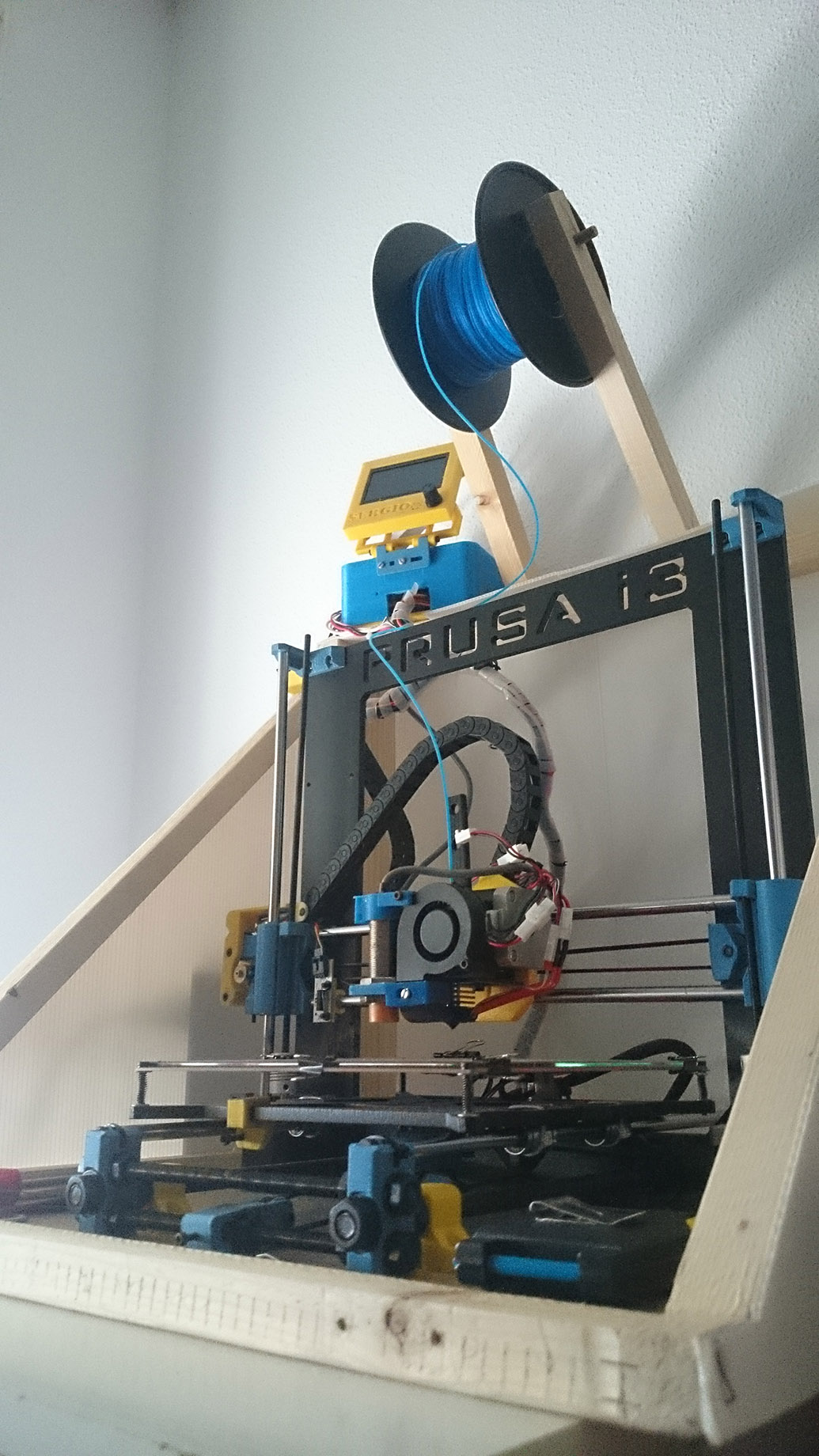
Iré al grano, he comprado a un tipo una prusa i3 hephestos mejorada , con lcd alta resolución , sensor capacitativo, y caja aislante, y en teoria era enchufarla e impirimir, pero cuando tenia que empezar a imprimir fallaba el sensor del eje z.
Listo yo, decido modificar el firmware , reseteando todo inclusive el lcd que dejó de funcionar....encima jamás había tocado una impresora y el tipo no tiene el firmware modificado.
La cuestíon que ya tengo casi todo calibrado de nuevo,el eje X se mueve como toca y hace home. El eje Y se mueve como toca pero al decirle home, el final de carrera se activa cuando llega al final pero el motor no se para.
Los endsstops con m119 los tengo abiertos o cerrados correctamente comprobados.
Y llegado a este punto ya no se por donde tirar , ¿algún alma caritativa que me muestre algo de luz?
Este es el código principal:
// Uncomment the following line to enable CoreXY kinematics
// #define COREXY
// coarse Endstop Settings
#define ENDSTOPPULLUPS // Comment this out (using // at the start of the line) to disable the endstop pullup resistors
#ifndef ENDSTOPPULLUPS
// fine endstop settings: Individual pullups. will be ignored if ENDSTOPPULLUPS is defined
//#define ENDSTOPPULLUP_XMAX
//#define ENDSTOPPULLUP_YMAX
//#define ENDSTOPPULLUP_ZMAX
//#define ENDSTOPPULLUP_XMIN
//#define ENDSTOPPULLUP_YMIN
// #define ENDSTOPPULLUP_ZMIN
#endif
#ifdef ENDSTOPPULLUPS
#define ENDSTOPPULLUP_XMAX
#define ENDSTOPPULLUP_YMAX
#define ENDSTOPPULLUP_ZMAX
#define ENDSTOPPULLUP_XMIN
#define ENDSTOPPULLUP_YMIN
//#define ENDSTOPPULLUP_ZMIN
#endif
// The pullups are needed if you directly connect a mechanical endswitch between the signal and ground pins.
const bool X_MIN_ENDSTOP_INVERTING = true; // set to true to invert the logic of the endstop.
const bool Y_MIN_ENDSTOP_INVERTING = true; // set to true to invert the logic of the endstop.
const bool Z_MIN_ENDSTOP_INVERTING = false; // set to true to invert the logic of the endstop.
const bool X_MAX_ENDSTOP_INVERTING = true; // set to true to invert the logic of the endstop.
const bool Y_MAX_ENDSTOP_INVERTING = true; // set to true to invert the logic of the endstop.
const bool Z_MAX_ENDSTOP_INVERTING = true; // set to true to invert the logic of the endstop.
//#define DISABLE_MAX_ENDSTOPS
//#define DISABLE_MIN_ENDSTOPS
// Disable max endstops for compatibility with endstop checking routine
#if defined(COREXY) && !defined(DISABLE_MAX_ENDSTOPS)
#define DISABLE_MAX_ENDSTOPS
#endif
// For Inverting Stepper Enable Pins (Active Low) use 0, Non Inverting (Active High) use 1
#define X_ENABLE_ON 0
#define Y_ENABLE_ON 0
#define Z_ENABLE_ON 0
#define E_ENABLE_ON 0 // For all extruders
// Disables axis when it's not being used.
#define DISABLE_X true
#define DISABLE_Y true
#define DISABLE_Z true
#define DISABLE_E false // For all extruders
#define DISABLE_INACTIVE_EXTRUDER true //disable only inactive extruders and keep active extruder enabled
#define INVERT_X_DIR false // for Mendel set to false, for Orca set to true
#define INVERT_Y_DIR false // for Mendel set to true, for Orca set to false
#define INVERT_Z_DIR false // for Mendel set to false, for Orca set to true
#define INVERT_E0_DIR false // for direct drive extruder v9 set to true, for geared extruder set to false
#define INVERT_E1_DIR false // for direct drive extruder v9 set to true, for geared extruder set to false
#define INVERT_E2_DIR false // for direct drive extruder v9 set to true, for geared extruder set to false
// ENDSTOP SETTINGS:
// Sets direction of endstops when homing; 1=MAX, -1=MIN
#define X_HOME_DIR -1
#define Y_HOME_DIR 1
#define Z_HOME_DIR -1
#define min_software_endstops true // If true, axis won't move to coordinates less than HOME_POS.
#define max_software_endstops true // If true, axis won't move to coordinates greater than the defined lengths below.
Graciass por adelantado¡¡¡
|
Re: Novato desesperado¡ March 25, 2016 03:28PM |
Registered: 8 years ago Posts: 2 |
|
Re: Novato desesperado¡ March 25, 2016 04:05PM |
Registered: 9 years ago Posts: 242 |
Como dijieron fijate como está configurado. En RAMPS hay 6 conectores para endstops XMAX XMIN y así para los 3 ejes. Cuando hacés el M119 tienen que coincidir con la ubicación que le diste en la impresora... por ejemplo en una I3 si el endstop está a la izquierda sería XMIN, si el de Y está atrás sería YMIN (eso porque el cero está normalmente en el extremo de adelante a la izquierda en las camas). Corroborá eso, y si el motor cuando dejas todo bien va para el otro lado, invertilo en marlin o da vuelta los conectores...
Saludos!
Saludos!
|
Re: Novato desesperado¡ March 27, 2016 08:12PM |
Registered: 8 years ago Posts: 13 |
|
Re: Novato desesperado¡ March 28, 2016 08:27AM |
Registered: 8 years ago Posts: 13 |
Os cuento, lo cambio a -1 y en lugar de ir hacia el MIN , va hacia el MAX, cuando yo el endstop lo tengo en el MIN, por eso lo deje en 1.
El problema es que el endstop se activa correctamente pero no se detiene el motor. En los RAMPS están conectados en los MIN X e Y, y Z con el inductivo. En teoría está todo bien porque antes de que los borrara accidentalmente el firmware funcionaba todo como tocaba menos el sensor z, con lo que por lógica el endstop del eje y debería estar funcionando bien si lo configuro bien.
El problema es que el endstop se activa correctamente pero no se detiene el motor. En los RAMPS están conectados en los MIN X e Y, y Z con el inductivo. En teoría está todo bien porque antes de que los borrara accidentalmente el firmware funcionaba todo como tocaba menos el sensor z, con lo que por lógica el endstop del eje y debería estar funcionando bien si lo configuro bien.
|
Re: Novato desesperado¡ March 28, 2016 10:32AM |
Registered: 9 years ago Posts: 78 |
Ponelo en -1 e invertí el sentido de giro del motor.
El 1 lo configura para buscar YMax, pero si esta mal el sentido del motor se mueve hacia Ymin. Entonces al activarse Ymin no le da bola porque esta buscando el max.
Para ser más prolijo, si no tenes max Endstops desactivalos desde el firmware, decomentando la linea
//#define DISABLE_MAX_ENDSTOPS
Edited 1 time(s). Last edit at 03/28/2016 10:33AM by tikey.
|
Re: Novato desesperado¡ March 29, 2016 07:30AM |
Registered: 8 years ago Posts: 13 |
|
Re: Novato desesperado¡ March 30, 2016 07:13AM |
Registered: 8 years ago Posts: 13 |
Hola , ya he probado lo de invertir el sentido del motor y hace Home correctamente ¡¡¡ El endstops funciona¡¡ pero cuando lo quiero mover en una dirección el eje Y se mueve en la contraria ¿eso no afectará a las impresiones?
Después he intentado hacer un home con Z pero me dice "echo:Home X/Y before Z"....los hago antes pero nada...no me hace el Home con Z y el sensor inductivo, sigo probando....
Edited 1 time(s). Last edit at 03/30/2016 07:45AM by rafetalay.
Después he intentado hacer un home con Z pero me dice "echo:Home X/Y before Z"....los hago antes pero nada...no me hace el Home con Z y el sensor inductivo, sigo probando....
Edited 1 time(s). Last edit at 03/30/2016 07:45AM by rafetalay.
|
Re: Novato desesperado¡ March 30, 2016 08:31AM |
Registered: 9 years ago Posts: 78 |
A ver ¿Qué impresora tenes?
Lo único que se me ocurre que, o estas interpretando mal el sentido de movimiento del motor o colocaste el endstop en el otro extremo. El firmware aparentemente funciona como corresponde. ¿Tenes fotos de la maquina? ¿Que soft de control estas usando? ¿Repetier, pronterface?
Lo único que se me ocurre que, o estas interpretando mal el sentido de movimiento del motor o colocaste el endstop en el otro extremo. El firmware aparentemente funciona como corresponde. ¿Tenes fotos de la maquina? ¿Que soft de control estas usando? ¿Repetier, pronterface?
|
Re: Novato desesperado¡ March 30, 2016 11:10AM |
Registered: 8 years ago Posts: 13 |
|
Re: Novato desesperado¡ March 30, 2016 05:22PM |
Registered: 9 years ago Posts: 242 |
Hola, mira a veces lo mejor es arrancar desde cero evitando posibles errores acumulados. Te cuento como los suelo configurar (suelo hacer pruebas usar motores reciclados, etc, por lo que siempre tengo que chequear todo)
1ro. Conecto todo, antes de prender la impresora pongo todos los recorridos en el centro para evitar problemas.
2do. Con M119 analizo si los endstops están bien conectados/configurados en marlin.
Ubicación en la impresora:
EJE X: Izquierda XMIN y/o derecha XMAX
EJE Y: atraz YMIN y/o delante YMAX
EJE Z: abajo ZMIN y/o arriba ZMAX
Luego de verificar ESO configuro en Marlin el home_DIR para que coincida... (aca no hay vueltas, el cero debería estar a la izquierda si el endstop está a la derecha va a ser MAX y hay que configurarlo así si está al revez, puede andar pero luego a lo mejor el día que quiera imprimir un texto me va a salir espejado)
sin mover nada solo verifico que con todo sin apretar estén en open y si voy apretando de a 1, la salida del M119 me de bien.
3ro. CON CUIDADO DE PODER APAGAR LA IMPRESORA si algo va para el otro lado o con el boton de kill si tengo display tiro un G28 (home)
Si el motor va para el lado del ENDSTOP configurado, está OK, sino apago la impresora y o invierto el conector del motor en RAMPS o utilizo la linea en marlin o repetier para invertir la dirección... luego vuelvo a probar para que todos los ejes estén ok.
4to. Con el home andando correctamente recién ahi voy y configuro el area de impresion y demas en marlin...
Las únicas cosas para tener en cuenta: es todo mas facil si se siguen los pinouts standard de ramps. (o sea si es MIN hay un pin y si es MAX hay otro, se pueden después cambiar por firmware, pero a la larga puede ser un lio hacer un debug) y otra es que una impresora andando por ejemplo con una versión vieja de Marlin, si la pasas al nuevo validar el procedimiento desde cero, porque a veces se cambia si hace el pullup o como viene por defecto la logica invertida o no.
Si se te complica (no creo que sea algo mecanico ni electronico si el M119 te funciona, te recomendaría bajar una versión limpia de marlin y probar desde cero)
Saludos y suerte!!!
|
Re: Novato desesperado¡ March 31, 2016 07:29AM |
Registered: 8 years ago Posts: 13 |
Bueno de momento ya es un logro que X e Y , me hagan Home correctamente, ahora sigo averiguando lo del eje z, que para mi es más fácil que empezar de cero , si consigo saber porque no me hace el Home el eje z creo que ya podré empezar a realizar las primeras pruebas de impresión¡
Si no lo consigo tal vez empiece de cero con otro Marlin, pero no dispongo de tanto tiempo jejeje.
Gracias a todos por los consejos y ayuda¡ Sigo intentándolo y os cuento en cuanto pueda¡

Si no lo consigo tal vez empiece de cero con otro Marlin, pero no dispongo de tanto tiempo jejeje.
Gracias a todos por los consejos y ayuda¡ Sigo intentándolo y os cuento en cuanto pueda¡
|
Re: Novato desesperado¡ March 31, 2016 07:46AM |
Registered: 9 years ago Posts: 78 |
|
Re: Novato desesperado¡ April 01, 2016 07:21AM |
Registered: 8 years ago Posts: 13 |
|
Re: Novato desesperado¡ April 01, 2016 08:04AM |
Registered: 9 years ago Posts: 78 |
|
Re: Novato desesperado¡ April 01, 2016 10:57AM |
Registered: 8 years ago Posts: 13 |
|
Re: Novato desesperado¡ April 04, 2016 03:59PM |
Registered: 8 years ago Posts: 13 |
Bueno tras poder hacer unas pruebas os cuento:
Intenté imprimir con Cura por pura curiosidad a pesar de que no he podido hacer Home con el Z , que tiene un sensor inductivo.Pues cual fue mi sorpresa? que imprime¡¡¡ pero mal claro jejeje puse a imprimir el cubo de Bq de 20mm y me ha salido algo parecido pero de 10 mm y a mitad de impresión se me obstruyo el extrusor que tuve que limpiar después.
Así que todo apunta a que solo es un tema de firmware que me falta ajustar algunas cosas, la pregunta es ¿alguno de vosotros tiene un Marlin configurado para una hephestos con sensor inductivo que me pueda dejar? es que ya no se que más buscar y probar¡
Aquí os dejo la prueba.
Deciros que para imprimir eliminé del Cura la linea donde dice hacer Home X e Y,por que si nos me imprimía en una esquina, y así me imprime donde lo dejo yo por defecto en el centro y con Z ajustado para q pase una hoja de papel.
Sobre todo tengo que saber porq no me hace Home z y ajustar lo que me falte para imprimir correctamente.
Gracias a todos ¡ Seguimos luchando¡
Edited 2 time(s). Last edit at 04/04/2016 05:43PM by rafetalay.
Intenté imprimir con Cura por pura curiosidad a pesar de que no he podido hacer Home con el Z , que tiene un sensor inductivo.Pues cual fue mi sorpresa? que imprime¡¡¡ pero mal claro jejeje puse a imprimir el cubo de Bq de 20mm y me ha salido algo parecido pero de 10 mm y a mitad de impresión se me obstruyo el extrusor que tuve que limpiar después.
Así que todo apunta a que solo es un tema de firmware que me falta ajustar algunas cosas, la pregunta es ¿alguno de vosotros tiene un Marlin configurado para una hephestos con sensor inductivo que me pueda dejar? es que ya no se que más buscar y probar¡
Aquí os dejo la prueba.

Deciros que para imprimir eliminé del Cura la linea donde dice hacer Home X e Y,por que si nos me imprimía en una esquina, y así me imprime donde lo dejo yo por defecto en el centro y con Z ajustado para q pase una hoja de papel.
Sobre todo tengo que saber porq no me hace Home z y ajustar lo que me falte para imprimir correctamente.
Gracias a todos ¡ Seguimos luchando¡
Edited 2 time(s). Last edit at 04/04/2016 05:43PM by rafetalay.
|
Re: Novato desesperado¡ April 04, 2016 09:26PM |
Registered: 9 years ago Posts: 242 |
Hola! el sensor ya verificaste que te marque correctamente abierto y cerrado ni bien se acerca a la cama caliente? si bien es diferente a un final de carrera mecánico, no deja de ser (logicamente) lo mismo pero accionado por la distancia a la cama. Por lo que deberías poder (a mano) bajar el eje Z hasta que la salida del M119 te de como triggered. Con eso deberías poder activar:
#define AUTO_BED_LEVELING (lo uses o no, así hace el home en el centro de la cama gracias a SAFE HOME)
luego poner los valores necesarios en:
#define X_PROBE_OFFSET_FROM_EXTRUDER 0 // X offset: -left [of the nozzle] +right
#define Y_PROBE_OFFSET_FROM_EXTRUDER 0 // Y offset: -front [of the nozzle] +behind
#define Z_PROBE_OFFSET_FROM_EXTRUDER 0 // Z offset: -below [the nozzle] (always negative!)
Por último cuando vas a imprimir, si queres usar auto level tenes que poner:
G28 XY
G29
y si no vas a usarlo, simplemente
G28
Pero antes que nada fijate que el sensor esté andando bien!!!
Saludos!
|
Re: Novato desesperado¡ April 05, 2016 01:44PM |
Registered: 8 years ago Posts: 13 |
Ok me centraré en eso, os dejo lo que tengo yo por si vierais algo raro:
#define ENABLE_AUTO_BED_LEVELING // Delete the comment to enable (remove // at the start of the line)
//#define Z_PROBE_REPEATABILITY_TEST // If not commented out, Z-Probe Repeatability test will be included if Auto Bed Leveling is Enabled.
#ifdef ENABLE_AUTO_BED_LEVELING
// There are 2 different ways to pick the X and Y locations to probe:
// - "grid" mode
// Probe every point in a rectangular grid
// You must specify the rectangle, and the density of sample points
// This mode is preferred because there are more measurements.
// It used to be called ACCURATE_BED_LEVELING but "grid" is more descriptive
// - "3-point" mode
// Probe 3 arbitrary points on the bed (that aren't colinear)
// You must specify the X & Y coordinates of all 3 points
#define AUTO_BED_LEVELING_GRID
// with AUTO_BED_LEVELING_GRID, the bed is sampled in a
// AUTO_BED_LEVELING_GRID_POINTSxAUTO_BED_LEVELING_GRID_POINTS grid
// and least squares solution is calculated
// Note: this feature occupies 10'206 byte
#ifdef AUTO_BED_LEVELING_GRID
// set the rectangle in which to probe
#define LEFT_PROBE_BED_POSITION 50
#define RIGHT_PROBE_BED_POSITION 165
#define BACK_PROBE_BED_POSITION 1650
#define FRONT_PROBE_BED_POSITION 50
// set the number of grid points per dimension
// I wouldn't see a reason to go above 3 (=9 probing points on the bed)
#define AUTO_BED_LEVELING_GRID_POINTS 2
#else // not AUTO_BED_LEVELING_GRID
// with no grid, just probe 3 arbitrary points. A simple cross-product
// is used to esimate the plane of the print bed
#define ABL_PROBE_PT_1_X 15
#define ABL_PROBE_PT_1_Y 180
#define ABL_PROBE_PT_2_X 15
#define ABL_PROBE_PT_2_Y 20
#define ABL_PROBE_PT_3_X 170
#define ABL_PROBE_PT_3_Y 20
#endif // AUTO_BED_LEVELING_GRID
// these are the offsets to the probe relative to the extruder tip (Hotend - Probe)
// X and Y offsets must be integers
#define X_PROBE_OFFSET_FROM_EXTRUDER -25
#define Y_PROBE_OFFSET_FROM_EXTRUDER -29
#define Z_PROBE_OFFSET_FROM_EXTRUDER 0.6
#define Z_RAISE_BEFORE_HOMING 4 // (in mm) Raise Z before homing (G28) for Probe Clearance.
// Be sure you have this distance over your Z_MAX_POS in case
#define XY_TRAVEL_SPEED 8000 // X and Y axis travel speed between probes, in mm/min
#define Z_RAISE_BEFORE_PROBING 15 //How much the extruder will be raised before traveling to the first probing point.
#define Z_RAISE_BETWEEN_PROBINGS 5 //How much the extruder will be raised when traveling from between next probing points
//#define Z_PROBE_SLED // turn on if you have a z-probe mounted on a sled like those designed by Charles Bell
//#define SLED_DOCKING_OFFSET 5 // the extra distance the X axis must travel to pickup the sled. 0 should be fine but you can push it further if you'd like.
//If defined, the Probe servo will be turned on only during movement and then turned off to avoid jerk
//The value is the delay to turn the servo off after powered on - depends on the servo speed; 300ms is good value, but you can try lower it.
// You MUST HAVE the SERVO_ENDSTOPS defined to use here a value higher than zero otherwise your code will not compile.
// #define PROBE_SERVO_DEACTIVATION_DELAY 300
//If you have enabled the Bed Auto Leveling and are using the same Z Probe for Z Homing,
//it is highly recommended you let this Z_SAFE_HOMING enabled!!!
#define Z_SAFE_HOMING // This feature is meant to avoid Z homing with probe outside the bed area.
// When defined, it will:
// - Allow Z homing only after X and Y homing AND stepper drivers still enabled
// - If stepper drivers timeout, it will need X and Y homing again before Z homing
// - Position the probe in a defined XY point before Z Homing when homing all axis (G28)
// - Block Z homing only when the probe is outside bed area.
#ifdef Z_SAFE_HOMING
#define Z_SAFE_HOMING_X_POINT (X_MAX_LENGTH/2) // X point for Z homing when homing all axis (G28)
#define Z_SAFE_HOMING_Y_POINT (Y_MAX_LENGTH/2) // Y point for Z homing when homing all axis (G28)
#endif
#ifdef AUTO_BED_LEVELING_GRID // Check if Probe_Offset * Grid Points is greater than Probing Range
#if X_PROBE_OFFSET_FROM_EXTRUDER < 0
#if (-(X_PROBE_OFFSET_FROM_EXTRUDER * AUTO_BED_LEVELING_GRID_POINTS) >= (RIGHT_PROBE_BED_POSITION - LEFT_PROBE_BED_POSITION))
#error "The X axis probing range is not enough to fit all the points defined in AUTO_BED_LEVELING_GRID_POINTS"
#endif
#else
#if ((X_PROBE_OFFSET_FROM_EXTRUDER * AUTO_BED_LEVELING_GRID_POINTS) >= (RIGHT_PROBE_BED_POSITION - LEFT_PROBE_BED_POSITION))
#error "The X axis probing range is not enough to fit all the points defined in AUTO_BED_LEVELING_GRID_POINTS"
#endif
#endif
#if Y_PROBE_OFFSET_FROM_EXTRUDER < 0
#if (-(Y_PROBE_OFFSET_FROM_EXTRUDER * AUTO_BED_LEVELING_GRID_POINTS) >= (BACK_PROBE_BED_POSITION - FRONT_PROBE_BED_POSITION))
#error "The Y axis probing range is not enough to fit all the points defined in AUTO_BED_LEVELING_GRID_POINTS"
#endif
#else
#if ((Y_PROBE_OFFSET_FROM_EXTRUDER * AUTO_BED_LEVELING_GRID_POINTS) >= (BACK_PROBE_BED_POSITION - FRONT_PROBE_BED_POSITION))
#error "The Y axis probing range is not enough to fit all the points defined in AUTO_BED_LEVELING_GRID_POINTS"
#endif
#endif
#endif
#endif // ENABLE_AUTO_BED_LEVELING
// The position of the homing switches
//#define MANUAL_HOME_POSITIONS // If defined, MANUAL_*_HOME_POS below will be used
//#define BED_CENTER_AT_0_0 // If defined, the center of the bed is at (X=0, Y=0)
//Manual homing switch locations:
// For deltabots this means top and center of the Cartesian print volume.
#define MANUAL_X_HOME_POS 0
#define MANUAL_Y_HOME_POS 0
#define MANUAL_Z_HOME_POS 0
//#define MANUAL_Z_HOME_POS 402 // For delta: Distance between nozzle and print surface after homing.
//// MOVEMENT SETTINGS
#define NUM_AXIS 4 // The axis order in all axis related arrays is X, Y, Z, E
#define HOMING_FEEDRATE {50*60, 50*60, 4*60, 0} // set the homing speeds (mm/min)
// default settings
#define DEFAULT_AXIS_STEPS_PER_UNIT {200,200,4000,726.7} // default steps per unit for Ultimaker
#define DEFAULT_MAX_FEEDRATE {500, 500, 5, 25} // (mm/sec)
#define DEFAULT_MAX_ACCELERATION {9000,9000,100,10000} // X, Y, Z, E maximum start speed for accelerated moves. E default values are good for Skeinforge 40+, for older versions raise them a lot.
#define DEFAULT_ACCELERATION 3000 // X, Y, Z and E max acceleration in mm/s^2 for printing moves
#define DEFAULT_RETRACT_ACCELERATION 3000 // X, Y, Z and E max acceleration in mm/s^2 for retracts
// Offset of the extruders (uncomment if using more than one and relying on firmware to position when changing).
// The offset has to be X=0, Y=0 for the extruder 0 hotend (default extruder).
// For the other hotends it is their distance from the extruder 0 hotend.
// #define EXTRUDER_OFFSET_X {0.0, 20.00} // (in mm) for each extruder, offset of the hotend on the X axis
// #define EXTRUDER_OFFSET_Y {0.0, 5.00} // (in mm) for each extruder, offset of the hotend on the Y axis
// The speed change that does not require acceleration (i.e. the software might assume it can be done instantaneously)
#define DEFAULT_XYJERK 20.0 // (mm/sec)
#define DEFAULT_ZJERK 0.4 // (mm/sec)
#define DEFAULT_EJERK 5.0 // (mm/sec)
//===========================================================================
//=============================Additional Features===========================
//===========================================================================
// Custom M code points
#define CUSTOM_M_CODES
#ifdef CUSTOM_M_CODES
#define CUSTOM_M_CODE_SET_Z_PROBE_OFFSET 851
#define Z_PROBE_OFFSET_RANGE_MIN -15
#define Z_PROBE_OFFSET_RANGE_MAX -5
#endif
|
Re: Novato desesperado¡ April 05, 2016 01:51PM |
Registered: 9 years ago Posts: 78 |

|
Re: Novato desesperado¡ April 05, 2016 02:00PM |
Registered: 8 years ago Posts: 13 |
|
Re: Novato desesperado¡ April 05, 2016 02:33PM |
Registered: 9 years ago Posts: 78 |
#define AUTO_BED_LEVELING_GRID_POINTS 2
yo lo pondría en 3 porque la verdad sino no tiene mucha diferencia con hacer un sondeo de tres puntos.
#define Z_PROBE_OFFSET_FROM_EXTRUDER 0.6
Según tengo entendido este valor debe ser negativo para que funcione, sino considera que la sonda esta por debajo del Z.
Ahora chequeando un poco la internet me parece que en todos los valores del offset tenes que cambiarle el signo (es decir, si es positivo, ponelo negativo y viceversa). No estoy del todo seguro, pero que el valor de Z va en negativo si.
Edited 1 time(s). Last edit at 04/05/2016 02:34PM by tikey.
|
Re: Novato desesperado¡ April 05, 2016 04:07PM |
Registered: 8 years ago Posts: 13 |
Si el Z lo he puesto en negativo, los otros en teoría están bien, he hecho varias pruebas copiando la configuración del autolevel de otros firmware, pero nada no consigo que haga un Home como toca, o me tira el error de que before X/Y home, pero estoy viendo que el tema gira en torno a el eje z el sensor inductivo y algún detalle más de la configuración.
Lo bueno es que pude probar a imprimir desde cura y por lo que veo no me queda tanto para poder hacer una correcta impresión, pero es difícil cuando no llevo nada más que un mes en este mundo y no he montado yo la impresora.
Ojala tuviera el firmware del que la montó¡ o alguno similar¡
Seguiremos intentándolo¡ Y de nuevo gracias a los que intentáis ayudarme¡
Edited 1 time(s). Last edit at 04/05/2016 04:10PM by rafetalay.
Sorry, only registered users may post in this forum.