Solidworks Metric Assembly
Posted by willworkforplastic
|
Solidworks Metric Assembly June 18, 2012 07:30AM |
Registered: 11 years ago Posts: 111 |
Must say this is a tidy little design, love the idea. And I have a laser cutter and 3d FDM printer at work........ Time to put down the gaming mouse and pick up the Cading one......
However not much of a fan of the evil empire that is imperial (the hate derives from the fact it is hard to get in the land of the metric kiwi) so time to re-work in good old solidworks.
However does anybody have parasolid/step etc versions of files. I tried opening the Tantillus.0.3.4.blend file and it just crashed. Others seem to open fine however.
|
Re: Solidworks Metric Assembly June 18, 2012 03:01PM |
Registered: 13 years ago Posts: 2,947 |
willworkforplastic Wrote:
-------------------------------------------------------
> Must say this is a tidy little design, love the
> idea. And I have a laser cutter and 3d FDM printer
> at work........ Time to put down the gaming mouse
> and pick up the Cading one......
>
> However not much of a fan of the evil empire that
> is imperial (the hate derives from the fact it is
> hard to get in the land of the metric kiwi) so
> time to re-work in good old solidworks.
>
> However does anybody have parasolid/step etc
> versions of files. I tried opening the
> Tantillus.0.3.4.blend file and it just crashed.
> Others seem to open fine however.
I apologize for the imperial I hate it as well. Just living in Canada makes it hard to get metric hardware even thou we are a metric country.
Did it crash in Blender? It may just have been taking a long time to render all the boolean functions. On my trusty old single core 800mhz Laptop it takes a very very long time. On my quad core 3.2ghz machine it still takes 1-2 minutes to open it if I had saved it at a point where it had to do lots of maths.
If you can not open 0.3.4 I could save the entire assembly as OBJ, or 3DS, or something else Blender is capable of exporting so you could open it in something else.
You could also try FreeCAD to convert the STL files to STEP or IGES.
Let me know if there is anything I can do to help.
| FFF Settings Calculator | Gcode post processors | Geometric Object Deposition Tool Blog |
| Tantillus.org | Mini Printable Lathe | How NOT to install a Pololu driver |
|
Re: Solidworks Metric Assembly June 25, 2012 12:08AM |
Registered: 11 years ago Posts: 111 |
Appologies for the late update, but I have been a bit sick, the doc tells me it is an epic case of Man Flu...........
Only tried blender once, figured it must be x64 system messing with it, or my Xfire setup.
So I have started modeling up laser cut version in SW. Should be there in a week or two depending how hard it is to get over this man flu.
I have a few questions but I am waiting to group them all up. Few of them have answered themselves.
However one question you may be able to help me with in the meantime:
Where is the best place to buy a hot ends and assembled electronics?
|
Re: Solidworks Metric Assembly June 25, 2012 12:15AM |
Registered: 13 years ago Posts: 2,947 |
willworkforplastic Wrote:
-------------------------------------------------------
> Where is the best place to buy a hot ends and
> assembled electronics?
All the hotends for Tantillus are being made by Brian at Hotends.com. It can use almost any groove mount hotend but I am selling them with J-head Mk-Vb and the have been run with J-head Mk-IVb as well. The first one used a homemade hotend.
I just recently started purchasing from RepRapDiscount.com and they have been great.
| FFF Settings Calculator | Gcode post processors | Geometric Object Deposition Tool Blog |
| Tantillus.org | Mini Printable Lathe | How NOT to install a Pololu driver |
|
Re: Solidworks Metric Assembly June 25, 2012 01:17AM |
Registered: 11 years ago Posts: 149 |
willworkforplastic Wrote:
-------------------------------------------------------
> So I have started modeling up laser cut version in
> SW. Should be there in a week or two depending how
> hard it is to get over this man flu.
I was planning to model the parts in SW too, so if you want to split up the work let me know. I can put in some hours this week and next.
What file type are you importing into SW? Best thing I've been able to do is import the STL's as solids and use the measuring tool to pull the dimensions. I messed around with exporting different file types from Blender for a while and read up a little on converting mesh files to solid files, but couldn't get any of the files to export/import very well. Also tried Rhino as well as some other freeware recommended on this forum thread below, but no real luck. I don't really know much at all about any of the software I was using other than SW, so I may have missed something.
[blenderartists.org]
|
Re: Solidworks Metric Assembly June 26, 2012 09:16PM |
Registered: 11 years ago Posts: 111 |
Yah, more fellow SW users!
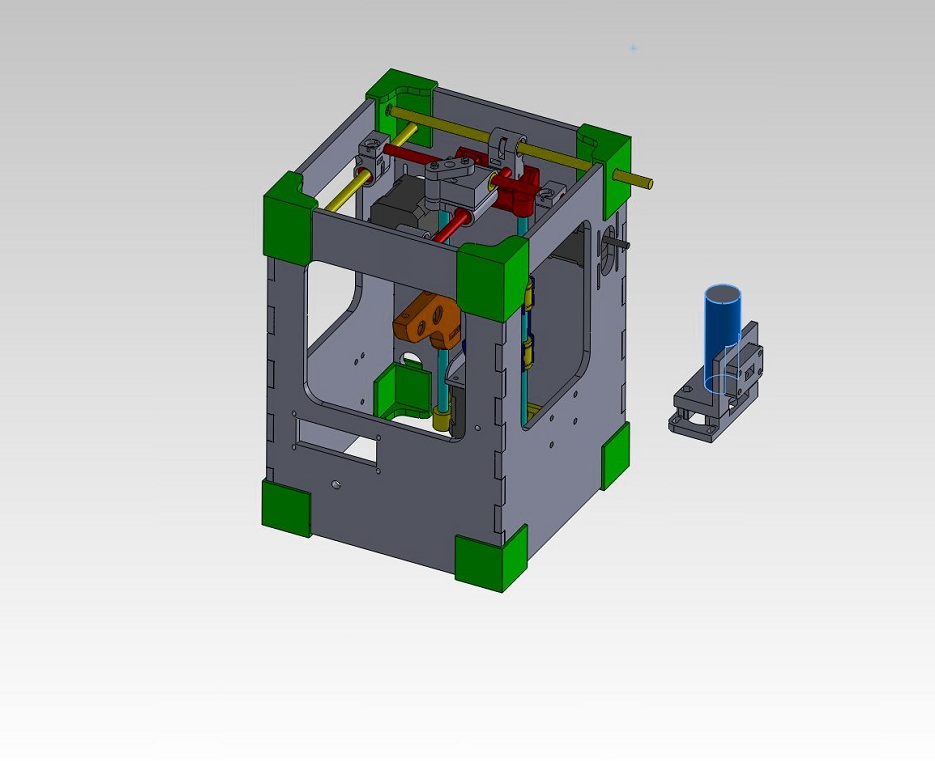
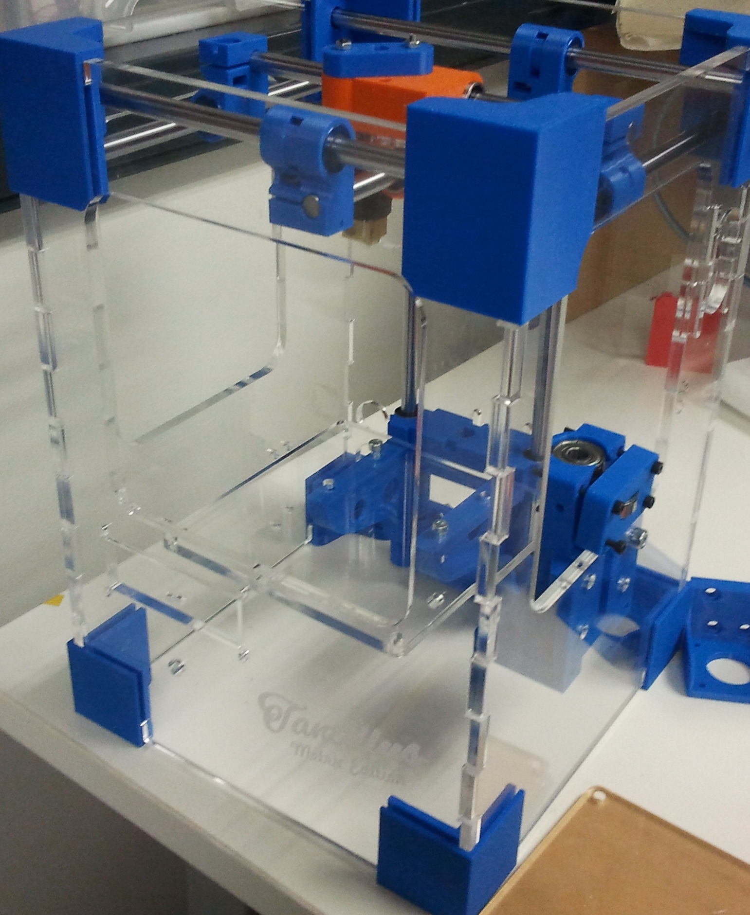
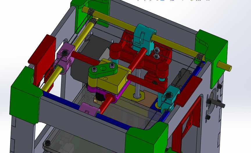
Sorry for my late reply, this man flu has been kicking my arse. I'm almost there see attached image.
Just got to do a few bits and pieces on the Z/extruder and converting bits and pieces to metric. Should be done by end of weekend.
If you can model up hot end and electronics that would be sweet.
Yes that is the way I am doing it, import STL's/DXF's as surface/solid bodies into solidworks then take measurements of the meshs.
|
Re: Solidworks Metric Assembly June 27, 2012 06:39AM |
Registered: 11 years ago Posts: 111 |
|
Re: Solidworks Metric Assembly June 27, 2012 01:02PM |
Registered: 11 years ago Posts: 149 |
Oh nice you're almost done, looks great!
Sure I'll do the gears, hot end and electronics.
Not sure which file(s) is the hot end, can you let me know? I'm new to this 3D printer stuff
A few of the gears (the 3 Motor_Gear files), won't open as solids for me because "The STL model has too many surfaces". Are you able to open those as solids? If so would you mind saving off as a SW parts and sending them? If you can't open them as solids either then maybe Sublime can cut the parts in half for us.
|
Re: Solidworks Metric Assembly June 27, 2012 01:43PM |
Registered: 11 years ago Posts: 149 |
|
Re: Solidworks Metric Assembly June 27, 2012 11:35PM |
Registered: 13 years ago Posts: 2,947 |
Eric Young Wrote:
-------------------------------------------------------
> Oh nice you're almost done, looks great!
>
> Sure I'll do the gears, hot end and electronics.
>
> Not sure which file(s) is the hot end, can you let
> me know? I'm new to this 3D printer stuff
>
> A few of the gears (the 3 Motor_Gear files), won't
> open as solids for me because "The STL model has
> too many surfaces". Are you able to open those as
> solids? If so would you mind saving off as a SW
> parts and sending them? If you can't open them as
> solids either then maybe Sublime can cut the parts
> in half for us.
They are none manifolded. Run them through cloud.nettfab.com
| FFF Settings Calculator | Gcode post processors | Geometric Object Deposition Tool Blog |
| Tantillus.org | Mini Printable Lathe | How NOT to install a Pololu driver |
|
Re: Solidworks Metric Assembly June 30, 2012 05:45AM |
Registered: 11 years ago Posts: 111 |
Eric Young Wrote:
-------------------------------------------------------
> A few of the gears (the 3 Motor_Gear files), won't
> open as solids for me because "The STL model has
> too many surfaces". Are you able to open those as
> solids? If so would you mind saving off as a SW
> parts and sending them? If you can't open them as
> solids either then maybe Sublime can cut the parts
> in half for us.
When you go to open them, click the options button in the open dialouge box, once you have set the file type to stl. Then change the open type to surface body rather than solid body. Should work then, if SW crashes, probably you are running out of ram.
I have opened them and saved them off as parasolids anyhow. They are big files though (36Mb each) so cannot attach to this post. If you still have trouble and need them tell me and I will find a way to get them to you.
|
Re: Solidworks Metric Assembly July 02, 2012 11:11AM |
Registered: 11 years ago Posts: 149 |
Was able to model the hot end and any of the electronics for which I could find dimensions. Should we stick the SW files up on Github?
For the gears I'm going to try creating a master file with linked equations and a design table so they can be easily modified, otherwise the involute tooth profiles need to get re-calculated every time someone wants to change a gear.
Sublime, are you able you tell me what variables were used to make the gears? If so do you still have the numbers you used? The pressure angles and either the diametrical pitchs or pitch diameters are really all I need and I can get the rest of the info from the STL models. If the gears were designed with a certain tolerance class then knowing what it is would help too.
|
Re: Solidworks Metric Assembly July 02, 2012 01:37PM |
Registered: 13 years ago Posts: 2,947 |
Sorry limited internet access where I am right now so the short answer is no I do not know the math involved but that is because I did not design them. The links to the originals are in the readme and on the home page of Tantillus.org. They were designed by Triffid Hunter and are for Gregs Wades extruder. The small gears for the extruder are not as mathematically correct as the large ones and should be remodelled.
| FFF Settings Calculator | Gcode post processors | Geometric Object Deposition Tool Blog |
| Tantillus.org | Mini Printable Lathe | How NOT to install a Pololu driver |
|
Re: Solidworks Metric Assembly July 02, 2012 03:58PM |
Registered: 11 years ago Posts: 149 |
Thanks Sublime. The gears in your videos seem to work nicely and that's what counts in my book
I took a look at those Triffid Hunter gears and and it looks like they're all non-involute, which may not even really matter given the tolerances/layers associated with a printed part. I'm thinking that once I have my Tantillus working I'll take a crack at modeling the all gears with involute teeth and then print/install them to see if they actually make a difference.
If the small extruder gear is causing any problems I can try to re-model it sooner rather than later, just let me know if you'd like me to.
|
Re: Solidworks Metric Assembly July 05, 2012 04:27AM |
Registered: 11 years ago Posts: 111 |
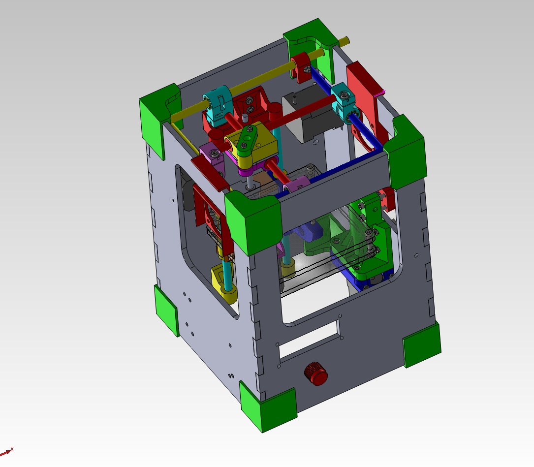
Right I have got it all (except gears and springs) into SW now, got all the laser cutting done and started on the 3d printing. Hopefully building it up will find my translation errors quickly. However I am cheating because the parts are coming of a professional FDM machine. Untill I have unit going I will not be able to print parts of a tantillus etc.
Can I post model up in the Tantillus github, or do I start a new one?
The design is good I must say. Seems sublime you have spent a lot of time thinking about things, and trying to make things simple. My hat tips to you sir.
I do however have a few things I noted (not trying to bag your design or work sublime just trying to help out):
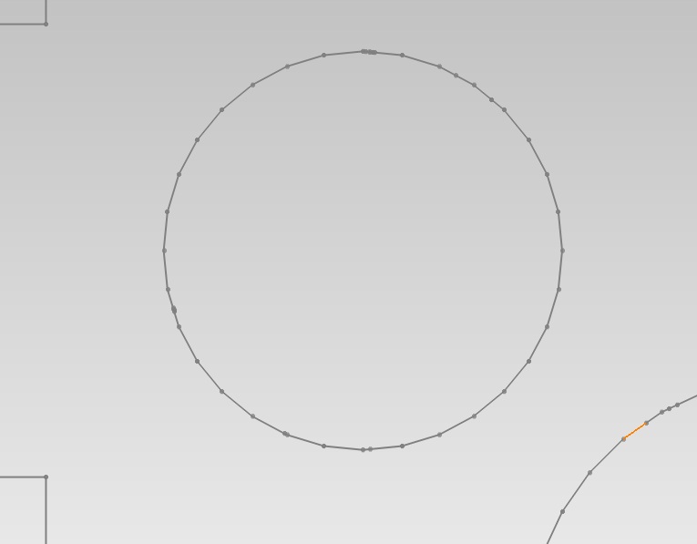
1. I noticed the orginal DXF's are segmented. That is the circles are made up of relatively large lines rather than circle elements. Probably caused by blender being a surfacing/mesh tool. While it does not probably actually matter for accuracy sake, I know it can really slow down laser cutters (job at work was taking us 5hrs when it should have been taking 1/2hr per part). Basically it is because the laser accelerates up/down per line segment, rather than constantly accelerating around the curve. Might help on cost per part if you are getting a lot of them made etc.
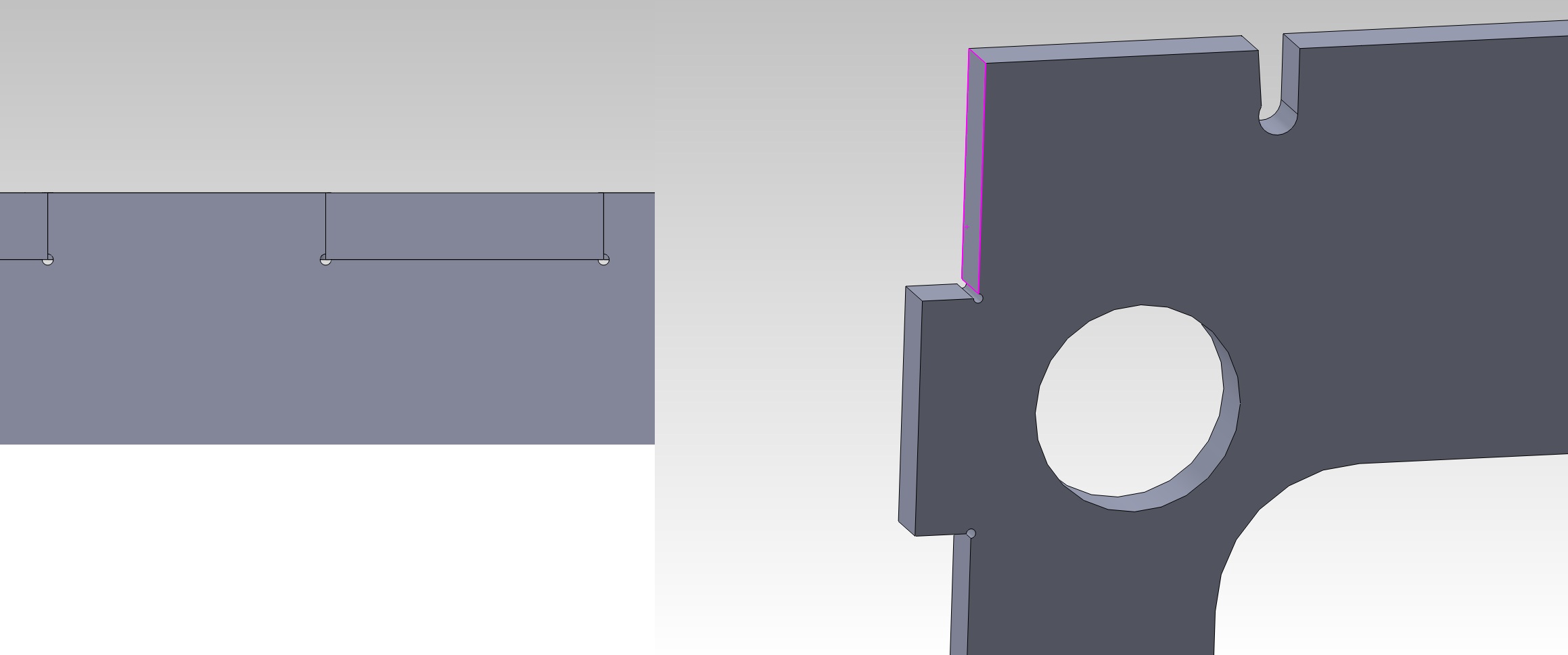
2. I have added corner relief in the tongue slots on the laser cut parts. Basically it means the laser cutter's radius does not interfer with the tongues corner. Probably not needed for plastic parts just force of habit from working with laser cut sheet metal "clip together' parts etc.
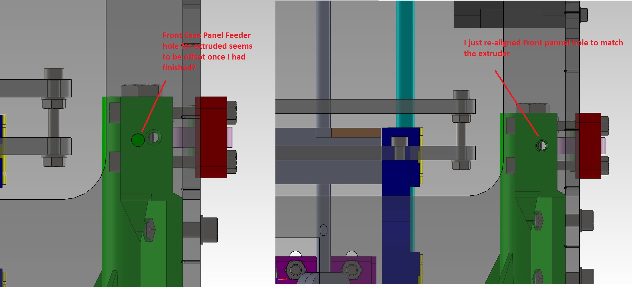
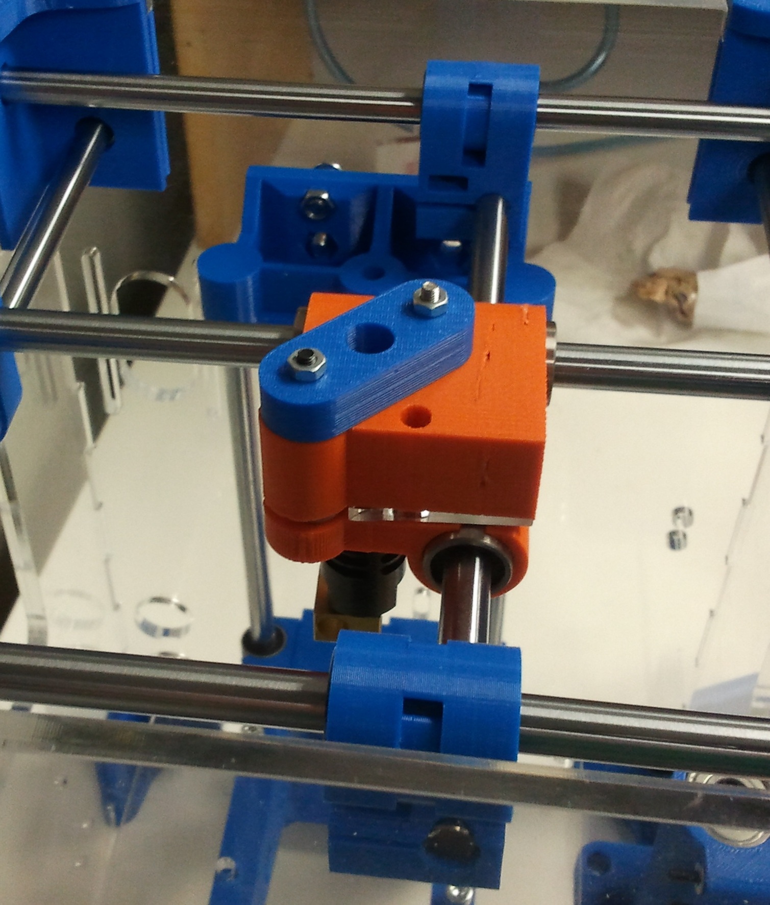
3. Front panel feeder hole was miss-aligned to extruder feed hole. Is there purpose for this, or did I translate the model incorrectly?
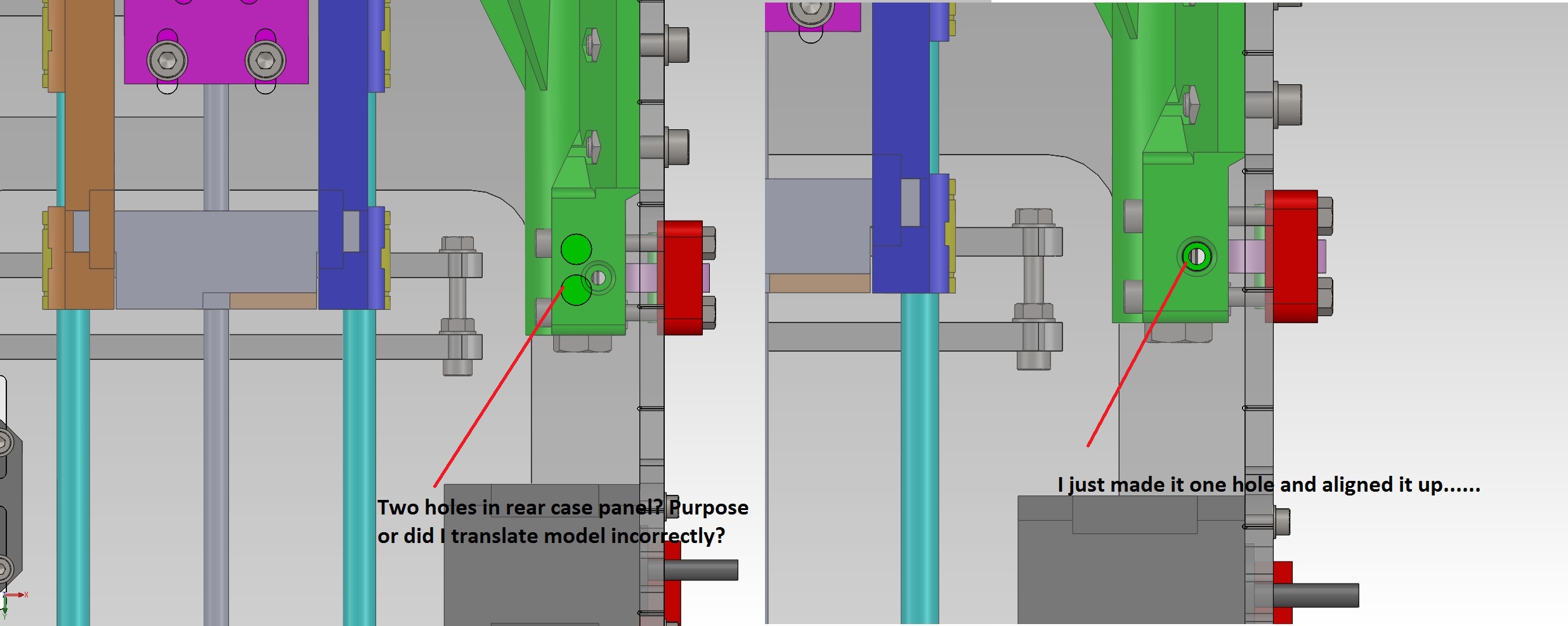
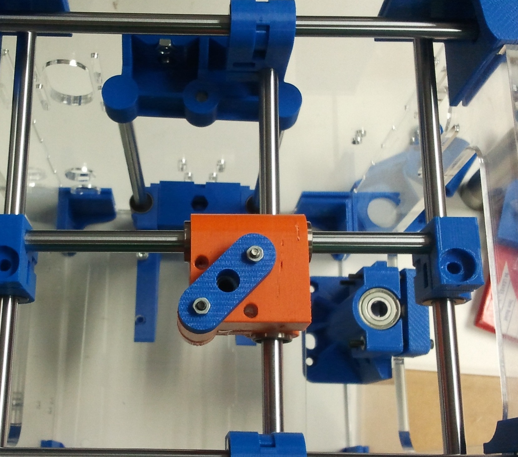
4. There where two holes in the rear pannel for the extruded material that where offset again. Is there purpose for this, or did I translate the model incorrectly again?
Pictures attached to hopefully help explain things.
Anyhow I'll update later next week with how build is going.
Can I post model up in the Tantillus github, or do I start a new one?
The design is good I must say. Seems sublime you have spent a lot of time thinking about things, and trying to make things simple. My hat tips to you sir.
I do however have a few things I noted (not trying to bag your design or work sublime just trying to help out):
1. I noticed the orginal DXF's are segmented. That is the circles are made up of relatively large lines rather than circle elements. Probably caused by blender being a surfacing/mesh tool. While it does not probably actually matter for accuracy sake, I know it can really slow down laser cutters (job at work was taking us 5hrs when it should have been taking 1/2hr per part). Basically it is because the laser accelerates up/down per line segment, rather than constantly accelerating around the curve. Might help on cost per part if you are getting a lot of them made etc.
2. I have added corner relief in the tongue slots on the laser cut parts. Basically it means the laser cutter's radius does not interfer with the tongues corner. Probably not needed for plastic parts just force of habit from working with laser cut sheet metal "clip together' parts etc.
3. Front panel feeder hole was miss-aligned to extruder feed hole. Is there purpose for this, or did I translate the model incorrectly?
4. There where two holes in the rear pannel for the extruded material that where offset again. Is there purpose for this, or did I translate the model incorrectly again?
Pictures attached to hopefully help explain things.
Anyhow I'll update later next week with how build is going.
Attachments:
open | download - Full Model.jpg (160.9 KB)
open | download - Full Model Front Case Off.jpg (145.3 KB)
open | download - DXF Segmented.jpg (21.5 KB)
open | download - Corner Relief.jpg (86.3 KB)
open | download - Front Case Feeder Hole.jpg (210.1 KB)
open | download - Rear Case Feeder Hole.jpg (272 KB)
|
Re: Solidworks Metric Assembly July 05, 2012 10:42AM |
Registered: 11 years ago Posts: 95 |
|
Re: Solidworks Metric Assembly July 05, 2012 01:24PM |
Registered: 13 years ago Posts: 2,947 |
willworkforplastic Wrote:
-------------------------------------------------------
> Right I have got it all (except gears and springs)
> into SW now, got all the laser cutting done and
> started on the 3d printing. Hopefully building it
> up will find my translation errors quickly.
> However I am cheating because the parts are coming
> of a professional FDM machine. Untill I have unit
> going I will not be able to print parts of a
> tantillus etc.
>
> Can I post model up in the Tantillus github, or do
> I start a new one?
Press the fork button and start your own. Once you have confirmed it works and can be assembled with the hardware you choose I will pull some of it to the main branch or start a metric branch.
>
> The design is good I must say. Seems sublime you
> have spent a lot of time thinking about things,
> and trying to make things simple. My hat tips to
> you sir.
I tried.
>
> I do however have a few things I noted (not trying
> to bag your design or work sublime just trying to
> help out):
No worries this is how things develop and advance.
>
> 1. I noticed the orginal DXF's are segmented. That
> is the circles are made up of relatively large
> lines rather than circle elements. Probably caused
> by blender being a surfacing/mesh tool. While it
> does not probably actually matter for accuracy
> sake, I know it can really slow down laser cutters
> (job at work was taking us 5hrs when it should
> have been taking 1/2hr per part). Basically it is
> because the laser accelerates up/down per line
> segment, rather than constantly accelerating
> around the curve. Might help on cost per part if
> you are getting a lot of them made etc.
Yes the laser cutting service was not the happiest with the segmented lines. I did redraw all the bolt holes with Inkscape so they are proper curves but did not do the bearings because I had the prototypes cut using the segmented lines and did not want to chance having the curves turn out the wrong size for the 608 bearings to fit in (very important to be a perfect fit). I would appreciate if someone makes a proper drawing with proper curves everywhere and can confirm the size work.
P.s. the reason for the segments is Blender but also it is a result of using an STL to generate the DXF's and SVG's.
>
> 2. I have added corner relief in the tongue slots
> on the laser cut parts. Basically it means the
> laser cutter's radius does not interfer with the
> tongues corner. Probably not needed for plastic
> parts just force of habit from working with laser
> cut sheet metal "clip together' parts etc.
If you are referring to the finger joints on the corners I have to say they serve very little purpose other than to keep the sides aligned. They do not hold the case together that is done by the corner connectors.
>
> 3. Front panel feeder hole was miss-aligned to
> extruder feed hole. Is there purpose for this, or
> did I translate the model incorrectly?
>
> 4. There where two holes in the rear pannel for
> the extruded material that where offset again. Is
> there purpose for this, or did I translate the
> model incorrectly again?
>
You are missing the 6mm thick spacer that goes behind the extruder. The printed case has clearance built in for the gears that stick out of the side of the extruder and the laser cut case does not so it requires a spacer.
The hole in the front is a little low because the bolt holes in the case and extruder are a little over sized to make assembly easier and it results in the extruder sitting a little lower then you have it modelled.
The two holes in the rear are for the Bowden tube and the wires. The top hole is a little above the extruder hole so the bowden tube curves properly and the lower is just set a few mm's below the upper one.
They will all need to be relocated to where I had them.
> Pictures attached to hopefully help explain
> things.
>
> Anyhow I'll update later next week with how build
> is going.
Keep us informed of the progress.
| FFF Settings Calculator | Gcode post processors | Geometric Object Deposition Tool Blog |
| Tantillus.org | Mini Printable Lathe | How NOT to install a Pololu driver |
|
Re: Solidworks Metric Assembly July 05, 2012 02:18PM |
Admin Registered: 17 years ago Posts: 7,879 |
Quote
did not want to chance having the curves turn out the wrong size for the 608 bearings to fit
What tolerance does your laser cutting service quote? I was quoted +/- 0.2mm which would be no good for an interference fit.
[www.hydraraptor.blogspot.com]
|
Re: Solidworks Metric Assembly July 05, 2012 02:32PM |
Registered: 13 years ago Posts: 2,947 |
nophead Wrote:
-------------------------------------------------------
> did not want to chance having the curves turn out
> the wrong size for the 608 bearings to fit
>
> What tolerance does your laser cutting service
> quote? I was quoted +/- 0.2mm which would be no
> good for an interference fit.
This is what I was told. I am sure the range is because it changes with the thickness of the material.
Quote
For your joins, please take into consideration the thickness of the laser beam which is about 0.2-0.35 mm.
| FFF Settings Calculator | Gcode post processors | Geometric Object Deposition Tool Blog |
| Tantillus.org | Mini Printable Lathe | How NOT to install a Pololu driver |
|
Re: Solidworks Metric Assembly July 05, 2012 03:39PM |
Admin Registered: 17 years ago Posts: 7,879 |
Yes the holes are conical in thick materials. I asked if they compensated for the kerf or if I had to do it and they replied that they did the offsetting but holes would be +/- 0.2mm, so I imagine the beam would be considerably bigger. It put the brakes on me selling Mendel90 kits because that spread is too big to tap reliably.
[www.hydraraptor.blogspot.com]
[www.hydraraptor.blogspot.com]
|
Re: Solidworks Metric Assembly July 10, 2012 06:55PM |
Registered: 11 years ago Posts: 111 |
nophead Wrote:
-------------------------------------------------------
> Yes the holes are conical in thick materials. I
> asked if they compensated for the kerf or if I had
> to do it and they replied that they did the
> offsetting but holes would be +/- 0.2mm, so I
> imagine the beam would be considerably bigger. It
> put the brakes on me selling Mendel90 kits because
> that spread is too big to tap reliably.
I find our laser cutter at work to be +/-0.1 in accuracy, but better than that in repeatibility. Way I have done it is offset the cut lines by 0.1mm (0.2mm beam spot) and then the bearing holes basically where an interferrence fit due to the angle on the cut. Then lucky I had a 22mm hand reamer lying around, ran that through the hole (clean of oil etc) and the fit was perfect.
|
Re: Solidworks Metric Assembly July 10, 2012 07:24PM |
Registered: 11 years ago Posts: 111 |
Right build is going well, just waiting on linear components and electronics now.
However I have an issue with the Hotend MKV-B that turned up. I cut the carriage middle from 6mm Acrylic just assuming that it would be the same thickness as all the other bits. However the grove on the hot end is 4.6mm, does this mean that the carriage middle is cut from 4mm arcylic?
However I have an issue with the Hotend MKV-B that turned up. I cut the carriage middle from 6mm Acrylic just assuming that it would be the same thickness as all the other bits. However the grove on the hot end is 4.6mm, does this mean that the carriage middle is cut from 4mm arcylic?
|
Re: Solidworks Metric Assembly July 10, 2012 08:01PM |
Registered: 13 years ago Posts: 2,947 |
willworkforplastic Wrote:
-------------------------------------------------------
> Right build is going well, just waiting on linear
> components and electronics now.
>
> However I have an issue with the Hotend MKV-B that
> turned up. I cut the carriage middle from 6mm
> Acrylic just assuming that it would be the same
> thickness as all the other bits. However the grove
> on the hot end is 4.6mm, does this mean that the
> carriage middle is cut from 4mm arcylic?
Yes the groove is 4.6mm and no the acrylic is supposed to be 3mm (or 1/8"). The mount uses the part above the groove to mount the hotend not the groove itself. Basically the lip on the end of the hotend formed by the groove gets clamped between the mounting plate and the upper carriage.
The reason for the 3mm is that is how much space is between the linear bearings on the x and y cross bars.
I also believe the mounting plate should be printable from ABS.
I should put this info somewhere but I am not sure where?
| FFF Settings Calculator | Gcode post processors | Geometric Object Deposition Tool Blog |
| Tantillus.org | Mini Printable Lathe | How NOT to install a Pololu driver |
|
Re: Solidworks Metric Assembly July 12, 2012 02:58AM |
Registered: 11 years ago Posts: 111 |
>
> I should put this info somewhere but I am not sure
> where?
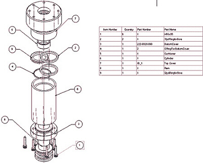
Exploded BOM drawings is where I have been clasically taught where this info should go (example attached). With Solidworks model it should be easy to generate some once model is confirmed "good copy". Then you can put heaps of information into drawing etc.
Another question though. Got all the drive/idler bars cut up and installed in laser cut frame, but in your assembly instructions it says to "Drill two 1/16" holes in the 5/16" x 230mm rods. (NNmm from one end and NNmm from the other end)".
Any idea what the NN numbers are?
> I should put this info somewhere but I am not sure
> where?
Exploded BOM drawings is where I have been clasically taught where this info should go (example attached). With Solidworks model it should be easy to generate some once model is confirmed "good copy". Then you can put heaps of information into drawing etc.
Another question though. Got all the drive/idler bars cut up and installed in laser cut frame, but in your assembly instructions it says to "Drill two 1/16" holes in the 5/16" x 230mm rods. (NNmm from one end and NNmm from the other end)".
Any idea what the NN numbers are?
|
Re: Solidworks Metric Assembly July 12, 2012 04:38AM |
Registered: 13 years ago Posts: 2,947 |
OK I have added a drill guide for the bars to the Drawings folder of the Tantillus git hub repo.
Thanks for doing all this work I am sure there will be many people that are happy to have a choice to the Blender files.
Thanks for doing all this work I am sure there will be many people that are happy to have a choice to the Blender files.
| FFF Settings Calculator | Gcode post processors | Geometric Object Deposition Tool Blog |
| Tantillus.org | Mini Printable Lathe | How NOT to install a Pololu driver |
|
Re: Solidworks Metric Assembly July 16, 2012 05:35AM |
Registered: 11 years ago Posts: 111 |
Sublime Wrote:
> Thanks for doing all this work I am sure there
> will be many people that are happy to have a
> choice to the Blender files.
No problem mate, got give something back for ecentially copying your years of work....
Anyhow progress:
CAD model has everything except a few bits of the electronics, and the gears. I have even put springs and drive wires into it. (Thanks Eric for the files). I will post up as seperate fork on github, so the masses may check it. No promises it is correct though till I have it assembled and running in the non-CAD realm.
Most parts printed, all parts cut. Hot end turned up, waiting on electronics.
Got the gantry part of it dry assembled. Ran into a few problems/points:
1. 8mm Hardend chromed bearing shaft was bent (50-100µm over 230mm) so bent it back to 10-20µm over 230mm. Leason learnt go pick up the shafting rather than having it couriered to you........
2. Got hardend chromed bearing shaft instead of what you reffer to as drill rod (which I believe is what we call centreless ground silver steel). Basically means I will have to homebrew EDM holes in shaft rather than drilling them. (Luckly a mate has made a howbrew sparker).
3. I cheated and used simplicity bushes instead of the printed ones. Basically because I had them lying around and they where only 1mm bigger in OD.
4. Could not get LM8SUU easily from the bearing shop quickly/cheaply, so I replaced them (and LM8UU) with LM8LUU. They over hang a little bit, but it will work for now.
5. I cheated again and got a 5mm to 6mm universal coupler for the Z-axis. It was only $8USD so I could not resist.
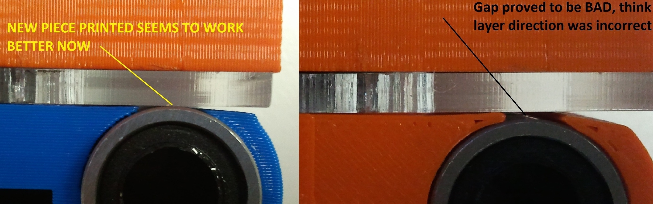
6. The upper half of the carriage seems to have not printed dimesionally correctly, so bearing shafts do not seems to line up correctly with ends. Probably 0.1mm to 0.25mm off. I think I got the layer direction wrong. I will take some photo's and post.
Thing I am stuck on at the moment is what to use for Z axis screw. Is it better to use high-tensile steel threaded rod or 316 Stainless steel rod? Also any thoughts on material selection for z-axis nuts. I am assuming Stainless on stainless is a bad idea.......
> Thanks for doing all this work I am sure there
> will be many people that are happy to have a
> choice to the Blender files.
No problem mate, got give something back for ecentially copying your years of work....
Anyhow progress:
CAD model has everything except a few bits of the electronics, and the gears. I have even put springs and drive wires into it. (Thanks Eric for the files). I will post up as seperate fork on github, so the masses may check it. No promises it is correct though till I have it assembled and running in the non-CAD realm.
Most parts printed, all parts cut. Hot end turned up, waiting on electronics.
Got the gantry part of it dry assembled. Ran into a few problems/points:
1. 8mm Hardend chromed bearing shaft was bent (50-100µm over 230mm) so bent it back to 10-20µm over 230mm. Leason learnt go pick up the shafting rather than having it couriered to you........
2. Got hardend chromed bearing shaft instead of what you reffer to as drill rod (which I believe is what we call centreless ground silver steel). Basically means I will have to homebrew EDM holes in shaft rather than drilling them. (Luckly a mate has made a howbrew sparker).
3. I cheated and used simplicity bushes instead of the printed ones. Basically because I had them lying around and they where only 1mm bigger in OD.
4. Could not get LM8SUU easily from the bearing shop quickly/cheaply, so I replaced them (and LM8UU) with LM8LUU. They over hang a little bit, but it will work for now.
5. I cheated again and got a 5mm to 6mm universal coupler for the Z-axis. It was only $8USD so I could not resist.
6. The upper half of the carriage seems to have not printed dimesionally correctly, so bearing shafts do not seems to line up correctly with ends. Probably 0.1mm to 0.25mm off. I think I got the layer direction wrong. I will take some photo's and post.
Thing I am stuck on at the moment is what to use for Z axis screw. Is it better to use high-tensile steel threaded rod or 316 Stainless steel rod? Also any thoughts on material selection for z-axis nuts. I am assuming Stainless on stainless is a bad idea.......
|
Re: Solidworks Metric Assembly July 16, 2012 02:56PM |
Registered: 13 years ago Posts: 2,947 |
willworkforplastic Wrote:
-------------------------------------------------------
> Got the gantry part of it dry assembled. Ran into
> a few problems/points:
>
> 1. 8mm Hardend chromed bearing shaft was bent
> (50-100µm over 230mm) so bent it back to 10-20µm
> over 230mm. Leason learnt go pick up the shafting
> rather than having it couriered to you........
My very first prototype had bend shafts and it did not effect the quality of the prints much at all (if any).
>
> 2. Got hardend chromed bearing shaft instead of
> what you reffer to as drill rod (which I believe
> is what we call centreless ground silver steel).
> Basically means I will have to homebrew EDM holes
> in shaft rather than drilling them. (Luckly a mate
> has made a howbrew sparker).
Drill rod is simply precision ground hardened steel rod. I did drill all the holes using a drill press and good drill bits.
>
> 3. I cheated and used simplicity bushes instead of
> the printed ones. Basically because I had them
> lying around and they where only 1mm bigger in
> OD.
I have a prusa with bronze bushings and they work nice but do wear out and can be a pain to change. I also have a Tantillus with the same style bushings as those but made out of Iglide material from Igus.
>
> 4. Could not get LM8SUU easily from the bearing
> shop quickly/cheaply, so I replaced them (and
> LM8UU) with LM8LUU. They over hang a little bit,
> but it will work for now.
It will reduce your build area by the amount they stick out but other than that they should work well. Also taking the machine apart once the cables are attached is almost impossible without removing the cables, so changing those after is not easy.
>
> 5. I cheated again and got a 5mm to 6mm universal
> coupler for the Z-axis. It was only $8USD so I
> could not resist.
I thought about using something like that but found the printed one worked really well for me. If it is really tall it could effect your max build height.
>
> 6. The upper half of the carriage seems to have
> not printed dimesionally correctly, so bearing
> shafts do not seems to line up correctly with
> ends. Probably 0.1mm to 0.25mm off. I think I got
> the layer direction wrong. I will take some
> photo's and post.
If you are referring to the height of the bars it looks like you may have made the bearing holes to high/low (when installed). I have the bearings protruding from the carriage parts so the acrylic presses against the bearing and helps to hold them in place.
>
> Thing I am stuck on at the moment is what to use
> for Z axis screw. Is it better to use high-tensile
> steel threaded rod or 316 Stainless steel rod?
> Also any thoughts on material selection for z-axis
> nuts. I am assuming Stainless on stainless is a
> bad idea.......
I have tried both steel and stainless and I have to say that it is hands down stainless. It takes threads better apparently and this shows in the layer alignment. I have one machine out of all of mine that has steel and it does not print nearly as nice as the rest.
| FFF Settings Calculator | Gcode post processors | Geometric Object Deposition Tool Blog |
| Tantillus.org | Mini Printable Lathe | How NOT to install a Pololu driver |
|
Re: Solidworks Metric Assembly July 18, 2012 05:28AM |
Registered: 11 years ago Posts: 111 |
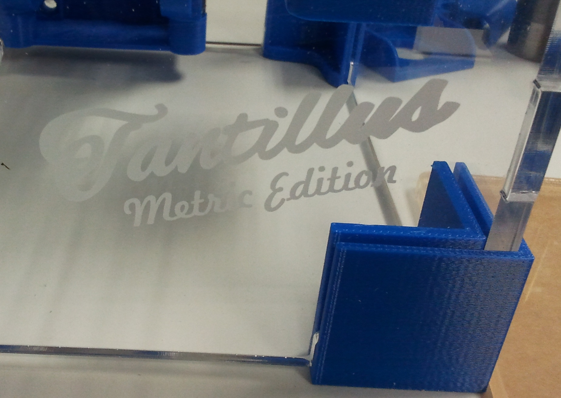
Yup, upper carriage printed incorrectly, think I got the layer direction incorrect. Changed layer direction and this helped heaps. See attached photo, if you are interested.
If you can drill the shaft with HSS drill bits then it is probably not in a fully hardened state. Bit of a fail on my behalf for getting chromed, case hardened bearing shaft. Home brew EDM will save the day though.....
A side point, interestingly enough a while back on a work project, my bearing supplier told me I could not use centreless ground silver steel shaft (drill shaft) as bearing shaft for linear ball bushes or simplicity bushes. A collegue wanted to use it so we could thread easily as it is not in a fully hardened state like the bearing shaft. The supplier reasoning was that the surface roughness is too high on the silver steel and would essentially be a rough surface compared to bearing shaft causing pre-mature bearing/bush failures etc. We used silver steel anyhow with linear ball bushes and it is still working fine.
Anyhow progress is hinged now on stepper motors (42BYGHW609 I am assuming are the ones to get) which reprap discount is out of stock off, .
.
At any rate I will get SW model up onto Github for others to check over, I am sure there will be more mistakes in it...........
If you can drill the shaft with HSS drill bits then it is probably not in a fully hardened state. Bit of a fail on my behalf for getting chromed, case hardened bearing shaft. Home brew EDM will save the day though.....
A side point, interestingly enough a while back on a work project, my bearing supplier told me I could not use centreless ground silver steel shaft (drill shaft) as bearing shaft for linear ball bushes or simplicity bushes. A collegue wanted to use it so we could thread easily as it is not in a fully hardened state like the bearing shaft. The supplier reasoning was that the surface roughness is too high on the silver steel and would essentially be a rough surface compared to bearing shaft causing pre-mature bearing/bush failures etc. We used silver steel anyhow with linear ball bushes and it is still working fine.
Anyhow progress is hinged now on stepper motors (42BYGHW609 I am assuming are the ones to get) which reprap discount is out of stock off,
. At any rate I will get SW model up onto Github for others to check over, I am sure there will be more mistakes in it...........
|
Re: Solidworks Metric Assembly July 18, 2012 06:03AM |
Registered: 13 years ago Posts: 2,947 |
willworkforplastic Wrote:
-------------------------------------------------------
> Yup, upper carriage printed incorrectly, think I
> got the layer direction incorrect. Changed layer
> direction and this helped heaps. See attached
> photo, if you are interested.
Strange as the way you first printed it is the way I intended. I use slic3r and it does not print the very tip of those because they are to narrow. What slicer are you using (skeinforge) it may be printing the tips even though the path is wider than the tip.
>
> A side point, interestingly enough a while back on
> a work project, my bearing supplier told me I
> could not use centreless ground silver steel shaft
> (drill shaft) as bearing shaft for linear ball
> bushes or simplicity bushes. A collegue wanted to
> use it so we could thread easily as it is not in a
> fully hardened state like the bearing shaft. The
> supplier reasoning was that the surface roughness
> is too high on the silver steel and would
> essentially be a rough surface compared to bearing
> shaft causing pre-mature bearing/bush failures
> etc. We used silver steel anyhow with linear ball
> bushes and it is still working fine.
I believe I have read on some bushings that the shaft must not be polished.
>
> Anyhow progress is hinged now on stepper motors
> (42BYGHW609 I am assuming are the ones to get)
> which reprap discount is out of stock off,.
They are sold by many people. Google the number and you will find a lot of sources. Even eBay. They are made by a company called Wantai motor and sold by places like Phidgets under their name but Wantai's part number.
-------------------------------------------------------
> Yup, upper carriage printed incorrectly, think I
> got the layer direction incorrect. Changed layer
> direction and this helped heaps. See attached
> photo, if you are interested.
Strange as the way you first printed it is the way I intended. I use slic3r and it does not print the very tip of those because they are to narrow. What slicer are you using (skeinforge) it may be printing the tips even though the path is wider than the tip.
>
> A side point, interestingly enough a while back on
> a work project, my bearing supplier told me I
> could not use centreless ground silver steel shaft
> (drill shaft) as bearing shaft for linear ball
> bushes or simplicity bushes. A collegue wanted to
> use it so we could thread easily as it is not in a
> fully hardened state like the bearing shaft. The
> supplier reasoning was that the surface roughness
> is too high on the silver steel and would
> essentially be a rough surface compared to bearing
> shaft causing pre-mature bearing/bush failures
> etc. We used silver steel anyhow with linear ball
> bushes and it is still working fine.
I believe I have read on some bushings that the shaft must not be polished.
>
> Anyhow progress is hinged now on stepper motors
> (42BYGHW609 I am assuming are the ones to get)
> which reprap discount is out of stock off,
. They are sold by many people. Google the number and you will find a lot of sources. Even eBay. They are made by a company called Wantai motor and sold by places like Phidgets under their name but Wantai's part number.
| FFF Settings Calculator | Gcode post processors | Geometric Object Deposition Tool Blog |
| Tantillus.org | Mini Printable Lathe | How NOT to install a Pololu driver |
|
Re: Solidworks Metric Assembly July 18, 2012 06:29AM |
Registered: 11 years ago Posts: 111 |
It is done, I think hopefully I have forked from main project on github and uploaded to download area:
Pack and Go of Solidworks Model (Eric Can you check it opens OK for me?)
Parasolid of Model, for people with different CAD packages or Earlier SW versions
Edrawing so people can download free viewer from [www.edrawingsviewer.com] and then have 3d cad model they can rotate/isolate parts in etc.
For those of you downloading, remember no one has built a working Tantillus of this model, so it WILL no doubt have some error's in it.............. If you find any tell me and I will sort out.

Sorry, only registered users may post in this forum.