Solidworks Metric Assembly
Posted by willworkforplastic
|
Re: Solidworks Metric Assembly July 18, 2012 02:53PM |
Registered: 11 years ago Posts: 149 |

|
Re: Solidworks Metric Assembly July 18, 2012 03:18PM |
Registered: 13 years ago Posts: 2,947 |
I couldn't figure out where you had put them and had to re-read a few times to get the part about the downloads area.
You should have a look through this [help.github.com] that way others can fork and contribute to the project. It will also let me "pull" parts of it to my repo when they are ready.
You should have a look through this [help.github.com] that way others can fork and contribute to the project. It will also let me "pull" parts of it to my repo when they are ready.
| FFF Settings Calculator | Gcode post processors | Geometric Object Deposition Tool Blog |
| Tantillus.org | Mini Printable Lathe | How NOT to install a Pololu driver |
|
Re: Solidworks Metric Assembly July 20, 2012 03:10PM |
Registered: 11 years ago Posts: 95 |
I've downloaded the SW assy. Thanks so much for making this. It's really helped me to understand the bits and pieces of where things go, and how the parts relate. It certainly will be of great help to reference when assembling Tantillus.
BTW - The assy didn't seem to have gears in it in either the .x_t or the .sldasm - is this correct, or did I lose something to the interwebs?
I've already made a nurbs version of the 66mm gear. But I noticed the blender files had an assortment of gears. I'm still unclear on which gears are to be used. I'll have another look as I've not yet really given it much energy.
thanks again!
Edited 1 time(s). Last edit at 07/20/2012 03:32PM by ernchesto.
|
Re: Solidworks Metric Assembly July 20, 2012 06:22PM |
Registered: 13 years ago Posts: 2,947 |
ernchesto Wrote:
-------------------------------------------------------
> I've already made a nurbs version of the 66mm
> gear. But I noticed the blender files had an
> assortment of gears. I'm still unclear on which
> gears are to be used. I'll have another look as
> I've not yet really given it much energy.
It uses the large herringbone gears with the hex hole on the upper shafts for X and Y.
It uses the large herringbone gears with the 4 or 5mm hole on the motors for X and Y.
The small gears are for the extruder. The herringbone gears (3.3:1) are difficult to print and may wear out prematurely (still using my first set). I recommend using the other ones (2.7:1) they are stronger and allow for faster retracts.
The Reason the blend files are littered with gears is because I import them back in to repair the stl's before final export. It also allows me to move them around and render them without the lag of doing the boolean functions and modifiers.
Edited 1 time(s). Last edit at 07/20/2012 07:10PM by Sublime.
| FFF Settings Calculator | Gcode post processors | Geometric Object Deposition Tool Blog |
| Tantillus.org | Mini Printable Lathe | How NOT to install a Pololu driver |
|
Re: Solidworks Metric Assembly July 21, 2012 01:21AM |
Registered: 11 years ago Posts: 95 |
"It uses the large herringbone gears with the hex hole on the upper shafts for X and Y.
It uses the large herringbone gears with the 4 or 5mm hole on the motors for X and Y."
Ah, I see - I only made the XY gear that didn't have the hex in it, and was wondering what was up with the centre hole being too small for the upper shafts. Silly me.
"The small gears are for the extruder. The herringbone gears (3.3:1) are difficult to print and may wear out prematurely (still using my first set). I recommend using the other ones (2.7:1) they are stronger and allow for faster retracts."
Good to know, thanks.
"The Reason the blend files are littered with gears is because I import them back in to repair the stl's before final export. It also allows me to move them around and render them without the lag of doing the boolean functions and modifiers."
No need to explain. I'm floored at the fact that you made this in Blender with such short self-training (if I'm not mistaken). I'm consistently impressed with people's output from Blender. I've had a few goes, but I suppose my noodle has been 'trained' to think in a different way. I actually think it makes it harder to learn...Anyway, I'm enjoying roaming through your 3D thoughts in the model, and the nurbs model is just nicer for me to navigate.
Cheers!
|
Re: Solidworks Metric Assembly July 24, 2012 06:30AM |
Registered: 11 years ago Posts: 111 |
Sorry Chaps been off the grid, house reno's have been sucking up my time (and a bit of paintball). Builder put a dry wall screw through a gas pipe, nothing like waking up to the smell of gas in the morning, sigh............
Anyhow:
On the carriage printing issue:
I am using dimension's catylst software to do the STL file processing. You get about three options = sux. Have to as that is all the uprint plus FDM machine will operate on. Just another reason their system pisses me off, dam them for having the patent on heated enviroments while building. I swear one of these days I am going to rip there controller out and replace it with a ramps...... Why do the commerical systems always sux.........
However good reason someone should try to print the SW model off a tantillus machine, just to make sure it comes out right. I have about a quee of 5 people already at work who want a tantillus so I will try once I have my machine going.
On the stepper motor supply issue:
I'll just wait for reprap discount. Figure best to support them since their prices are good. They just sent me a full wiring kit which seemed to be good quality, and the electronics. Free Fedex shipping as well!
The github forking issue:
My bad, I forked the project, but did not install the windows client to commit through changes, instead I put them in the download area. Sorry I am a noob when it comes to all things programing related. Last time I tapped away at code was 10 years ago at Univeristy. Anyhow hopefully I have pushed through a commit now so hopefully you can see it sublime and pull the files. Fingers crossed. Tell me once it is all good and I will delete the files from the download area.
The gears not being in the SW model:
I have not yet put them in as I have not modelled them (time issue). I was temped to just put the STL's in as surface bodies but it seems to really slow the model down. Even on my I5-2500K OC 4.5GHz machine. So I opted not to as I guessed not most people will be running extreme hardware.
Anyhow good to here the model opened for you eric. Dam I was worried it wouldn't or pull in massive fastners from the tool box in typical SW fashion.
And I too second erichesto comment on sublime: "I'm floored at the fact that you made this in Blender".
Anyhow that is enough ranting for now.
|
Re: Solidworks Metric Assembly August 06, 2012 05:57AM |
Registered: 11 years ago Posts: 111 |
|
Re: Solidworks Metric Assembly August 06, 2012 06:40AM |
Registered: 13 years ago Posts: 2,947 |
willworkforplastic Wrote:
-------------------------------------------------------
> Hey Sublime,
>
> Did I manage to fork the repo and comit the Solid
> works files correctly?
Fork properly? Yes
Commit properly? No it does not look like it has been pushed through. [github.com] shows me as the last commit.
Did you "git push origin master" ?
>
> Also where would I find wiring diagram for LCD and
> encoder?
I am wiring them like Panel Max and/or the Ultipanel are wired except I use different pins (see pins.h file RAMPS pinout). For a tutorial on how to wire Panel max see [tommyc-reprap.blogspot.ca] . Just remember Tantillus uses a 16x2 LCD not a 10x4 (same pinout). I also use a potentiometer to set the brightness and contrast as opposed to the resistor.
>
> Yes I am getting close!!!
Looks like you may be the first to complete their machine.
| FFF Settings Calculator | Gcode post processors | Geometric Object Deposition Tool Blog |
| Tantillus.org | Mini Printable Lathe | How NOT to install a Pololu driver |
|
Re: Solidworks Metric Assembly August 14, 2012 05:29AM |
Registered: 11 years ago Posts: 111 |
There seems to be the smell of many partially complete tantillus in the air tonight, good work sublime. Soon they will just replicate themselves. Hmmm I think that might be warning bells...........
> Looks like you may be the first to complete their
> machine.
Nah I doubt it, gotta go offshore for a week, so no playing for a week. I was temped to pack it in my bag however.
However almost there, electronics fire up and all going now. Just got to sort out z-axis/stop and the extruder. Looks like I am going to have to replicate it 10 odd times for boys at work.
Which brings me to a question, is the tantillus designed to run 1.75mm fillment or 3mm fillment? Tried manually feeding 3mm through ID 4mm Nylon tube and that was a fail, so I am guessing it is 1.75mm.
> Did you "git push origin master" ?
Hmm I am using the windows client, once I have a working machine with new SW files I will try again, and read up on helps/try on a test case first.
As for those who wish to make the tantillus from the metric Solidworks files a few changes I will release once I have actually completed the machine:
1. XY ends had sizing for a imperial nut, changed now to metric sizing. Also had too much clearance on the 8mm shaft hole, 8.2mm reduced to 8.0mm (on size).
2. Fan mounts snap hocks, just snaped off, so had to reduce there height maybe because I am forced to use ABS at this stage.
3. Slight issue with top part of carriage not clamping hot end well. That is blind hole slightly too deep. Reduced clearance to on size and seems to work now.
4. Left massive features of extruder (woops) so no clearance for steper motor gear.
|
Re: Solidworks Metric Assembly August 14, 2012 06:35AM |
Registered: 13 years ago Posts: 2,947 |
willworkforplastic Wrote:
-------------------------------------------------------
> There seems to be the smell of many partially
> complete tantillus in the air tonight, good work
> sublime. Soon they will just replicate themselves.
> Hmmm I think that might be warning
> bells...........
The pink one in my new build instruction pictures is the only Tantillus printed entirely on another Tantillus (printed on the original printed Tantillus) so far.
> Which brings me to a question, is the tantillus
> designed to run 1.75mm fillment or 3mm fillment?
> Tried manually feeding 3mm through ID 4mm Nylon
> tube and that was a fail, so I am guessing it is
> 1.75mm.
It uses 3mm filament in 1/4"od x 1/8"id PTFE tubing and the original prototypes used 1/4"od x 5/32"id (4mm) Nylon air brake tubing. I do not like the idea of pushing 1.75mm filament down a tube. To convert it to 1.75 you would have to have a hobbed bolt with shallow hobbing or move the filament hole in the extruder. You would also need 2mm id PTFE tubing.
>
> As for those who wish to make the tantillus from
> the metric Solidworks files a few changes I will
> release once I have actually completed the
> machine:
>
> 1. XY ends had sizing for a imperial nut, changed
> now to metric sizing. Also had too much clearance
> on the 8mm shaft hole, 8.2mm reduced to 8.0mm (on
> size).
Yeah the 8.2 was for printing on most DIY machines.
> 2. Fan mounts snap hocks, just snaped off, so had
> to reduce there height maybe because I am forced
> to use ABS at this stage.
I just added a video that shows how to install the fans without breaking them. It is in the electronics section of Tantillus.org build guide.
> 4. Left massive features of extruder (woops) so no
> clearance for steper motor gear.
The extruder is a complicated part that has a lot of small subtle features.
| FFF Settings Calculator | Gcode post processors | Geometric Object Deposition Tool Blog |
| Tantillus.org | Mini Printable Lathe | How NOT to install a Pololu driver |
|
Re: Solidworks Metric Assembly August 15, 2012 07:22AM |
Registered: 13 years ago Posts: 2,947 |
Looks like you have figured out Github. Or at least you managed to upload the Metric source 8 days ago.
| FFF Settings Calculator | Gcode post processors | Geometric Object Deposition Tool Blog |
| Tantillus.org | Mini Printable Lathe | How NOT to install a Pololu driver |
|
Re: Solidworks Metric Assembly August 18, 2012 05:38PM |
Registered: 11 years ago Posts: 111 |
> Looks like you have figured out Github. Or at
> least you managed to upload the Metric source 8
> days ago.
Yeah I think I forgot to push the sync button on the windows client. F'ed it up though because I think i committed then reverted then reverted the revert. Sigh. Next rev, hopefully I'll get it right, fingers crossed. I might do some exploded BOM drawings as well, just to help the masses.
As for filament size I'll stick to what you use. I think my issues spawn from the nylon tube and the fact my 3mm sample PLA is very rough on its surface. From memory I can get PTFE tube from hydraulic suppliers so I will give that a try. It maybe the one thing I have to get in imperial .
.
Fan mounts I actually did install them like your video, I think the issue was I got dimensions lost in translation again. I will double check and correct if need be.
Just to pick your brain some more if you do not mind sublime, on hobbed bolts is there a good way you have found to make them. I was just going to use a M3/M4 spiral tap/mill/free spinning stainless bolt to make. However I see people use large pitches, like M5 and what looks to be M8. Or is it better to straight cut the teeth with a knurling tool on a lathe?
Build instructions are looking good on your website as well. Nice work.
> least you managed to upload the Metric source 8
> days ago.
Yeah I think I forgot to push the sync button on the windows client. F'ed it up though because I think i committed then reverted then reverted the revert. Sigh. Next rev, hopefully I'll get it right, fingers crossed. I might do some exploded BOM drawings as well, just to help the masses.
As for filament size I'll stick to what you use. I think my issues spawn from the nylon tube and the fact my 3mm sample PLA is very rough on its surface. From memory I can get PTFE tube from hydraulic suppliers so I will give that a try. It maybe the one thing I have to get in imperial
.Fan mounts I actually did install them like your video, I think the issue was I got dimensions lost in translation again. I will double check and correct if need be.
Just to pick your brain some more if you do not mind sublime, on hobbed bolts is there a good way you have found to make them. I was just going to use a M3/M4 spiral tap/mill/free spinning stainless bolt to make. However I see people use large pitches, like M5 and what looks to be M8. Or is it better to straight cut the teeth with a knurling tool on a lathe?
Build instructions are looking good on your website as well. Nice work.
|
Re: Solidworks Metric Assembly August 18, 2012 10:45PM |
Registered: 13 years ago Posts: 2,947 |
willworkforplastic Wrote:
-------------------------------------------------------
> Just to pick your brain some more if you do not
> mind sublime, on hobbed bolts is there a good way
> you have found to make them. I was just going to
> use a M3/M4 spiral tap/mill/free spinning
> stainless bolt to make. However I see people use
> large pitches, like M5 and what looks to be M8. Or
> is it better to straight cut the teeth with a
> knurling tool on a lathe?
I use an #8-32 three fluted tap in a drill press with the bolt in two bearing blocks. It can not use a straight cut hobbed bolt or knurled one because the hobbing has to be a certain depth to line up with the filament hole and Bowden tube entrance. It also increases torque.
| FFF Settings Calculator | Gcode post processors | Geometric Object Deposition Tool Blog |
| Tantillus.org | Mini Printable Lathe | How NOT to install a Pololu driver |
|
Re: Solidworks Metric Assembly September 02, 2012 05:28AM |
Registered: 11 years ago Posts: 111 |
ITS ALIVE, ITS ALIVE!
And john connor did not come knocking at my door, so no AI self-replicating worries, fingers crossed.
Hmm I wounder how many more movie refferences I can put into this post?
So after a few (ok maybe 10) PLA 20mm test cubes it seems to be working well (off by about 0.5mm with no real attempt at calibration). Last thing to do is put another 50mm fan on it, and it will be complete. Simplicity bushes seem to be going well, but time will tell how they go.
Loving the 0.1mm layer resolution, reminds me of comerical SLA not silly comericial we can only do 0.254mm layer resolution expensive FDM.
Anyhow a note for you metric fends if you use 6mm threaded rod on the z-axis, go into the firmware, find confguration.h, line 178 change 2514.628 to 3200, for the steps per unit.
However sublime I have a few more questions (sorry I have tried to figure these out on my own, but I need some professional advise):
1. My first prints the last layer appeared to have micro-holes in it. I assume this is because there is not enough flow coming out the nozzle, because I hobbed my own bolt with a M4 tap, probably not to the correct depth as well. Anyhow in configuration.h, line 178 I changed extruder steps per unit to 450. Now it seems to be OK. Is this the correct way of thinking?
2. The corners of the cube on the glass plate bow upwards. Is this because I am using Cap-teh-ton (kapton) tape and not the blue masking tape? I only had kapton tape lying around.
3. Dam those pololu drivers run hot I cannot touch the small heatsink on them (I realize they can but just doesn't feel right to me). I am running the refference voltage at around 0.2V on them so I assume that is only 0.2 X 2.5 = 0.5A on the steppers (running 19V supply). Any higher and I can hear the thermal shut down on the PWM noise occuring. Does that sound right, I would have thought running them at about 1A should be about normal considering the steppers are 1.7A coils? I might do some custom heatsinks anyhow on my CNC.
4. I get this werid flashing on the corner of the cube where the nozzle starts its layer, half way up the cube. Any thoughts to why?
Photo's attached to aid my points.
Anyhow, I'll get onto the drawings (BOM/assembly notes etc) and tidying up the model. Drawings should help the masses with assembly etc. Then next is heated bed (want to try abs) and then polycarbonate, but I relize I will probably have to make a macor (machinable ceramic) hot end.
I'm so excited and I just cant hide it...........
3 moive refferences ah ha haha.
Or wait is that 4?
|
Re: Solidworks Metric Assembly September 02, 2012 03:08PM |
Registered: 13 years ago Posts: 2,947 |
willworkforplastic Wrote:
-------------------------------------------------------
> Anyhow a note for you metric fends if you use 6mm
> threaded rod on the z-axis, go into the firmware,
> find confguration.h, line 178 change 2514.628 to
> 3200, for the steps per unit.
I will add a note in the firmware that says something to the effect of "If using m6 threaded rod for Z the steps per mm are 3200"
> 1. My first prints the last layer appeared to
> have micro-holes in it. I assume this is because
> there is not enough flow coming out the nozzle,
> because I hobbed my own bolt with a M4 tap,
> probably not to the correct depth as well. Anyhow
> in configuration.h, line 178 I changed extruder
> steps per unit to 450. Now it seems to be OK. Is
> this the correct way of thinking?
Yes this is exactly how I do it. I have written a small tutorial on calibrating a few parts [www.tantillus.org] Once it is complete I will reorganize the site so it flows form the assembly to the calibration.
>
> 2. The corners of the cube on the glass plate bow
> upwards. Is this because I am using Cap-teh-ton
> (kapton) tape and not the blue masking tape? I
> only had kapton tape lying around.
As far as I know you need a heated bed when using Kapton tape. For cold printing the Blue Tape is the best option.
>
> 3. Dam those pololu drivers run hot I cannot touch
> the small heatsink on them (I realize they can but
> just doesn't feel right to me). I am running the
> refference voltage at around 0.2V on them so I
> assume that is only 0.2 X 2.5 = 0.5A on the
> steppers (running 19V supply). Any higher and I
> can hear the thermal shut down on the PWM noise
> occuring. Does that sound right, I would have
> thought running them at about 1A should be about
> normal considering the steppers are 1.7A coils? I
> might do some custom heatsinks anyhow on my CNC.
This depends on who's driver you are using. If you are using real pololu's you can use the reference voltage to set it up. But if you are using RepRapDiscounts drivers you need to set it much lower since the two reference resistors are 000 links. I personally adjust them without the multimeter and just start low and turn them up until the axis move and it does not go into thermal protection. Then I adjust them just a tiny bit until the annoying squeal goes away.
But yes they do run really hot and can burn you before they get damaged.
> 4. I get this werid flashing on the corner of the
> cube where the nozzle starts its layer, half way
> up the cube. Any thoughts to why?
Because your E-steps per mm is set higher there is a good chance you need to reduce your maximum E speed. Marlin does this funny thing where if the max speed is set higher then the max step rate the firmware is capable of (result of having the retract acceleration set to the max) it defaults the retract to a slow speed. For 450 steps it would be some where around 45mm/s max E speed (line 179 of the config file). I have a tutorial half made for this and will try and get it up soon.
It may also be from having the E steps per mm set to high and the excess material is oozing out at the retract / Z change location.
It may also be result of the new lead screws step count making the max Z speed to high and Marlin does not like it so it is ending up going really slow. Try using pronterface to move Z 50mm at say 12,000mm/m and see if it works. If it stalls or does something weird then the max is too high and it can not do it.
Also are you using Slic3r 0.7.2 with my configs? It has some strange settings like the retract is set at 1000mm/s to ensure it always retracts at full speed regardless of lowering the print speed via the LCD. The path widths are manually set to work with a bowden cable correctly, etc, etc. All of these things go against normal RepRap convention and contradict what others will tell you on the forum because they are used to direct mounted extruders. Oh and the default setting that come with Slic3r will result in very poor prints from Tantillus.
> Anyhow, I'll get onto the drawings (BOM/assembly
> notes etc) and tidying up the model. Drawings
> should help the masses with assembly etc. Then
> next is heated bed (want to try abs) and then
> polycarbonate, but I relize I will probably have
> to make a macor (machinable ceramic) hot end.
RichRap printed PC with a peek based hotend and some extra cooling on the peek without any problems other than the ones associated with trying to get PC to print as well as PLA or ABS. For ABS you can print small items without the heated bed or even larger parts by printing on acrylic (may not come off the acrylic if the first layer was too low). I would suggest a Peltier module for the heated bed so it cools the Z-arms while heating the bed. It will also help keep the electronics cool at the bottom of the case.
Excellent work on the re-design. Can you push another commit to Github so the rest of us can play with your model / drawings.
| FFF Settings Calculator | Gcode post processors | Geometric Object Deposition Tool Blog |
| Tantillus.org | Mini Printable Lathe | How NOT to install a Pololu driver |
|
Re: Solidworks Metric Assembly September 05, 2012 07:37AM |
Registered: 11 years ago Posts: 111 |
Thanks for calibration info I will have a crack at it this weekend. Bugger about the Asian Pololu's but such is. I tried some cheap asia blue masking tape as well with no luck so I will have to hunt for the 3M scotch stuff.
I will get on the drawings/model but bear with me my computer is giving me hell, so time for a rebuild.
As for peltiers as a heated bed, they are a good idea (love the idea of using cool air for cooling things and aluminium can be used to spread heat well) but they come at a trade off. Complexity is an issue (need to really spring load them up as they crack with thermal expansion), they really can only run up to 80oC, and they are inefficient at cooling (lucky this does not matter for us). The cheap ones have a habbit of craping out as well. I know this all too well as I built a 600W (cooling power) rig about 6 months ago. Worked well however in the end.
For now I might just have a crack at nichrome wiring a piece of 6mm glass and coating with dymax 9-20801. That should be able to do at a stretch up to 150oC. Maybe some cermic standoff's as well .Not easily copied if people do not have access to dymax products though. Failing that hacking a heated bed MK2 with conductive silver and then gluing to a piece of glass may also work. Then once I have printed off about 10 sets of tantillus parts for people I can look at doing it with peltiers.
I will get on the drawings/model but bear with me my computer is giving me hell, so time for a rebuild
.As for peltiers as a heated bed, they are a good idea (love the idea of using cool air for cooling things and aluminium can be used to spread heat well) but they come at a trade off. Complexity is an issue (need to really spring load them up as they crack with thermal expansion), they really can only run up to 80oC, and they are inefficient at cooling (lucky this does not matter for us). The cheap ones have a habbit of craping out as well. I know this all too well as I built a 600W (cooling power) rig about 6 months ago. Worked well however in the end.
For now I might just have a crack at nichrome wiring a piece of 6mm glass and coating with dymax 9-20801. That should be able to do at a stretch up to 150oC. Maybe some cermic standoff's as well .Not easily copied if people do not have access to dymax products though. Failing that hacking a heated bed MK2 with conductive silver and then gluing to a piece of glass may also work. Then once I have printed off about 10 sets of tantillus parts for people I can look at doing it with peltiers.
|
Re: Solidworks Metric Assembly September 23, 2012 04:59AM |
Registered: 11 years ago Posts: 111 |
"Good New Everybody!"
I have managed to get the latest SW model up on Github and it looks like I have done it properly now!
Big ups to eric for the involuted gear/electronics models as well, the assembly is looking pretty sweet now. The only thing is I think I have the plattern design wrong. If someone can tell me the dim's of the glass and the acrylic platters I will correct. I could not find them in the original dxf's.
And please if anything is wrong just tell me.
It should be pretty easy as well to mod/hack the assembly to whatever with the configs/design tables under parts etc.
I have not got onto the drawings yet, but they should hopefully come in the coming week.
However master-san (sublime) I am struggling to get epic prints out of my Tantillus.
This is what I have done since my last post:
1. Moved the Z axis up and down 5 times, by putting pronterface Z speed up to 12,000. One 10mm move and it made a funny noise. So I put the Default Max Feed rate (Configuration line 179) from 15 to 12. Repeated moves and did not happen again.
2. Correct my PEBCAK error. Turns out I had down loaded latest version of slicer and not 0.7.2. Feel like a moron............
3. The X/Y axis gears where out of square by 0.7mm when I clocked them. Basically caused blacklash in one portion of the gear mesh and interference in another. Looks like I drilled them out wrong/M8 nut is to big for them. So I have managed to get this down to 0.2mm, which seems to be OK, but now I have proper CAD models I should be able to get this down to 0.05mm as I can change the clearance in the gear for a M8 nut. See attached photo to see where I clocked them.
4. Got better material, sample stuff I had was crap because of surface finish and water content. It was slipping in extruder and guming up the hobbed bolt.
5. Calibrated head to bed distance as per your tutorial. All good there. Do you know what the actual target distance is? I am thinking about making a proper feeler gauge up for it. As I never seem to have paper when I need it, typical.......
5. Calibrated material flow as per your tutorial. Now got a better number of 345. See attached photo of last layer of your calibration cube, just to be sure I am judging it correctly.
6. Printed your calibration pyramid. Wound the extruder speed slowly up to 55, did not see the slow down so figured that is what it should be.
However have a look at the attached photo's of the completed pyramid. It does not look right to me. It is like the retract distance is not enough and the circles are not coming out right. Should I up the retract distance, and is the jerk values a place to compensate for gear backlash? Any of your master 3d printing thoughts would be most appreciated anyhow in your own time.
|
Re: Solidworks Metric Assembly September 23, 2012 06:51AM |
Registered: 13 years ago Posts: 2,947 |
willworkforplastic Wrote:
-------------------------------------------------------
> "Good New Everybody!"
> I have managed to get the latest SW model up on
> Github and it looks like I have done it properly
> now!
>
> Big ups to eric for the involuted gear/electronics
> models as well, the assembly is looking pretty
> sweet now. The only thing is I think I have the
> plattern design wrong. If someone can tell me the
> dim's of the glass and the acrylic platters I will
> correct. I could not find them in the original
> dxf's.
They are a result of the cutout of the windows and are part of All_panels.dxf
> 1. Moved the Z axis up and down 5 times, by
> putting pronterface Z speed up to 12,000. One 10mm
> move and it made a funny noise. So I put the
> Default Max Feed rate (Configuration line 179)
> from 15 to 12. Repeated moves and did not happen
> again.
This is most likely because m6 takes more steps per mm which limits the max speed. But could also just be you need to lubricate the threaded rod.
> 3. The X/Y axis gears where out of square by 0.7mm
> when I clocked them. Basically caused blacklash in
> one portion of the gear mesh and interference in
> another. Looks like I drilled them out wrong/M8
> nut is to big for them. So I have managed to get
> this down to 0.2mm, which seems to be OK, but now
> I have proper CAD models I should be able to get
> this down to 0.05mm as I can change the clearance
> in the gear for a M8 nut. See attached photo to
> see where I clocked them.
I haven't found that being out of square in that direction effects the print quality. But backlash in one place and binding in another definitely does cause issues.
> 5. Calibrated head to bed distance as per your
> tutorial. All good there. Do you know what the
> actual target distance is? I am thinking about
> making a proper feeler gauge up for it. As I never
> seem to have paper when I need it, typical.......
Technically we want zero and then the first layer code is 0.2mm. But that is hard to achieve via the endstop adjustment. So I have you get it close with the paper and because the nozzle is compressing the paper and blue tape you are really close to zero. Then you use Slic3r to set the Z offset and end up at true zero or below.
> 5. Calibrated material flow as per your tutorial.
> Now got a better number of 345. See attached photo
> of last layer of your calibration cube, just to be
> sure I am judging it correctly.
The outer perimeters look a little too far apart (spaces) which would indicate that the flow is a little low. Can you get a knife blade between the perimeters? You want all the paths to touch the one next to it and stick well to each other.
> 6. Printed your calibration pyramid. Wound the
> extruder speed slowly up to 55, did not see the
> slow down so figured that is what it should be.
You can try even faster. But if you increase the E-steps again you will find the max speed changes too. Also much faster you will find that it can eat the filament during rapid retraction and unretraction.
> However have a look at the attached photo's of the
> completed pyramid. It does not look right to me.
> It is like the retract distance is not enough and
> the circles are not coming out right. Should I up
> the retract distance, and is the jerk values a
> place to compensate for gear backlash? Any of your
> master 3d printing thoughts would be most
> appreciated anyhow in your own time.
Ok those types of strings are from ooze during travel. This says that either it is not retracting fast/far enough or it is too hot and the filament is almost liquid. Since you are retracting at 55mm/s and are using my configs (5mm or 5.5mm of retract) I would think it is the later and the filament you have melts at a lower temp. I have the print temperatures in the profiles set a little high to ensure it will melt any brand of PLA. Some PLA can be printed as low as 160c. My suggestion is to slice a calibration cube and and print it. Then lower the temp 5c and try again. Do this over and over until you get the temp low enough that it either stops extruding or the layers stop to stick to each other. Once you find that point increase the temp 10c and try the pyramid again with the new temperature. I would leave the first layer temp at 200c so it sticks well to the blue tape.
One last thing. The firmware has a setting to prevent extrusions below a certain temperature. It is currently set at 170c and if the nozzle goes below that it will stop the extruder from turning. You can easily lower it if you find your filament needs lower temps. You can also temporarily disable it with M302
The jerk setting sets the speed it will change direction based on the angel change. I am not sure how the math works and I have heard it is not actually a true "jerk" calculation so the number does not represent anything.
Edited 1 time(s). Last edit at 09/23/2012 07:03AM by Sublime.
| FFF Settings Calculator | Gcode post processors | Geometric Object Deposition Tool Blog |
| Tantillus.org | Mini Printable Lathe | How NOT to install a Pololu driver |
|
Re: Solidworks Metric Assembly September 23, 2012 11:17PM |
Registered: 13 years ago Posts: 2,947 |
Is it possible that someone could export the parts in an opensource format? I personally would be happy to have the entire model exported as one single STL. This way I can import it into Blender with all the parts in the correct orientation. Blender will split the model back into separate parts with ease. I know for others it would be nice to have all the parts exported like I have in the original repo in folders as Stl's ready for printing.
Edited 1 time(s). Last edit at 09/23/2012 11:29PM by Sublime.
Edited 1 time(s). Last edit at 09/23/2012 11:29PM by Sublime.
| FFF Settings Calculator | Gcode post processors | Geometric Object Deposition Tool Blog |
| Tantillus.org | Mini Printable Lathe | How NOT to install a Pololu driver |
|
Michal
Re: Solidworks Metric Assembly September 24, 2012 07:59AM |
|
Re: Solidworks Metric Assembly September 24, 2012 02:55PM |
Registered: 11 years ago Posts: 149 |
Tried to put the STL here:
[github.com]
I think it worked because I can download the STL, but I cannot open and check the STL myself because it crashes Solidworks. Also I had an error message when I pushed/uploaded the repo from my command line, but it looks to me like everything uploaded fine.
If you want each part by itself I can do that easily as well (it just takes a checkbox click - I don't have to save each part individually)
Edit: Not sure this is the proper thread, but the other night it occurred to me that using some mechanism similar to a guitar tuning peg might be handy if it could be integrated into the XY Ends. I have a couple thoughts about how to do it in the tight space that it requires, but for now I thought I'd just throw the idea out there to see what you think of the concept.
Edited 1 time(s). Last edit at 09/24/2012 03:08PM by Eric Young.
|
Re: Solidworks Metric Assembly September 24, 2012 06:36PM |
Registered: 13 years ago Posts: 2,947 |
Thanks Eric.
I have found a few issues with the model.
1) The lower corners are too tall and cover the USB hole in the back.
2) The case was exported as one piece corners and all and are sharing vertices which make it impossible to separate.
3) The extruder was exported as one piece and has shared vertices making it impossible to separate.
4) The extruder seems to have an extra part that takes place of the extruder spacer (maybe a result of parts being merged by accident). This part makes it incompatible with the printed case and makes it unprintable without support.
5) The Z_axis arms were merged with the lower bed making it not possible to separate automatically.
6) It is still using the old XYends (recently changed)
7) It is still using the original upper gears (recently changed)
8) The hole for the filament in the front acrylic panel should be around 8mm to allow the PTFE sleeve to protect the filament while going through the hole.
9) The XY carriage parts were exported as one solid part and can not be separated.
10) The Z-lift is backwards and the extra little endstop plate was modelled even though it was only a fix for a previous version that did not have it as part of the Z-lift.
11) The hole in the upper Z bracket is a little small looking. It should be about 8mm to allow the lead screw to wobble if it is bent instead of making the bed move.
All and all I am very impressed with how accurately the design has been copied. I do see some small things that I would make more aesthetically pleasing but that is just me being an artist. There are also some small features that were missed like the angles inside the endstop bracket that allow it to deform and still grab the switch flat. But I do not think any of them will cause issues.
| FFF Settings Calculator | Gcode post processors | Geometric Object Deposition Tool Blog |
| Tantillus.org | Mini Printable Lathe | How NOT to install a Pololu driver |
|
Re: Solidworks Metric Assembly September 24, 2012 07:19PM |
Registered: 11 years ago Posts: 149 |
Yeah WWFP did a bang up job of it. His models are super easy to modify/revise too because he set up all the dimensional relationships with thoughtfulness. Awesome stuff.
Your redline list above is all pretty simple stuff and I'm willing to fix it up over the next week or so. Sounds like it's probably better to export STL's for each piece separately in addition to the entire assembly STL, so I'll do that next push/upload/whatever the term is.
I'm happy to make aesthetic modifications too if they're reasonably straightforward in Solidworks, so if you want to make a list of what you have in mind I'll see what I can check off.
|
Re: Solidworks Metric Assembly September 25, 2012 06:34AM |
Registered: 11 years ago Posts: 111 |
"If you book them they will update the CAD model"
Updated model 0.5 now on Github. I have included an STL file also, hopefully it works. I managed to all the changes except (see readme) I could not find the missing feature on the end-stop holder. Fire up a photo/comparison and I will fix.
I also still need to update the platters to correct dimensions, that is tomorrows job.
Anything more just ask. Also if you tell me how to brake parts out in blender I can try before posting CAD model and fix anything there and then. Fingers crossed it will not crash on my system again.
Eric if you want to do aesthetically changes all gravy by me.
And side notes on my tantillus:
Not retracting correctly, I tracked it down to the PTFE tube I used, the ID is 3.7mm so there is slop in the filament when it retracts. Setting the retract distance to 10mm fixed it. However I managed to get PFA tube at 3mm ID, 6mm OD so I will try that soon. If that fails then I will get PTFE tube direct from Deus. No one seems to have it in New Zealand.
On the gear front I have been struggling to get my gears to line up correctly, root cause I think is because I am printing them in ABS and they are warping due to there unsymmetrical nature and ABS's tendency to warp, (even out of a uprint plus with heated environment). I need them going right so then I can print high res. gears in PLA on my tantillus and then problem solved. Anyhow almost there by hacking them to be a bit more symmetrical and beefing up the ribbing. Anyhow the point to this is that I stumbled on the fact that in the SW model I can reverse the direction of the gear so the grub screws are easier to access/all on same side. Do you want me to add this into the CAD model? See attached photo, and ignore the beefing up.
Updated model 0.5 now on Github. I have included an STL file also, hopefully it works. I managed to all the changes except (see readme) I could not find the missing feature on the end-stop holder. Fire up a photo/comparison and I will fix.
I also still need to update the platters to correct dimensions, that is tomorrows job.
Anything more just ask. Also if you tell me how to brake parts out in blender I can try before posting CAD model and fix anything there and then. Fingers crossed it will not crash on my system again.
Eric if you want to do aesthetically changes all gravy by me.
And side notes on my tantillus:
Not retracting correctly, I tracked it down to the PTFE tube I used, the ID is 3.7mm so there is slop in the filament when it retracts. Setting the retract distance to 10mm fixed it. However I managed to get PFA tube at 3mm ID, 6mm OD so I will try that soon. If that fails then I will get PTFE tube direct from Deus. No one seems to have it in New Zealand
.On the gear front I have been struggling to get my gears to line up correctly, root cause I think is because I am printing them in ABS and they are warping due to there unsymmetrical nature and ABS's tendency to warp, (even out of a uprint plus with heated environment). I need them going right so then I can print high res. gears in PLA on my tantillus and then problem solved. Anyhow almost there by hacking them to be a bit more symmetrical and beefing up the ribbing. Anyhow the point to this is that I stumbled on the fact that in the SW model I can reverse the direction of the gear so the grub screws are easier to access/all on same side. Do you want me to add this into the CAD model? See attached photo, and ignore the beefing up.
|
Re: Solidworks Metric Assembly September 25, 2012 07:27AM |
Registered: 13 years ago Posts: 2,947 |
willworkforplastic Wrote:
-------------------------------------------------------
) I could not
> find the missing feature on the end-stop holder.
> Fire up a photo/comparison and I will fix.
The pocket the switch sits in is wider at the top than the bottom so when the bolt at the top o the bracket warps the bracket the sides become parallel to the sides of the switch. My thought behind it is that without it it could squeeze out the switch. See attached picture (picture is upside down from my description).
> Anything more just ask. Also if you tell me how to
> brake parts out in blender I can try before
> posting CAD model and fix anything there and then.
> Fingers crossed it will not crash on my system
> again.
It looks really good so far and explaining Blender would take a while especially my work flow. I would just use the STL to compare my parts with yours.
> And side notes on my tantillus:
> Not retracting correctly, I tracked it down to the
> PTFE tube I used, the ID is 3.7mm so there is slop
> in the filament when it retracts. Setting the
> retract distance to 10mm fixed it. However I
> managed to get PFA tube at 3mm ID, 6mm OD so I
> will try that soon. If that fails then I will get
> PTFE tube direct from Deus. No one seems to have
> it in New Zealand.
I have a few machines with 4mm tubing and it does not make much of a difference. I used it because in North America the filament is 2.8mm +/- 0.1 so it works well with 3mm tubing. But we also get filament from china that is 3mm +/- 0.1 which will not fit in the 3mm tubing. I suspect your ooze is more an issue of to high temperature and/or moisture in the filament. Also if it works with 10mm of retract for you and does not leave a bump where it retracts then use it. I have set the configs up from my experience with the filament available to me but that in no way means they are the only settings that will work.
>
> On the gear front I have been struggling to get my
> gears to line up correctly, root cause I think is
> because I am printing them in ABS and they are
> warping due to there unsymmetrical nature and
> ABS's tendency to warp, (even out of a uprint plus
> with heated environment). I need them going right
> so then I can print high res. gears in PLA on my
> tantillus and then problem solved. Anyhow almost
> there by hacking them to be a bit more symmetrical
> and beefing up the ribbing. Anyhow the point to
> this is that I stumbled on the fact that in the SW
> model I can reverse the direction of the gear so
> the grub screws are easier to access/all on same
> side. Do you want me to add this into the CAD
> model? See attached photo, and ignore the beefing
> up.
Yeah abs gears are never that good as they tend to wear out quickly. You should use them to print some PLA ones that will still be better than the ABS ones and then you can use them to print an even better set. My first Tantllus has gears printed on my Prusa which I thought printed really well, but the gears were 0.1 out of round. I used them to print the next set of gears and they were perfectly round.
The reason the hub is on the back is because not all motors have long shafts. The ones I used on the first four machines were very short and I know others have used motors with short shafts too that needed the hub on the back. Even your motor shafts are just long enough for them to work. The larger hub is similar to the one I made for the new upper gear.
-------------------------------------------------------
) I could not
> find the missing feature on the end-stop holder.
> Fire up a photo/comparison and I will fix.
The pocket the switch sits in is wider at the top than the bottom so when the bolt at the top o the bracket warps the bracket the sides become parallel to the sides of the switch. My thought behind it is that without it it could squeeze out the switch. See attached picture (picture is upside down from my description).
> Anything more just ask. Also if you tell me how to
> brake parts out in blender I can try before
> posting CAD model and fix anything there and then.
> Fingers crossed it will not crash on my system
> again.
It looks really good so far and explaining Blender would take a while especially my work flow. I would just use the STL to compare my parts with yours.
> And side notes on my tantillus:
> Not retracting correctly, I tracked it down to the
> PTFE tube I used, the ID is 3.7mm so there is slop
> in the filament when it retracts. Setting the
> retract distance to 10mm fixed it. However I
> managed to get PFA tube at 3mm ID, 6mm OD so I
> will try that soon. If that fails then I will get
> PTFE tube direct from Deus. No one seems to have
> it in New Zealand
.I have a few machines with 4mm tubing and it does not make much of a difference. I used it because in North America the filament is 2.8mm +/- 0.1 so it works well with 3mm tubing. But we also get filament from china that is 3mm +/- 0.1 which will not fit in the 3mm tubing. I suspect your ooze is more an issue of to high temperature and/or moisture in the filament. Also if it works with 10mm of retract for you and does not leave a bump where it retracts then use it. I have set the configs up from my experience with the filament available to me but that in no way means they are the only settings that will work.
>
> On the gear front I have been struggling to get my
> gears to line up correctly, root cause I think is
> because I am printing them in ABS and they are
> warping due to there unsymmetrical nature and
> ABS's tendency to warp, (even out of a uprint plus
> with heated environment). I need them going right
> so then I can print high res. gears in PLA on my
> tantillus and then problem solved. Anyhow almost
> there by hacking them to be a bit more symmetrical
> and beefing up the ribbing. Anyhow the point to
> this is that I stumbled on the fact that in the SW
> model I can reverse the direction of the gear so
> the grub screws are easier to access/all on same
> side. Do you want me to add this into the CAD
> model? See attached photo, and ignore the beefing
> up.
Yeah abs gears are never that good as they tend to wear out quickly. You should use them to print some PLA ones that will still be better than the ABS ones and then you can use them to print an even better set. My first Tantllus has gears printed on my Prusa which I thought printed really well, but the gears were 0.1 out of round. I used them to print the next set of gears and they were perfectly round.
The reason the hub is on the back is because not all motors have long shafts. The ones I used on the first four machines were very short and I know others have used motors with short shafts too that needed the hub on the back. Even your motor shafts are just long enough for them to work. The larger hub is similar to the one I made for the new upper gear.
| FFF Settings Calculator | Gcode post processors | Geometric Object Deposition Tool Blog |
| Tantillus.org | Mini Printable Lathe | How NOT to install a Pololu driver |
|
Re: Solidworks Metric Assembly September 25, 2012 09:25AM |
Registered: 11 years ago Posts: 23 |
|
Re: Solidworks Metric Assembly September 25, 2012 02:49PM |
Registered: 11 years ago Posts: 149 |
|
Re: Solidworks Metric Assembly September 25, 2012 04:33PM |
Registered: 13 years ago Posts: 2,947 |
mfeherpataky Wrote:
-------------------------------------------------------
> @willworkforplastic - thank you for the metric
> conversion!
> The reversed reversed-grub-screws motor gear looks
> great. Could you post it and if possible have one
> for 4mm motor shaft as well?
>
> Many thanks,
> Michal
Odds are good that if you have motors with 4mm shafts that the shaft will be too short to have the hub on the outside.
| FFF Settings Calculator | Gcode post processors | Geometric Object Deposition Tool Blog |
| Tantillus.org | Mini Printable Lathe | How NOT to install a Pololu driver |
|
Re: Solidworks Metric Assembly September 26, 2012 04:38AM |
Registered: 11 years ago Posts: 23 |
|
Re: Solidworks Metric Assembly September 26, 2012 04:52AM |
Registered: 11 years ago Posts: 111 |
Just doing my job chaps, now where has my red stapler gone?
Copying is easy, designing is hard - CAD on, CAD off..............
I have fixed the end-stop issue, and almost fixed the platter issues. However Sublime can you give me the dimensions of the glass. Can't find it anywhere on your BOM website page, maybe I am going blind however in my old age.
Also I will keep gears as is, as per Sublimes statement about reversing them.
Once I have glass dimensions I will push version 0.6, (might even be time to call it 1.0?) and with this push I will include:
Full SW/Edrawing/parasolid
Full model STL
All panels in DXF
All individual STL's, including configuration specific ones like 4/5mm shafts etc.
That should help you out Micheal. However I have no fully tested these parts in real life yet.
On my printer, yes it is leaving bumps, so I'll try adjusting the temp. The filament was out of a sample mixed pack not on rolls so it probably has moisture in/just crap. I'll order in some proper full rolls hopefully that will be better. Anyhow see attached for the bump.
Out of interest who is your preferred supplier of filament sublime?


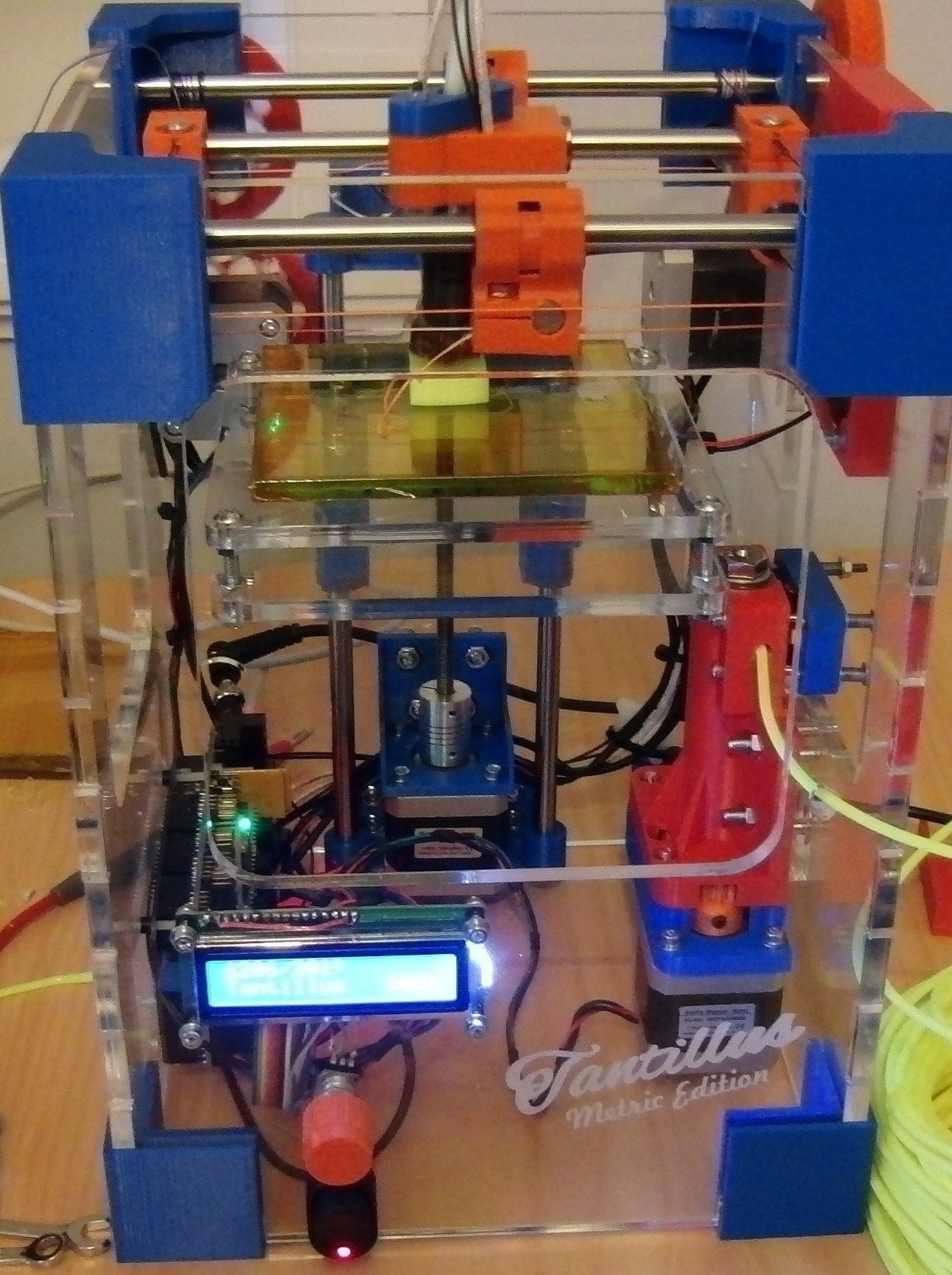
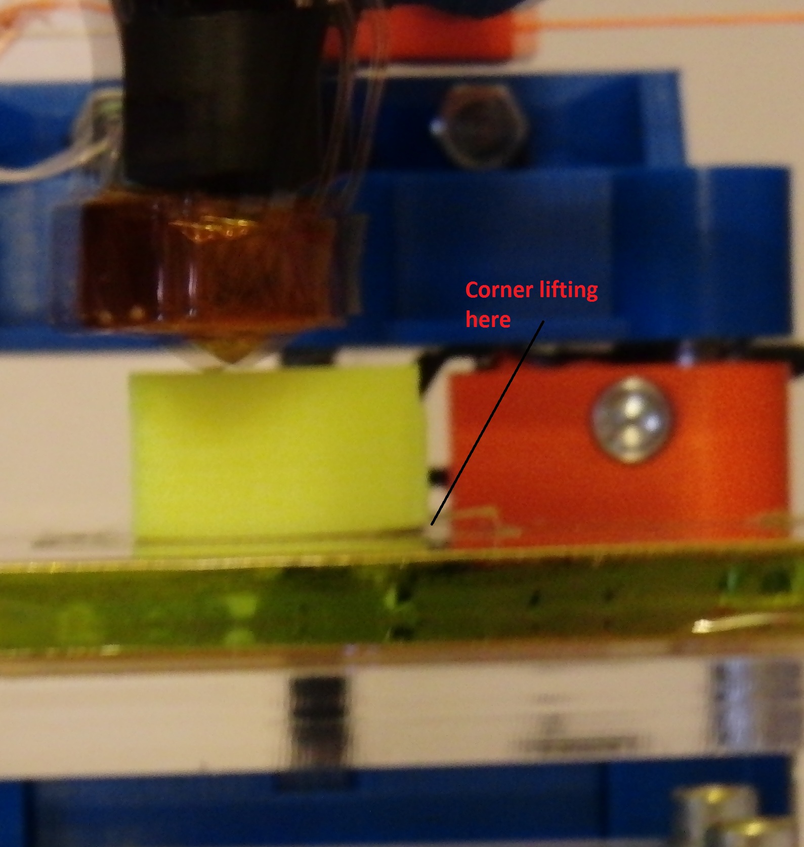
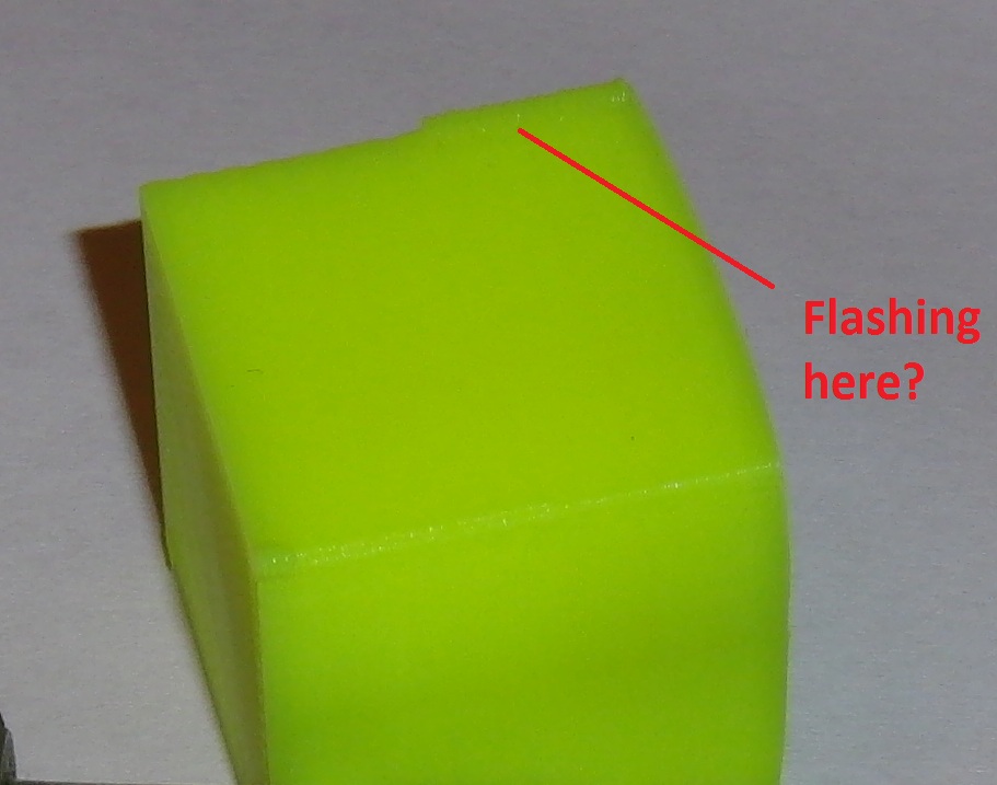
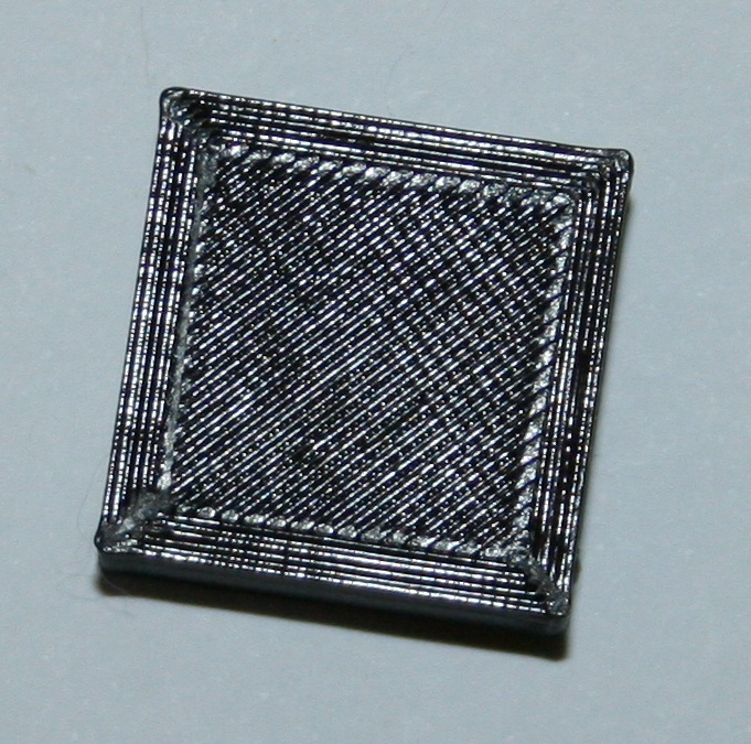
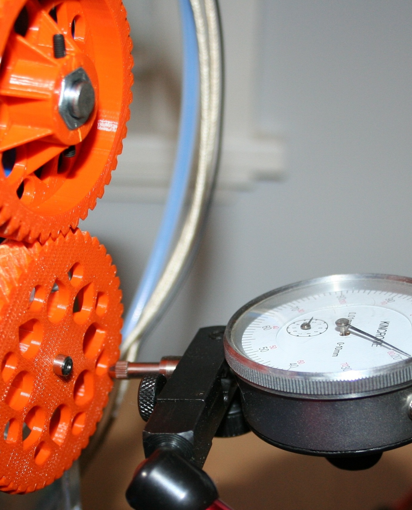
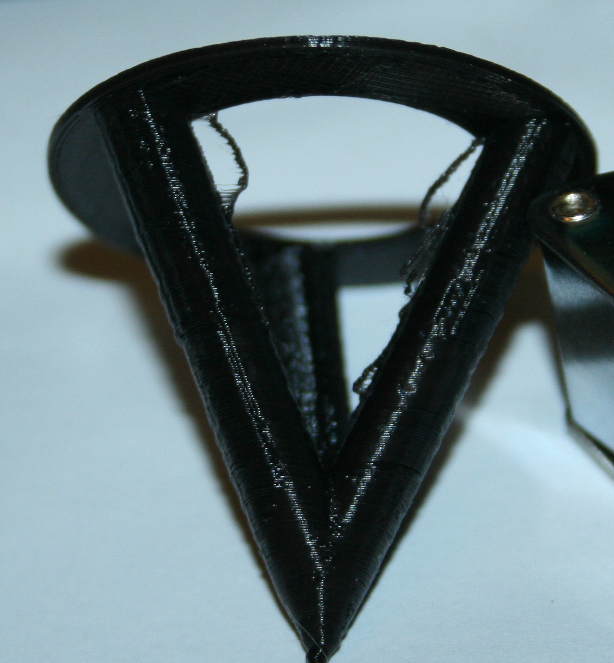
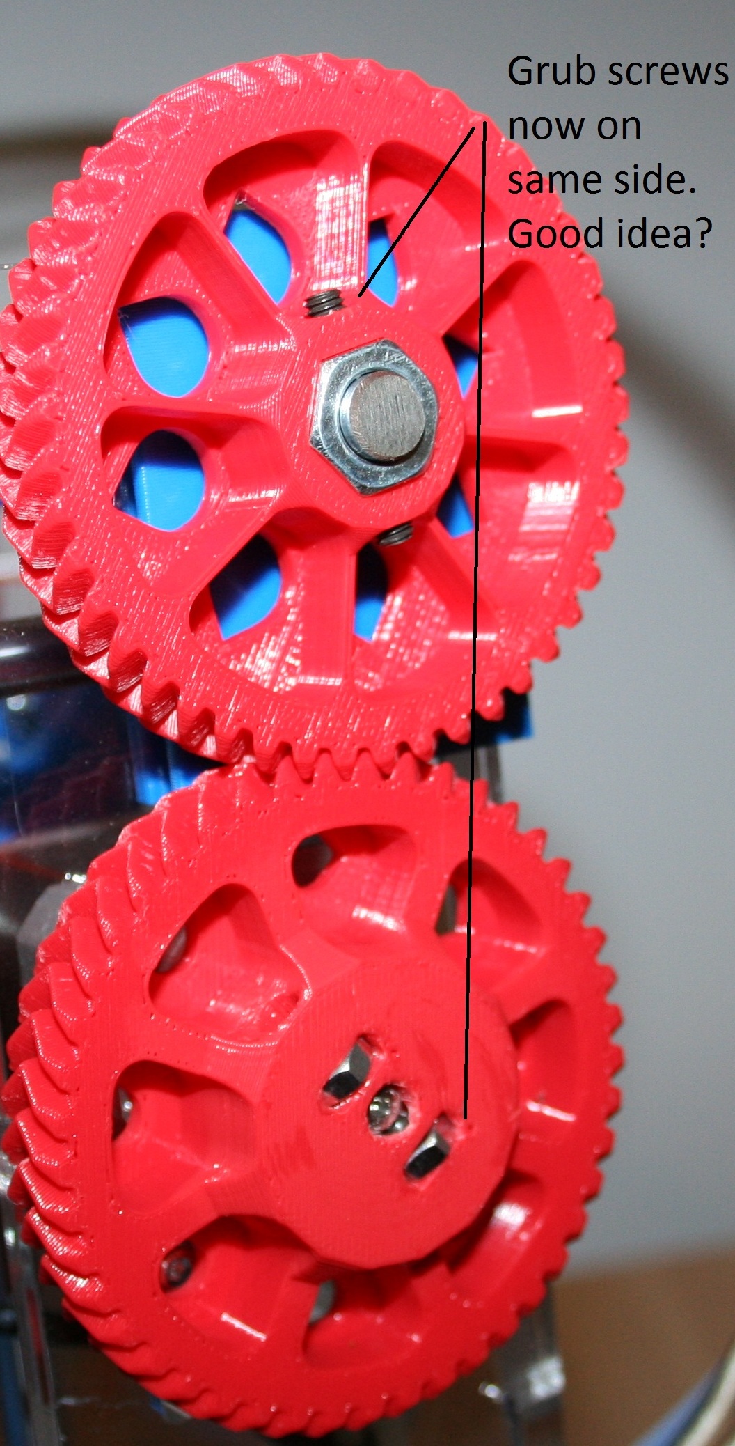
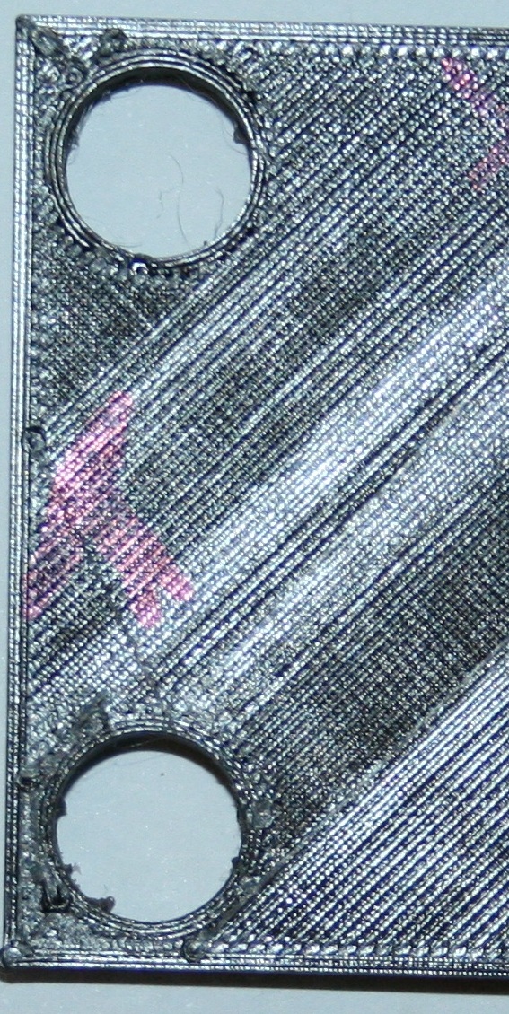
Sorry, only registered users may post in this forum.