Solidworks Metric Assembly
Posted by willworkforplastic
|
Re: Solidworks Metric Assembly September 26, 2012 05:22AM |
Registered: 13 years ago Posts: 2,947 |
willworkforplastic Wrote:
-------------------------------------------------------
> I have fixed the end-stop issue, and almost fixed
> the platter issues. However Sublime can you give
> me the dimensions of the glass. Can't find it
> anywhere on your BOM website page, maybe I am
> going blind however in my old age.
It fits between the bolt heads and measures 108mm wide (but with imperial bolts) and it is the depth of the entire bed 130mm.
> Once I have glass dimensions I will push version
> 0.6, (might even be time to call it 1.0?) and with
> this push I will include:
> Full SW/Edrawing/parasolid
> Full model STL
> All panels in DXF
> All individual STL's, including configuration
> specific ones like 4/5mm shafts etc.
One of the main reasons we use Git is because we do not need to keep renaming the versions and keeping old copies. You should remove the number from the file names and then let git copy over every time. It keeps track of all changes and you will always have access to them for as long as the repo exists. Just use the commit message to tell you what version or the change made. The reason mine had numbers until I released it was I actually have a bunch of completely different versions from development that I worked on simultaneously and were only on my computer and not git.
> On my printer, yes it is leaving bumps, so I'll
> try adjusting the temp. The filament was out of a
> sample mixed pack not on rolls so it probably has
> moisture in/just crap. I'll order in some proper
> full rolls hopefully that will be better. Anyhow
> see attached for the bump.
Those are pretty minor bumps. Does it leave any on the perimeter? Also if that picture was a top surface or solid infill I think you should increase your E-steps by 5 or 10. It looks a little to sparse.
>
> Out of interest who is your preferred supplier of
> filament sublime?
I actually use China filament from Repraper but it can have its issues with dirt or air bubbles etc. I do not recommend it for the beginner as it can be a source of problems and you need get a working machine before adding issues. I recommend some suppliers that have good reputations like in your neck of the woods I would recommend "Diamond age solutions" then there are places like Faberdashery in the UK, Ultimachine, Makergear in the US.
Edited 1 time(s). Last edit at 09/26/2012 05:23AM by Sublime.
| FFF Settings Calculator | Gcode post processors | Geometric Object Deposition Tool Blog |
| Tantillus.org | Mini Printable Lathe | How NOT to install a Pololu driver |
|
Re: Solidworks Metric Assembly September 27, 2012 04:14AM |
Registered: 11 years ago Posts: 111 |
Had to make glass 107mm wide to fit with tolerance between bolt heads, but such is.
Queue moron feeling, another reason I am not a programmer and git is good. I will fix revision issue.
And double key moron feeling for not picking diamond age up in a google search, I am shocked there is a local supplier and I only have to pay local shipping fee's. Such a good change for once. Usually I have to fork out $40 to $80 in shipping on little parts
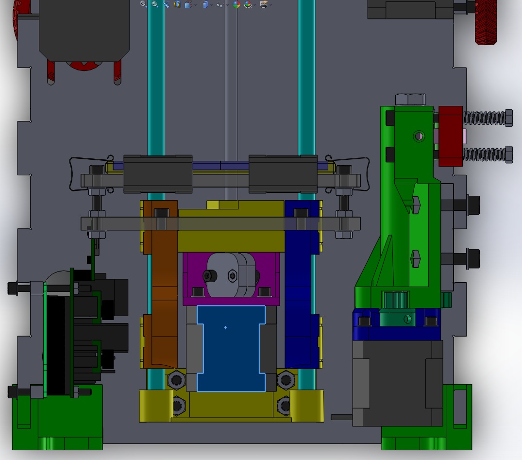
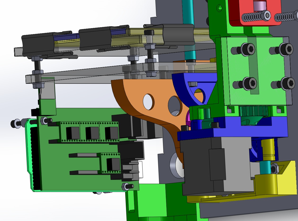
All good to do production files and push complete 'good' assembly, last thing I noticed is that SD card holder interferr's with bottom bed when the Z is full down. See attached screen shots. Is this right sublime and it is software limited not to crash? Reason I ask is your build instructions show it directly connected to shield and one of your gallery photo's show it double side taped to the inside of the front panel. At any rate better safe to ask than sorry.........
Queue moron feeling, another reason I am not a programmer and git is good. I will fix revision issue.
And double key moron feeling for not picking diamond age up in a google search, I am shocked there is a local supplier and I only have to pay local shipping fee's. Such a good change for once. Usually I have to fork out $40 to $80 in shipping on little parts
All good to do production files and push complete 'good' assembly, last thing I noticed is that SD card holder interferr's with bottom bed when the Z is full down. See attached screen shots. Is this right sublime and it is software limited not to crash? Reason I ask is your build instructions show it directly connected to shield and one of your gallery photo's show it double side taped to the inside of the front panel. At any rate better safe to ask than sorry.........
|
Re: Solidworks Metric Assembly September 27, 2012 04:53AM |
Registered: 13 years ago Posts: 2,947 |
The SDramps hitting the bed is a mistake on my part. I had been using large format SD readers (one taped to the front panel) and then I switched to SDramps which I tried in the original prototype that had the electronics lower. I raised the electronics to make more room below them for the wiring but caused this issue. I ordered cables to be made to move the SDramps board but they have not shown up yet. Eric used your model to make a bracket for the SDramps board [forums.reprap.org]
Diamond age is run by one of the very first RepRap team members Vik Olliver and has a good reputation for quality filament. I would buy from him if shipping to Canada wasn't so much.
Diamond age is run by one of the very first RepRap team members Vik Olliver and has a good reputation for quality filament. I would buy from him if shipping to Canada wasn't so much.
| FFF Settings Calculator | Gcode post processors | Geometric Object Deposition Tool Blog |
| Tantillus.org | Mini Printable Lathe | How NOT to install a Pololu driver |
|
Re: Solidworks Metric Assembly September 30, 2012 03:47AM |
Registered: 11 years ago Posts: 111 |
Ok, I have pushed latest model, everything should be pretty much sorted now. Also I have saved of DXF's for cutting and STL's for printing. However could bet the rent I have not got orientation correct in STL's for printing. But it all should help hopefully.
Eric if you email solid works files of your SD bracket I can include them in next push.
On my printer, sigh, I finally found what was giving me grief. The aluminium flexible coupler I was using was not clamping the M6 threaded rod enough. Just enough so it looked to be working, but not enough when it moved quickly it would slip. Solved with heat cure epoxy. Oh the pain it was causing me leveling the bed and calibrating the flow............ Just got to get gears printed and then all should be gravy.
Got some of that diamond age filament, and I see what you mean sublime, its really good. He even has a high impact version which I am keen to give a go might be good for gears/moving parts, maybe. I see he has a US distributor now as well: [www.printbl.com] don't know if he is cheap but might help you out with shipping costs.
|
Re: Solidworks Metric Assembly September 30, 2012 02:45PM |
Registered: 11 years ago Posts: 149 |
just sent them 
Holy crap, [shop.printbl.com] rocks! I was getting so friggin frustrated trying to find a high-quality vendor in the US with a good variety of different colored 3mm PLA that didn't come only on 5lb spools. And impact resistant grades? Yes please!
Video of a stretchy bracelet printed with the impact modified PLA from Diamond Age / printbl.com.
[www.youtube.com]
Edited 1 time(s). Last edit at 09/30/2012 02:47PM by Eric Young.
|
Re: Solidworks Metric Assembly October 03, 2012 05:24AM |
Registered: 11 years ago Posts: 111 |
So I started printing the metric versions of the gears in PLA on my tantillus, exciting times until, 2hrs in the plastic stopped extruding.
Seemed the hobbing on the hobbed bolt had been gunked up gradully with PLA from where it has been biting into the filament, sigh. I was running at (fine config 0.35mm nozzle) 390 flow, 45 max speed and 7mm retraction with 173oC nozzle temp. It was running really well until this happened.
The hobbing on the bolt is M4X0.7 and is sunk in 1.5mm. Stainless steel bolt at the moment, as that was all the engineering shop had when I went down to get one.
So my question sublime is should I up the hobbing size to M4.5X0.75 or M5X0.8 to better match #8-32 (which is M4.16X0.79), and then blunt of the hobbing to stop it cutting in and generating swarf that clogs the hobbing. Maybe reduce the sink in depth to 1.25mm and use a 4.8 steel steel bolt.
Heck I could even machine up a custom M4X1.0 tap if bigger pitch on the hobbing is better.
Or take the software path and reduce the max speed down to 35-40?
|
Re: Solidworks Metric Assembly October 03, 2012 06:43AM |
Registered: 13 years ago Posts: 2,947 |
Hard to say. I use a #8-32 tap to make my hobbed bolts because it was a little coarser than the metric equivalent. Also the tension on the idler needs to be fairly high. And last thing is if the E-steps are even 5 or 10 too high the extra steps will accumulate and after a 10-20 layers the pressure will be really high and cause it to slip if the idler is not tight enough. You may need to recalibrate the flow for 100 micron layers if you calibrated it using 150.
| FFF Settings Calculator | Gcode post processors | Geometric Object Deposition Tool Blog |
| Tantillus.org | Mini Printable Lathe | How NOT to install a Pololu driver |
|
Re: Solidworks Metric Assembly October 07, 2012 04:52PM |
Registered: 11 years ago Posts: 23 |
Today, taking advantage of a slow Sunday, I started assembly of the Tantillus. The panels were cut few weeks back, so they are based on Sublime's original repo. As I started printing the parts, your metric redesign came along. I printed the metric ones assuming that there are no changes to size of any part.
There I was with the original panels trying to fit the X/Y axis in and all seemed a bit mismatched. Finally I went back to Sublime's original XY ends, realising that then the metric carrige does not fit anymore. Only once have I changed to the original designs, all fit nicely.
@willworkforplastic - did you change not only openings for bolts and nuts, but actually dimensions of the plastic parts as well?
|
Re: Solidworks Metric Assembly October 09, 2012 05:07PM |
Registered: 13 years ago Posts: 2,947 |
Yeah mine is full of arbitrary numbers and I am sure WWFP made his using whole numbers.
| FFF Settings Calculator | Gcode post processors | Geometric Object Deposition Tool Blog |
| Tantillus.org | Mini Printable Lathe | How NOT to install a Pololu driver |
|
Re: Solidworks Metric Assembly October 12, 2012 04:12AM |
Registered: 11 years ago Posts: 111 |
Sorry for the late reply chaps, I have been a bit busy, and become a bit OCD about finding the perfect gear and hobbed bolt. See attached.
Still its a hard road mate finding the perfect hobbed bolt mate.
@mfeherpataky
I tried to make the parts as close as possible, but alas it sounds like they are not interchangeable. I would say there has been precision lost in me manually measuring the STL files in Solidworks.
From memory if I measured 10.17mm I would round to the nearest 0.25mm so it would become 10.25mm etc. However because you can not measure hole pitching well in mesh files as you have to go to points rather than circle entities error could have compounded from incorrect measurement. This could easily wind up being a 0.5mm difference I would say. No easy solution sorry. However I will put I note in about this in the drawings (I will get there.........).
One thing I found with the carriage which I believe is not your issue, but I will mention anyhow. Cast acrylic sheet can be off by +/-0.3mm from sheet to sheet in my experience. So when I went to cut the carriage spacer I hunted with a micrometer to find a good piece.
|
Re: Solidworks Metric Assembly October 12, 2012 03:20PM |
Registered: 11 years ago Posts: 149 |
Whoa lots of gears and hobbed bolts. And poor Jackie Chan he looks stressed out.
I'm with you on the hobbed bolt issue - I've taken to cleaning the grooves in mine after every 10 or so hours of printing because it seems that's around the time it's become filled up with PLA bits and starts to fail. It does seem to me like translucent filament fairs a little better and doesn't require the cleaning as frequently, maybe about half as much as opaque filament.
Is that white gear made of the impact modified PLA from Diamond Age? I got some last week and have yet to try printing it, is there any difference you noticed in the way it prints?
|
Re: Solidworks Metric Assembly October 13, 2012 04:23PM |
Registered: 11 years ago Posts: 23 |
Hi guys,
So what is your idea about metric Tantillus? Will it be merged back into Sublime's repo?
Main repo already has directory for metric parts, where a lone z-lift reside. But this suggest they are interchangeable.
I think that only XY axis has issue with the original case. The rest of metric parts - gears, Z-motor holder, extruder, should go without any problems with the original laser cut case. I will report how all goes along, as I continue the assembly. I am still waiting for some parts to do the job - j-head and the braided-line - no hard-core fishing types among family and friends.
@willworkforplastic - the redesign of extruder looks more solid and is easier to print, nice.
Thank you guys for you work, I am looking forward to this printer running.
|
Re: Solidworks Metric Assembly October 13, 2012 04:50PM |
Registered: 13 years ago Posts: 2,947 |
mfeherpataky Wrote:
-------------------------------------------------------
> Hi guys,
>
> So what is your idea about metric Tantillus? Will
> it be merged back into Sublime's repo?
> Main repo already has directory for metric parts,
> where a lone z-lift reside. But this suggest they
> are interchangeable.
Once there have been a couple printed and things are confirmed I will pull some of the parts into the Metric section of the original Repo but not until I know they are compatible with all the original parts.
| FFF Settings Calculator | Gcode post processors | Geometric Object Deposition Tool Blog |
| Tantillus.org | Mini Printable Lathe | How NOT to install a Pololu driver |
|
Re: Solidworks Metric Assembly October 14, 2012 06:01AM |
Registered: 11 years ago Posts: 111 |
@Eric,
Yeah hobbed bolts, sigh. I have learnt a lot though. At the moment I am running M6 and die springs (all I had lying around with a bit of grunt). Seems to work well, however I have the flow up at 500 and the speed at 30. So something still aint right. I'm going to try M5, just making a special tool up for it now. I'll post up the results in a separate thread when I know more.
Nada on the high impact material yet. I'm mastering normal material before I attempt others. The more I think about it however, the gears are probably best still done in normal PLA because you want them as hard as possible. Hinges however on my "keep it dry" would be good candidates for it.
The normal white diamond age PLA, I am printing at 160oC. Seems to print really well, but I have little experience in what is out there.
@mfeherpataky
Keep me posted with issues, and I will try to resolve best I can so they are interchangeable with original.
On the extruder, I never meant for it to be different, it was just Solidworks keep crashing with the STL model, and it was easier to CAD that way. Should only be minor differences.
@sublime
Good call on not pulling them into your repo until you know for certain they are interchangeable. I might try to overlap my model with yours to see if I can pick up any issues.
Just on a side note, I finally successfully printed a SW metric upper gear on my tantillus, however the base of it (bit on blue tape) pulled up by about 0.5mm. Blue tape appears to have pulled away from glass. Warp-age looks even around the gear however. Yet to test it if it is concentric warping, but is this how yours come out? Would a heated bed solve this issue if so?
It seems everything I print suffer's from this, so far it has been 3 gears and all your spool holders. I'm printing first layer at 200oC and after that 160oC. The only thing I can think is my flow rate is up to high, but when I turn it down 5 to 10 I can separate the lanes of filament in the print. Solid infill seems to make it really bad as well.
|
Re: Solidworks Metric Assembly October 14, 2012 06:37AM |
Registered: 13 years ago Posts: 2,947 |
Clean the glass with acetone before applying the tape and it usually sticks better. I have a bag of gears about the same size as yours that are warped and/or not perfect in some way. But I have also printed some 30+ machines worth of them. As for the hobbed bolt I am going to say you need much stronger springs on the idler. Every one of your hobbed bolts should be usable. My idler springs apply enough force that you can not pull it away by hand. Also tighten the nuts down until the springs are compressed until all the coils are touching each other but not over compressed. 160c may be too low to get good flow, the hotend will have molten plastic in it when you begin printing and then you will use it up and have to melt on demand which requires a higher temperature then we want the plastic to be at.
| FFF Settings Calculator | Gcode post processors | Geometric Object Deposition Tool Blog |
| Tantillus.org | Mini Printable Lathe | How NOT to install a Pololu driver |
|
Re: Solidworks Metric Assembly October 15, 2012 05:10AM |
Registered: 11 years ago Posts: 111 |
Sublime Wrote:
-------------------------------------------------------
> Clean the glass with acetone
Yeah I have been pretty OCD with that, since you recommended it in another thread.
> But I have also
> printed some 30+ machines worth of them.
Yeah that's what I figured, and my goal at the moment is to replicate your quality. I think my flow is up to high to compensate for the gear backlash and low temp like you say. I will try some more, print on print off master-san............ Some day I will have nice gears.
> the hobbed bolt I am going to say you need much
> stronger springs on the idler.
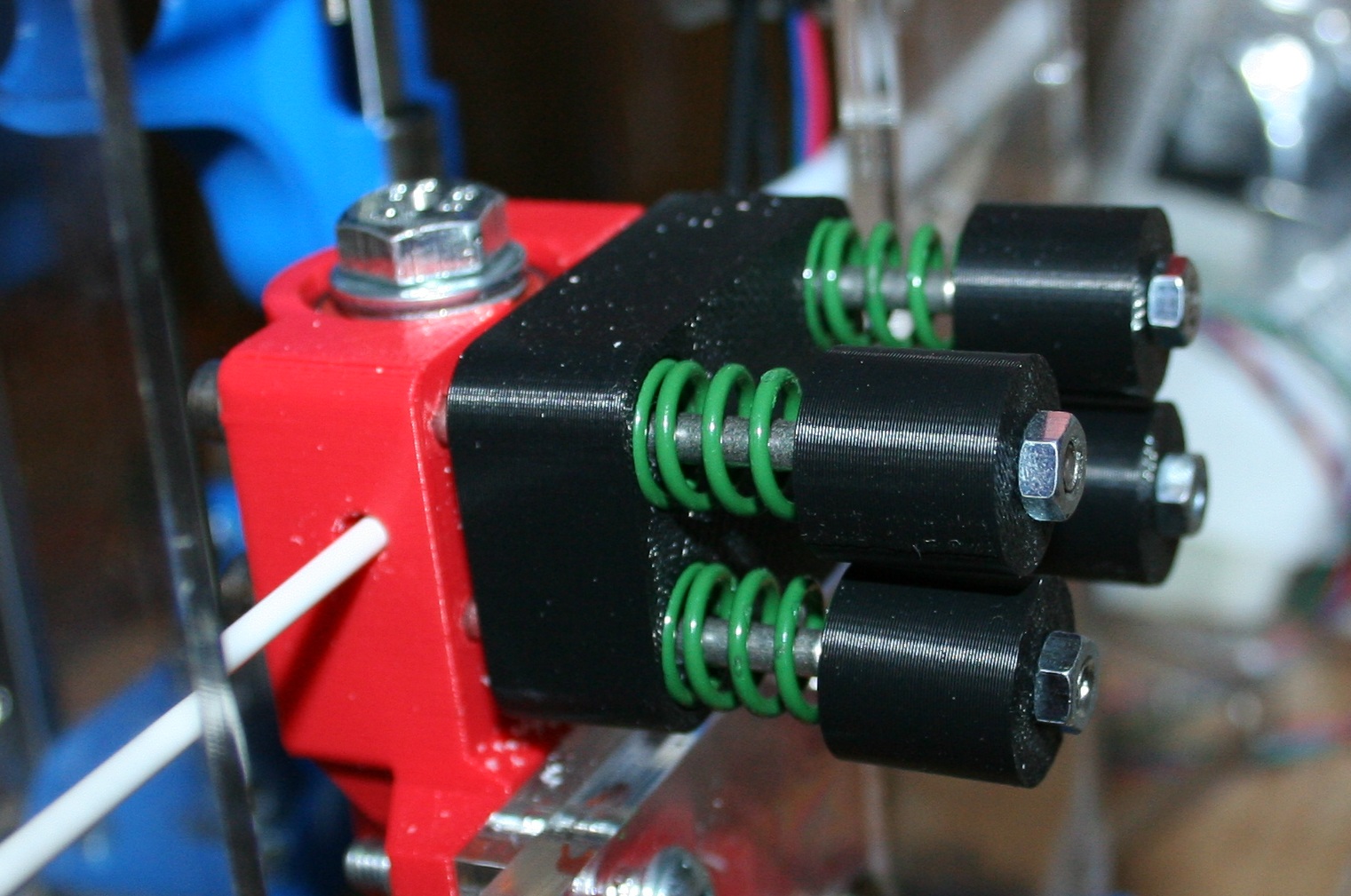
Yeah that is what I did using die springs I had lying around, works well now. I really can get good pressure without bottoming coils out. See attached photo. I think the original springs I was using where just too small. The current ones are over kill though.
> Every one of your
> hobbed bolts should be usable.
Yeah 1/2 of them are stainless which burred like a bitch under the microscope and I was too scared the burr would come off and block the hotend. 1/4 of them where either too shallow or to deep, some of them ran out of concentric as well. I'm probably just being a OCD however. At the moment I can not pull the filament through by hand so I think I am on the correct track now, it is just settings.
-------------------------------------------------------
> Clean the glass with acetone
Yeah I have been pretty OCD with that, since you recommended it in another thread.
> But I have also
> printed some 30+ machines worth of them.
Yeah that's what I figured, and my goal at the moment is to replicate your quality. I think my flow is up to high to compensate for the gear backlash and low temp like you say. I will try some more, print on print off master-san............ Some day I will have nice gears.
> the hobbed bolt I am going to say you need much
> stronger springs on the idler.
Yeah that is what I did using die springs I had lying around, works well now. I really can get good pressure without bottoming coils out. See attached photo. I think the original springs I was using where just too small. The current ones are over kill though.
> Every one of your
> hobbed bolts should be usable.
Yeah 1/2 of them are stainless which burred like a bitch under the microscope and I was too scared the burr would come off and block the hotend. 1/4 of them where either too shallow or to deep, some of them ran out of concentric as well. I'm probably just being a OCD however. At the moment I can not pull the filament through by hand so I think I am on the correct track now, it is just settings.
|
Re: Solidworks Metric Assembly October 17, 2012 06:56PM |
Registered: 11 years ago Posts: 23 |
Problems you say, the layers lines of your printed parts are great! I thought I had a good working printer, but this is just amazing.
I had some small wrapping issues with the gears as well, printed four sets already. Today I tried a non-coloured, cheap 16€/kg, PLA from www.reprapworld.com and got great flat and even gears. Maybe this would help. Small brim of 2-3mm also helps.
I had some small wrapping issues with the gears as well, printed four sets already. Today I tried a non-coloured, cheap 16€/kg, PLA from www.reprapworld.com and got great flat and even gears. Maybe this would help. Small brim of 2-3mm also helps.
|
Re: Solidworks Metric Assembly October 19, 2012 06:45AM |
Registered: 11 years ago Posts: 111 |
@mefeherpataky,
Yup this printer is awesome, the engineers at work must think so to because they I have a queue of 5 people wanting parts. I am just being a bit OCD getting the best I can out of it print on print off......... (Sublime can we buy parts from you as well?)
I am down to 0.1-0.2mm warpage on the gears now and it appears to be evenly concentric now. Are you getting better than that, I ask as simply I want to replicate other peoples results before I do stupid things like heated bed and other crazy mods....... (my low profile 50W concept heated bed is working on my desk at work though i'll post up in a separate thread when I actually get it going well).
And when you say brim, is that the skirt loops in slicer or the perimeters setting? Or are you referring to the outer wall thickness of the gear (4mm)?
Yup this printer is awesome, the engineers at work must think so to because they I have a queue of 5 people wanting parts
. I am just being a bit OCD getting the best I can out of it print on print off......... (Sublime can we buy parts from you as well?)I am down to 0.1-0.2mm warpage on the gears now and it appears to be evenly concentric now. Are you getting better than that, I ask as simply I want to replicate other peoples results before I do stupid things like heated bed and other crazy mods....... (my low profile 50W concept heated bed is working on my desk at work though i'll post up in a separate thread when I actually get it going well).
And when you say brim, is that the skirt loops in slicer or the perimeters setting? Or are you referring to the outer wall thickness of the gear (4mm)?
|
Re: Solidworks Metric Assembly October 22, 2012 12:14PM |
Registered: 11 years ago Posts: 23 |
Hi there again,
0.1-0.2 wrap evenly around the gear sounds great and nearly unnoticeable. I have a full bag of parts, some are flat as the glass bed supporting them, some have nearly no wrap, some I could use as a base for a rocking chair.
The flat ones, though were printed at a lower temperature and layers did not bond well, so serve to no good.
The good ones, have a minimal wrap that gives a good alignment in between the upper and motor gears. I think it will go over your 0.1-0.2 wrap.
Brim is what slic3r does, producing a few external perimeters only for the bottom layer - use 4-5 of those. Brim worked the best for me, skirt (just a border around the object) still helps if you print one single gear at a time positioning it at 0mm from the part. But then again, I did not run it in any scientific way. The best thing in slic3r is the brim and the bottom layer width set to 200%. The former lets the part stick better and yet it is easier to remove, the latter helps level any minor imperfections of the bed.
Now I am using Cura slicer - [daid.github.com], with great results, but it does not produce first layer that sticks as good as the one produced with slic3r. It uses skeinforge that runs few times faster then the original - some things slice faster then in slic3r. Daid, did a good job hiding skeinforge deep in the belly of this app with only a handful of settings exposed. So few in fact, that there is less possibly to set then in slic3r.
Next version will have the brim [github.com], but bottom layer width settings is something that skeinforge cannot take [github.com]. There is an nasty bug though when slicing multiple STLs at the same time - [github.com].
@Sublime - you should look into Cura, as it has what a bowden tube printer likes - comb. I still have not start my tantillus up, so I cannot comment on the print quality vs slic3r. It does produce cleaner lines for my current one though with much less retractions then in slic3r.
--
I am nearly there - all parts printed and assembled, now need few evenings to put electronics in place and kickstart a hybrid - metric tantillus based on the original laser cut housing.
|
Re: Solidworks Metric Assembly October 27, 2012 07:19AM |
Registered: 11 years ago Posts: 111 |
@mfeherpataky
Unfortunately/fortunately growing up in a tool room and now working in optics/microelectronics, it is just 2nd nature for me to pick up 0.1-0.2mm issues. My skype status says it all "isnt life odd when you work in µm" even the shortcut for µ is muscle memory for me.
So 0.1 to 0.2mm stands out like a sore thumb to me, sigh. Good to know this shouldn't cause me issues though, I will suppress my OCD tenancies from now on if the warpage is less than this.
Thanks for the call on the brim at 0mm, I deviated and printed some hinges using this technic and it helped. The parts stick so well to the bed! Another thing I found was pressing the blue tape as hard as possible onto the glass seems to help with the tape coming away from the glass.
Anyhow I have another 8Gb of ram in my machine now (long story), so I can get onto figuring out why the metric carriage/moving parts are not backwards compatible with the imperial laser cut frame. And yes do some drawings finally (like I say every time).
|
Re: Solidworks Metric Assembly October 27, 2012 12:47PM |
Registered: 11 years ago Posts: 18 |
You can add arbitrary brim to any STL with this SCAD script: [www.thingiverse.com]
Another thing I've found to help with 1st layer is putting down 2 layers of blue tape instead of 1 (adjust your Z axis to compensate), I get less curling and better adhesion. I don't know why it is.
Another thing I've found to help with 1st layer is putting down 2 layers of blue tape instead of 1 (adjust your Z axis to compensate), I get less curling and better adhesion. I don't know why it is.
|
Re: Solidworks Metric Assembly November 27, 2012 02:48PM |
Registered: 11 years ago Posts: 25 |
I have looked through the stl's for the metric Tantillus and found that in the Z-arm_2.stl needs a rotation along either x- or y-axis, else there is too much overhang :-)
Another issue is that slic3r does not like the supplied stl's. KiSSlicer can slice without problems + a stl exported from KiSSlicer can be sliced by slic3r without problems.
I have problems installing KiSSlicer on my production machine that runs an old version of Ubuntu because it is used for LinuxCNC, too.
/Niels
|
Re: Solidworks Metric Assembly November 27, 2012 05:40PM |
Registered: 11 years ago Posts: 18 |
I recommend NetFabb Cloud for fixing up STLs -- [cloud.netfabb.com], it's free, fast, and has fixed almost everything I've thrown at it. Some of the Tantillus STLs I had to run through more than once (notably the extruder body) before I got a good toolpath out of Kisslicer or Cura.
|
Re: Solidworks Metric Assembly November 28, 2012 07:45PM |
Registered: 11 years ago Posts: 149 |
oz9ny Wrote:
-------------------------------------------------------
> I have looked through the stl's for the metric
> Tantillus and found that in the Z-arm_2.stl needs
> a rotation along either x- or y-axis, else there
> is too much overhang :-)
I think you can just not lay down as may first layer loops, or make them closer to the part, or both. I made an STL with a different coordinate system anyways and it's attached, but it only buys about 1 more mm of real estate than the original. You will need to NetFabb it as j.samuels said above.
|
Re: Solidworks Metric Assembly December 06, 2012 07:38AM |
Registered: 11 years ago Posts: 41 |
Hello to all who are building a metric Tantillus, and thanks to WWFP for is fantastic work converting this machine to metric (and of course thanks to Sublime for his wonderfull desogn !)
I'm trying to check all the materials needed to create my own metric Tantillius, and I'm a bit lost when it comes to the fasteners.
I checked WWFP files for holes sizes and length, but I couldn't get anything correct (maybe it's me ...). I was wondering If my approximations (imp -> met) would works when I'll be fastening all the bits together :
I known I shouldn't worry about something as simple as some fastener, but I don't want my printer to wobble like a drunken bot !
I'm trying to check all the materials needed to create my own metric Tantillius, and I'm a bit lost when it comes to the fasteners.
I checked WWFP files for holes sizes and length, but I couldn't get anything correct (maybe it's me ...). I was wondering If my approximations (imp -> met) would works when I'll be fastening all the bits together :

I known I shouldn't worry about something as simple as some fastener, but I don't want my printer to wobble like a drunken bot !
|
Re: Solidworks Metric Assembly December 06, 2012 02:40PM |
Registered: 11 years ago Posts: 25 |
|
Re: Solidworks Metric Assembly December 06, 2012 04:19PM |
Registered: 13 years ago Posts: 2,947 |
To be honest it looks like you have used the head diameter of the imperial bolts not the shaft diameter to do your conversion which makes them all wrong. Also I would use smaller rather than larger in most cases (like the threaded rod should be 6mm)
Check here [en.wikipedia.org] it tells you all the sizes of each imperial bolt in metric (#10 = 4.82mm)
Check here [en.wikipedia.org] it tells you all the sizes of each imperial bolt in metric (#10 = 4.82mm)
| FFF Settings Calculator | Gcode post processors | Geometric Object Deposition Tool Blog |
| Tantillus.org | Mini Printable Lathe | How NOT to install a Pololu driver |
|
Re: Solidworks Metric Assembly December 07, 2012 10:22PM |
Registered: 11 years ago Posts: 111 |
hi Nico3ck
I have managed to start re-visiting my metric conversion of the design to get it compatible with imperial version, and I have noticed a few mistakes on my behalf:
1. Corner snap hocks differ to imperial ones
2. One of the laser cut panels has a 0.25mm bearing hole pitch mistake
3. Not enough clearance in the 8mm holes on the XY ends should be 8.2mm
So I will correct as soon as possible.
If you can hold out for a week, I will get a BOM drawing together similar to the one I did for the keep it dry which will list fasteners in it for you to make your life easier. As a rule of thumb I have used M3/M4/M5 in the design just cause there common.
|
Re: Solidworks Metric Assembly December 10, 2012 09:16AM |
Registered: 11 years ago Posts: 41 |
|
Re: Solidworks Metric Assembly December 11, 2012 01:47AM |
Registered: 11 years ago Posts: 111 |
Hey Sublime, I have been checking over the SW model and I just wanted to check on the XY ends the majority of the hole for the printed bush is suppose to be 15.5mm diameter. I assume the bush being 15mm only engages on the last bit of the hole being, and as per your instructions you drill into bush and bolt then holds bush in.


Sorry, only registered users may post in this forum.