Solidworks Metric Assembly
Posted by willworkforplastic
|
Re: Solidworks Metric Assembly December 11, 2012 05:00AM |
Registered: 13 years ago Posts: 2,947 |
willworkforplastic Wrote:
-------------------------------------------------------
> Hey Sublime, I have been checking over the SW
> model and I just wanted to check on the XY ends
> the majority of the hole for the printed bush is
> suppose to be 15.5mm diameter. I assume the bush
> being 15mm only engages on the last bit of the
> hole being, and as per your instructions you drill
> into bush and bolt then holds bush in.
Sounds correct. The bushing is a loose push fit into the 15.5mm hole and the smaller portion of the hole just needs to be large enough for the rod to fit through without any friction. It is there to stop the bushing from going all the way through. My original thought was to add a notch in the bushing for the set screw in the model so it is printed and that would require one end being captive. The problem was getting the bushing in in the correct orientation so drilling ended up being easier and the captive end is still there.
| FFF Settings Calculator | Gcode post processors | Geometric Object Deposition Tool Blog |
| Tantillus.org | Mini Printable Lathe | How NOT to install a Pololu driver |
|
Re: Solidworks Metric Assembly December 14, 2012 07:03AM |
Registered: 11 years ago Posts: 111 |
Right, I am just pushing new files to github now. Basically all updated to be backwards compatible with original imperial design, plus a few hacks included for anybody interested. See readme for full details. Also production files all there, no nested files, but I did check them all with Netfab this time, so hopefully they are better than last time.
I am going to Laser cut and print both versions of the machine out to check what I can over the xmas break hopefully. Hopefully that will put things to rest with backwards compatibility.
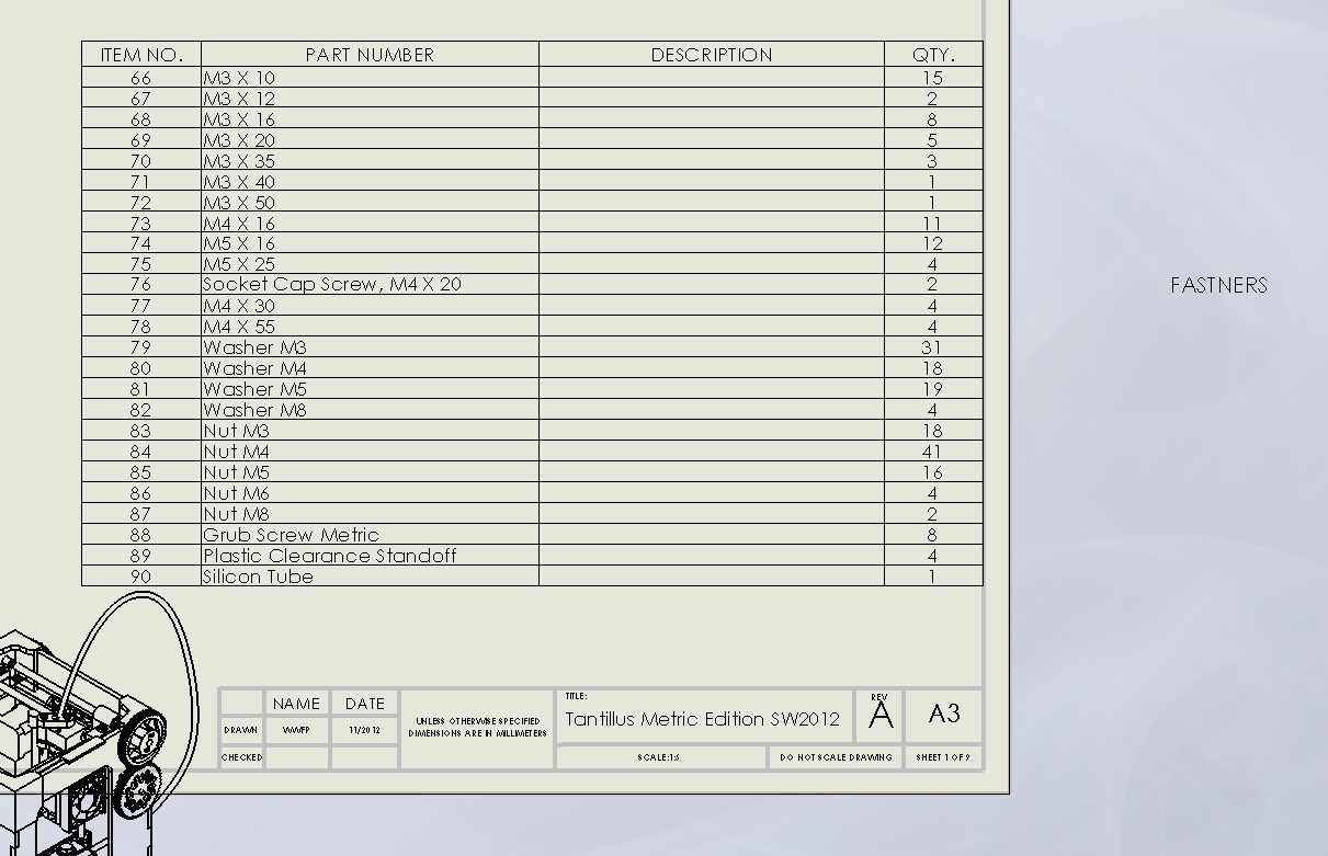
Drawings are coming along way slower than I thought (so much info to convey), but they are slowly getting there (8 pages so far.....). @Nico3ck I have attached a screen dump of the fastener section of the overall BOM, I have not checked it yet, but it should be a good start for you.
I am going to Laser cut and print both versions of the machine out to check what I can over the xmas break hopefully. Hopefully that will put things to rest with backwards compatibility.
Drawings are coming along way slower than I thought (so much info to convey), but they are slowly getting there (8 pages so far.....). @Nico3ck I have attached a screen dump of the fastener section of the overall BOM, I have not checked it yet, but it should be a good start for you.
|
Re: Solidworks Metric Assembly December 14, 2012 09:50AM |
Registered: 11 years ago Posts: 41 |
|
Re: Solidworks Metric Assembly December 17, 2012 10:08AM |
Registered: 14 years ago Posts: 20 |
|
Re: Solidworks Metric Assembly December 18, 2012 05:12AM |
Registered: 11 years ago Posts: 111 |
Hacks/laser cutting machines basically, at this stage:
All Panels 6mm - This is the standard design for metric, or the safe option. Essentially a copy of the original design. Probably best to stick to this.
All Panels 6mm VLS6_60 0_1mm Offset - This has been panelized for a laser cutter bed size of 457 X 812 and the outter/bearing dims offset by 0.1mm (laser spot size of 0.2mm) so if you have access to 22mm hand reamer you can really get the bearing holes spot on.
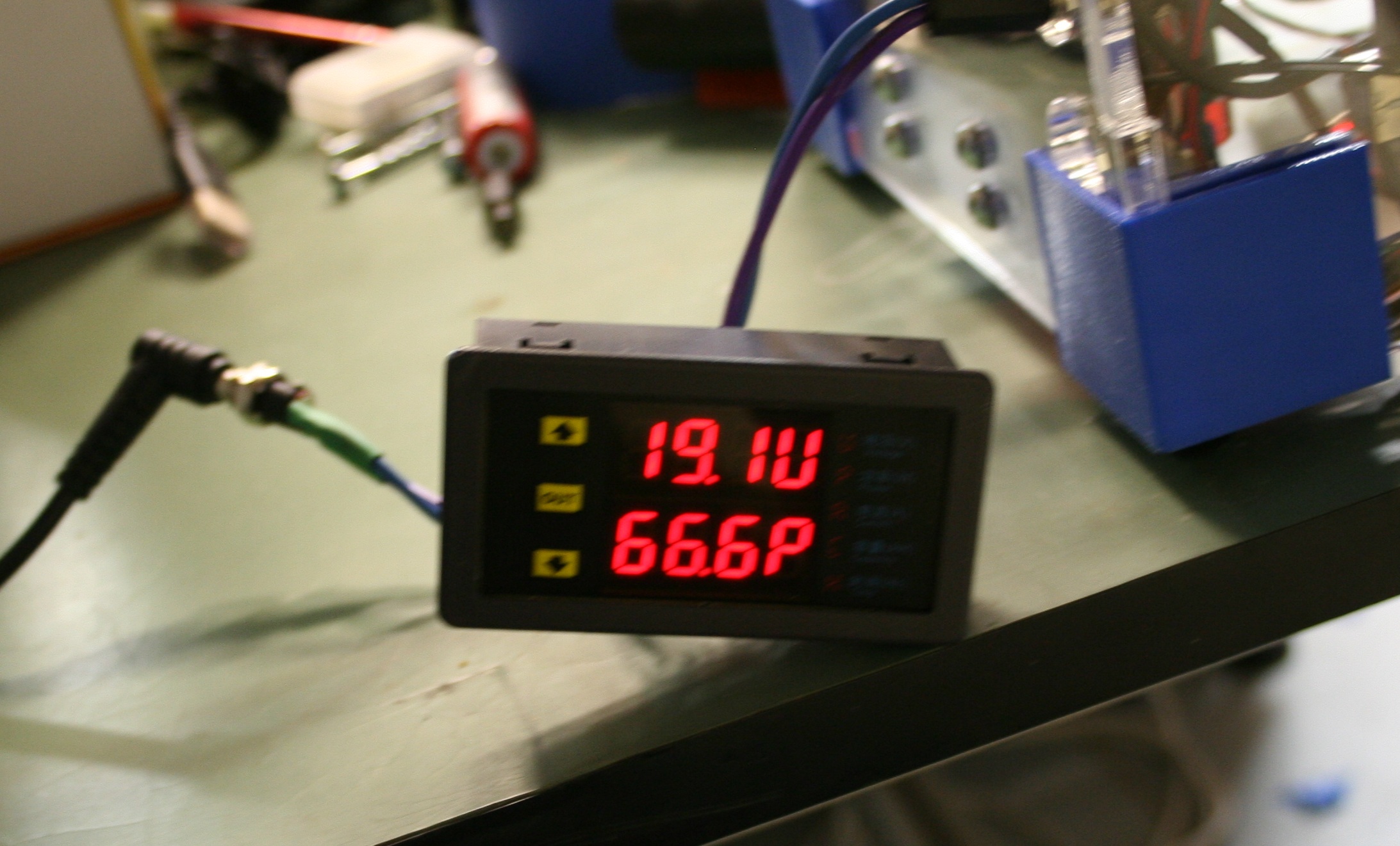
All Panels 6mm VLS6_60 0_1mm Offset WITH VI METER HACK - same as above but a hack for a voltage/current/power meter I am putting in for future reference when I do a heated bed so I can monitor power usage. See attached photo's if you are interested.
Also I have just today laser cut the original design (imperial) and the copy design (metric) to do a bit of a build comparison of designs. Plan is to print both metric and imperial parts and try them out together. Any errors I will update as soon as I find them. I am hoping to do this all over the xmas break, assuming work lets me have a break.........
To avoid confusion in the future I will move the hacked dxf's to the hack folder. Plus I will get a test laser cutting dxf up as well.
All Panels 6mm - This is the standard design for metric, or the safe option. Essentially a copy of the original design. Probably best to stick to this.
All Panels 6mm VLS6_60 0_1mm Offset - This has been panelized for a laser cutter bed size of 457 X 812 and the outter/bearing dims offset by 0.1mm (laser spot size of 0.2mm) so if you have access to 22mm hand reamer you can really get the bearing holes spot on.
All Panels 6mm VLS6_60 0_1mm Offset WITH VI METER HACK - same as above but a hack for a voltage/current/power meter I am putting in for future reference when I do a heated bed so I can monitor power usage. See attached photo's if you are interested.
Also I have just today laser cut the original design (imperial) and the copy design (metric) to do a bit of a build comparison of designs. Plan is to print both metric and imperial parts and try them out together. Any errors I will update as soon as I find them. I am hoping to do this all over the xmas break, assuming work lets me have a break.........
To avoid confusion in the future I will move the hacked dxf's to the hack folder. Plus I will get a test laser cutting dxf up as well.
|
Re: Solidworks Metric Assembly December 19, 2012 03:07AM |
Registered: 11 years ago Posts: 111 |
|
Re: Solidworks Metric Assembly April 07, 2013 03:53AM |
Registered: 11 years ago Posts: 111 |
Finally got some time (got of my lazy arse) and finished the Bom/Assembly drawings!
I have pushed all the files up on github (https://github.com/willworkforplastic/Tantillus).
Can people take a look at the pdf and try and find errors/anything more useful information that should be in them. Keep in mind they are really only a supplement to the build instructions on tantillus.org however.
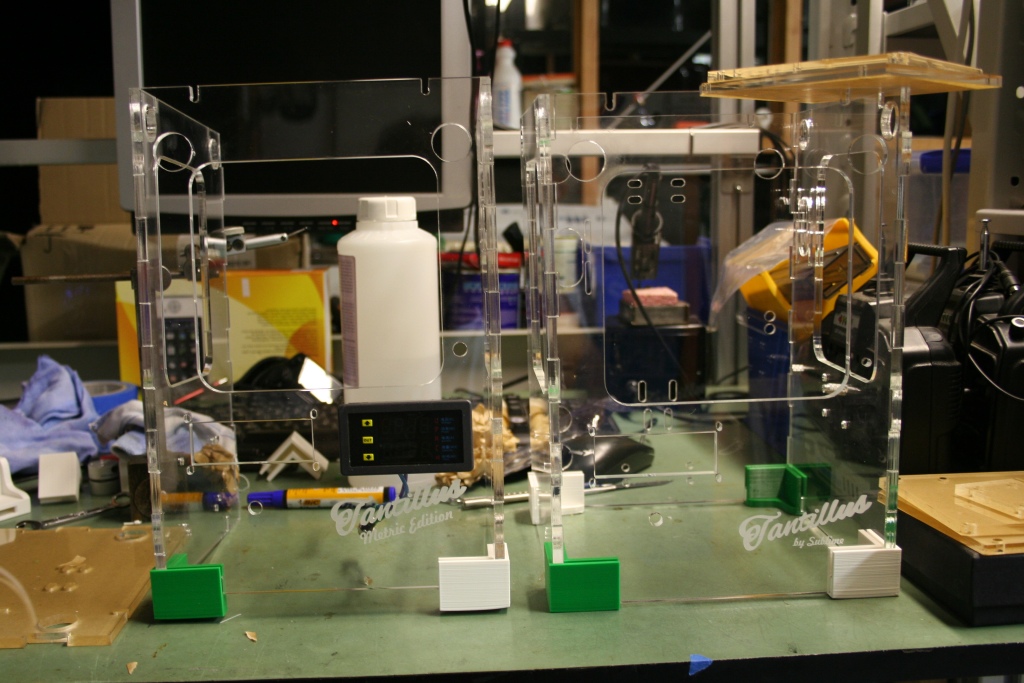
Also I have been doing a physical metric/imperial check, all has gone well so far as you can see (green = metric/white = imperial):

I have handed them off to people to complete now, so I will keep an eye on any issues they may have.
Also I have included configs for various hacks I have been playing around with. None of them are fully tested yet, so be careful using them. Sorry sublime SW just keeps crashing when I try to generate a STL of my hacked config. But the hacked config is within the edrawing file (.EASM) so if you want to have a look at it you can download edrawings for free (http://www.edrawingsviewer.com/) and use the easm file. There should be two configs in it (2nd tab down left hand side).
As for the 2 major hacks, the heated bed and the ball screw. I just got them running today. The heated bed seems to work (heaps more testing required) and the ball screw did not solve my layer consistency issue (thinking it is the hobbed bolt not running concentric now). I will post up a seperate thread about them once I have some decent data. Anyhow this is what it all looks like at the moment (i'll do a decent post about the wins/fails I have been through soon):

I have pushed all the files up on github (https://github.com/willworkforplastic/Tantillus).
Can people take a look at the pdf and try and find errors/anything more useful information that should be in them. Keep in mind they are really only a supplement to the build instructions on tantillus.org however.
Also I have been doing a physical metric/imperial check, all has gone well so far as you can see (green = metric/white = imperial):
I have handed them off to people to complete now, so I will keep an eye on any issues they may have.
Also I have included configs for various hacks I have been playing around with. None of them are fully tested yet, so be careful using them. Sorry sublime SW just keeps crashing when I try to generate a STL of my hacked config. But the hacked config is within the edrawing file (.EASM) so if you want to have a look at it you can download edrawings for free (http://www.edrawingsviewer.com/) and use the easm file. There should be two configs in it (2nd tab down left hand side).
As for the 2 major hacks, the heated bed and the ball screw. I just got them running today. The heated bed seems to work (heaps more testing required) and the ball screw did not solve my layer consistency issue (thinking it is the hobbed bolt not running concentric now). I will post up a seperate thread about them once I have some decent data. Anyhow this is what it all looks like at the moment (i'll do a decent post about the wins/fails I have been through soon):
|
Re: Solidworks Metric Assembly April 07, 2013 04:09AM |
Registered: 13 years ago Posts: 2,947 |
Looking good. I like the filament feed bracket. Is the PID controller for the heated bed and/or the hotend?
Also the banding may be a result of the filament being really sensitive to temperature changes from the bang bang heat control. If you would like to you can change the config file for the firmware to use PID and then run the PID autotune command M303 from pronterface a few times and record the results and average them and then enter them in the config file and reupload.
Note I find with PID it does not react as fast as bang bang so having vastly different speeds on the perimeter/infill does not always work that well with the PLA I use.
| FFF Settings Calculator | Gcode post processors | Geometric Object Deposition Tool Blog |
| Tantillus.org | Mini Printable Lathe | How NOT to install a Pololu driver |
|
Re: Solidworks Metric Assembly April 07, 2013 04:41AM |
Registered: 11 years ago Posts: 111 |
> Looking good. I like the filament feed bracket.
Yeah I had to because the filament kept diving down the side of the diamond age spools and jamming. It would only occur about once every 20hrs of printing but it was so frustrating.
> Is the PID controller for the heated bed and/or the
> hotend?
If you are referring to the 7 seg display on the front panel of the machine that is actually to monitor the power the machine is drawing. Just so I do not max out the 19V/180W PSU during heated bed testing. I was sick of connecting up multi-meters. It was only about $20USD from china, does voltage/current/power. Think they are used for solar setups.
The yellow box in front of the machine is a data logger I am borrowing to log temps.
All the temperature control is done by the ramps.
> Also the banding may be a result of the filament
> being really sensitive to temperature changes from
> the bang bang heat control. If you would like to
> you can change the config file for the firmware to
> use PID and then run the PID autotune command M303
> from pronterface a few times and record the
> results and average them and then enter them in
> the config file and reupload.
I am using the PID option in marlin, as the bang bang method seemed to give me a hysteresis of 10-5oC after I fixed the thermistor in the hotend which died on me. Long story about thermal pastes....... Anyhow thanks for the M303 trick (i'll try that now), I was manually tuning. Done it roughly but the head only seems to have about 2oC of hysteresis now. I'll do some head temp logging when I do the heated bed logging anyhow to see how much it actually varies.
|
Re: Solidworks Metric Assembly April 29, 2013 03:42AM |
Registered: 11 years ago Posts: 111 |
|
Re: Solidworks Metric Assembly May 01, 2013 03:53PM |
Registered: 13 years ago Posts: 2,947 |
OK I finally had time to download and go through your PDF.
First thing is wow it is amazing.
On to the issues or things I saw that may not be correct.
1) You have the J-head on there twice in the list of parts 90 and 91
2) On page 6 you show the XY cross bars sticking out of the XY ends. This needs to be either short enough to not stick out or long enough that the Spectra can not rub on the end and fray. If they just stick out a little it is easy to fray the cable as it passes by over and over (learnt this the hard way on the very first machine during testing).
3) You have four bulldog clips but I am not sure how you have the second two attached. For me they are either too short and won't touch the glass or too long and hit the hotend when printing the full size of the bed.
Because of all the SW files in your Repo it is a little large to download if all you want to see is your PDF so I am hosting a copy of it on my server. The link is [www.Tantillus.org] and if you would like l can add links to this thread, your repo and your instructions to Tantillus.org (as well as Attribution to you) for people that want to build a Metric machine.
Edited 1 time(s). Last edit at 05/01/2013 03:54PM by Sublime.
| FFF Settings Calculator | Gcode post processors | Geometric Object Deposition Tool Blog |
| Tantillus.org | Mini Printable Lathe | How NOT to install a Pololu driver |
|
Re: Solidworks Metric Assembly May 13, 2013 11:09AM |
Registered: 11 years ago Posts: 203 |
willworkforplastic Wrote:
> this.
>
> All Panels 6mm VLS6_60 0_1mm Offset - This has
> been panelized for a laser cutter bed size of 457
> X 812 and the outter/bearing dims offset by 0.1mm
> (laser spot size of 0.2mm) so if you have access
> to 22mm hand reamer you can really get the bearing
> holes spot on.
>
Cut this on a Versalaser VL200 at the week and found some bearing push into the holes fine and other are still very tight so will most likely need reaming or drilling so what would be acceptable?
[www.ebay.co.uk]
or
[www.ebay.co.uk]
Thanks
Ben
|
Re: Solidworks Metric Assembly May 13, 2013 12:46PM |
Registered: 11 years ago Posts: 78 |
|
Re: Solidworks Metric Assembly May 15, 2013 11:04PM |
Registered: 11 years ago Posts: 111 |
Sorry for the late reply chaps, stuck in Thailand in a clean room trying to explain things to thai people in english.......... sigh.
@Sublime
All good on drawings, I will make changes and put your name in the checked box. Then update the repository. Cheers for hosting them on your site I to was getting worried about the size of the repo. Good to see they where not a waste of my time as well.
@Plexer
Cheers for the PM reminding me to answer this stuff. Again sorry for the late reply.
You will need a hand reamer. Just run it through carefully, and do not use any oils as cutting fluid. Water is a good cutting fluid for acrylic, however you have to oil the reamer after use and then degrease it next time you want to use it.
A step drill is usually used for sheet metal work. They are a very handy piece of kit to have. I use one on a slow speed in acrylic to drill 4/6/8mm holes tends not to crack the acrylic like a standard drill bit.
@goopyplastic
chur bro (thanks heaps)
|
Re: Solidworks Metric Assembly May 16, 2013 03:47AM |
Registered: 11 years ago Posts: 78 |
|
Re: Solidworks Metric Assembly May 16, 2013 05:23AM |
Registered: 11 years ago Posts: 203 |
|
Re: Solidworks Metric Assembly May 30, 2013 06:31AM |
Registered: 11 years ago Posts: 203 |
|
Re: Solidworks Metric Assembly May 30, 2013 10:38AM |
Registered: 11 years ago Posts: 203 |
|
Re: Solidworks Metric Assembly July 16, 2013 04:40PM |
Registered: 12 years ago Posts: 14 |
Hi,
Has anyone printed a fully functioning tantallus from the metric files?
I printed the extruder body last night but the nut-traps for the nuts which connect the extruder body to the motor mount seem to be the incorrect size.... (1 is m4, but the rest certainly are not). I don’t want to print out another part and find it doesn’t fit either :/
Also does anyone know of a source (preferably UK based) for the hobbed bolt for the extruder?
|
Re: Solidworks Metric Assembly July 17, 2013 05:40AM |
Registered: 11 years ago Posts: 41 |
|
Re: Solidworks Metric Assembly September 07, 2013 05:41AM |
Registered: 11 years ago Posts: 111 |
Right finally got of my lazy arse and did some updates:
@Sublime:
X/Y Bars are now 170mm long. Changed from 175mm.
Changed the Hotend double up on the BOM to a single line
Removed two of the bulldog clips
Drawing PDF now at REV B, so you might want to update the one on your website.
@Goopyplastic:
Thanks for picking up the M4 nut mistake in the carriage, I have changed them to M3 now.
@Plexer:
Thanks for picking up the XY end hole mistake, no idea why this happened, but I have fixed now. I was wondering why I had to drill them out, but I never remembered to fix the issue once I sat down on my PC inside (Tantillus is in the garage).
@MK:
Thanks for picking up on the hex holes in the extruder body. For some reason I made them 7.2/8mm across flats. They are now both 7.5mm. In your case I would assume the M4 nuts you are using are up on 7mm (across flats) or the printed parts you are using are down. A bit of needle filing on the hex holes should sort you out. I think at this stage I have built the Tantillus 4 times and there are 7 other people I know who are building them.
Also in the Solidworks model there is a hacked config for my dry box feeder system which looks like this (still a work in progress so be careful using the hacked model):
And I got a quick lesson at my new job with Keyshot, so I just had to play:
It was amazing how easy it was. There are a few more angles in a rendering folder in my github. Sublime if you want any for yourself webpage, I'd be more than happy to do them for you.
I'm just trying to sync my repo now but having some technical difficulties (failed to sync this branch error...... gotta do some research to why), I'll post up once its actually sync'ed correctly.
@Sublime:
X/Y Bars are now 170mm long. Changed from 175mm.
Changed the Hotend double up on the BOM to a single line
Removed two of the bulldog clips
Drawing PDF now at REV B, so you might want to update the one on your website.
@Goopyplastic:
Thanks for picking up the M4 nut mistake in the carriage, I have changed them to M3 now.
@Plexer:
Thanks for picking up the XY end hole mistake, no idea why this happened, but I have fixed now. I was wondering why I had to drill them out, but I never remembered to fix the issue once I sat down on my PC inside (Tantillus is in the garage).
@MK:
Thanks for picking up on the hex holes in the extruder body. For some reason I made them 7.2/8mm across flats. They are now both 7.5mm. In your case I would assume the M4 nuts you are using are up on 7mm (across flats) or the printed parts you are using are down. A bit of needle filing on the hex holes should sort you out. I think at this stage I have built the Tantillus 4 times and there are 7 other people I know who are building them.
Also in the Solidworks model there is a hacked config for my dry box feeder system which looks like this (still a work in progress so be careful using the hacked model):

And I got a quick lesson at my new job with Keyshot, so I just had to play:

It was amazing how easy it was. There are a few more angles in a rendering folder in my github. Sublime if you want any for yourself webpage, I'd be more than happy to do them for you.
I'm just trying to sync my repo now but having some technical difficulties (failed to sync this branch error...... gotta do some research to why), I'll post up once its actually sync'ed correctly.
|
Re: Solidworks Metric Assembly September 07, 2013 07:36AM |
Registered: 11 years ago Posts: 111 |
Hmmm we seem to be experiencing some technical difficulties with getting my repo updated, looks like file corruption hopefully it is only my local repo and not my working directory, never fear I'll get the guys on the case:
and hopefully it will be fixed in the next day or two.

and hopefully it will be fixed in the next day or two.
|
Re: Solidworks Metric Assembly September 07, 2013 07:37AM |
Admin Registered: 12 years ago Posts: 819 |
This is really great work, thanks @willworkforplastic for doing this. I'm definitely wanting a tantillus since i first saw it and your work makes it much easier to build now.
I think i got all the questions solved slowly and also found someone to laser cut the acrylic for a reasonable price so i guess i'll do one - fishing line will arrive from china anytime soon i hope
Edited 1 time(s). Last edit at 09/07/2013 07:38AM by Helmi.
Frank
I think i got all the questions solved slowly and also found someone to laser cut the acrylic for a reasonable price so i guess i'll do one - fishing line will arrive from china anytime soon i hope
Edited 1 time(s). Last edit at 09/07/2013 07:38AM by Helmi.
Frank
|
Re: Solidworks Metric Assembly September 07, 2013 11:55PM |
Registered: 11 years ago Posts: 111 |
|
Re: Solidworks Metric Assembly September 13, 2013 08:01PM |
Registered: 13 years ago Posts: 2,947 |
I will try and get things on my end set up for your version when time permits.
Your machine has really evolved. Did you find all the bracing was needed in the corners or just overkill because you can?
Your machine has really evolved. Did you find all the bracing was needed in the corners or just overkill because you can?
| FFF Settings Calculator | Gcode post processors | Geometric Object Deposition Tool Blog |
| Tantillus.org | Mini Printable Lathe | How NOT to install a Pololu driver |
|
Re: Solidworks Metric Assembly September 24, 2013 05:12AM |
Registered: 11 years ago Posts: 111 |
> Your machine has really evolved. Did you find all
> the bracing was needed in the corners or just
> overkill because you can?
Yeah some days I recon I enjoy hacking the machine more than actually 3D printing stuff.........
As for the bracing, the reason I did it was I was trying to solve that layer inconstancy I was having. I was always taught in machine building that rigidity is king. So that is the way I went, glued the panels together with wicking grade acrylic glue, added the top and bottom braces via bolts and glued internal corner pieces. It however did not solve the layer inconstancy, but the printer is one strong cube now. If I did it over again, I would just put the top and bottom braces on via bolts and leave out the internal corners because they just get in the way. So yeah it was a bit of overkill/not needed/fail, however if I ever need to throw my printer at someone and then print something it will still work.
On the layer inconstancy, after installing an epic-ally expensive ball screw It was still present, however under the microscope I noticed the pattern was pitched at 1mm, no matter the printed part geometry. My thought was 1mm = 1 turn off the stepper, and a friend told me cheap Chinese steppers are not great at holding accuracy when micro-stepped. So I ordered a wantai 0.9 degree stepper put that in and halved the step rate. This has greatly improved things, but I'm still not happy with it. So a few things are on my list to try:
1. Try reducing the step rate down to full step, with 0.9degree stepper I'll still get a 0.0025mm resolution, so I hope that will be ok.
2. Failing 1. (ie rotor/stator machining internal to stepper is inaccurate) try a sanyo denki stepper, I have heard good things and some guy on ebay sells surplus ones.
3. I noticed the extruder idler plate moves in and out when the extruder bolt turns, probably because the hobbing is not concentric to the bolt shaft. So I plan to machine from solid a high precision one, probably will not make a major difference, but the challenge of machine one should be good fun.
|
Re: Solidworks Metric Assembly September 24, 2013 01:15PM |
Registered: 13 years ago Posts: 2,947 |
willworkforplastic Wrote:
-------------------------------------------------------
> 2. Failing 1. (ie rotor/stator machining internal
> to stepper is inaccurate) try a sanyo denki
> stepper, I have heard good things and some guy on
> ebay sells surplus ones.
All of my personal machines use those motors.
-------------------------------------------------------
> 2. Failing 1. (ie rotor/stator machining internal
> to stepper is inaccurate) try a sanyo denki
> stepper, I have heard good things and some guy on
> ebay sells surplus ones.
All of my personal machines use those motors.
| FFF Settings Calculator | Gcode post processors | Geometric Object Deposition Tool Blog |
| Tantillus.org | Mini Printable Lathe | How NOT to install a Pololu driver |
|
Re: Solidworks Metric Assembly September 25, 2013 05:09AM |
Registered: 11 years ago Posts: 111 |

Sorry, only registered users may post in this forum.