Pokey's Tantillus build
Posted by pokey9000
|
Pokey's Tantillus build June 26, 2012 12:36AM |
Registered: 12 years ago Posts: 195 |
Yet another build log.
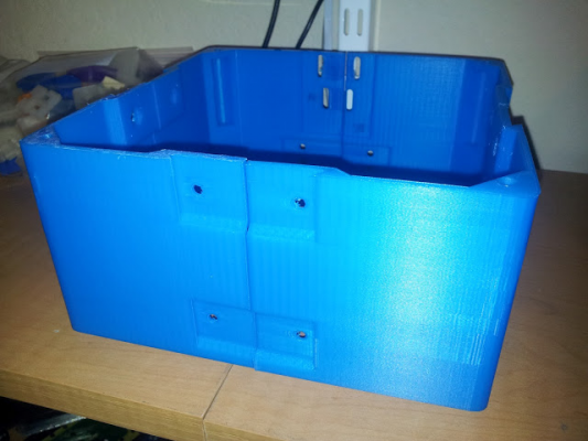
I spent the weekend printing the base pieces. Base_1 was done on hot Kapton since the filament I have doesn't like bare glass. Even then I got some warping at the ends. For Base_2 and Base_3 switched to cold painter's tape. The ends stayed mostly flat, but the corner lifted somewhat. I did Base_4 with painter's tape, but heated the bed to 60 C and used Slic3r 0.8.4 to add a 6mm brim. No warp at all, though I did have to tear up the tape to get it off the bed.
Printing this on a Prusa 2, J-Head mkIV .4mm. Slic3r settings are .27mm layers, 2 perimeters & 2 solid layers, 25% line infill, 55mm/s perimeter and 60mm/s infill. Each piece took a little over 4 hours.
Today contributed to the Indiegogo campaign for the "hardware kit". Also ordered four motors, Sanyo-Denki 103H5208 from Tony of eBay, just like I've been using on my Prusa. These have 4mm shafts and a hard to remove pulley, but are solid performers. Fortunately Sublime has gears for both 4mm and 5mm, and Tony is kind enough to remove the pulleys on request.
Currently printing Middle_1.
|
Re: Pokey's Tantillus build June 26, 2012 12:41AM |
Registered: 13 years ago Posts: 2,947 |
Great color, what brand of PLA is that?
Those are great motors, I have them on a lot of my machines.
Isn't printing on blue tape great? I find stuff sticks a little to well sometimes.
Those are great motors, I have them on a lot of my machines.
Isn't printing on blue tape great? I find stuff sticks a little to well sometimes.
| FFF Settings Calculator | Gcode post processors | Geometric Object Deposition Tool Blog |
| Tantillus.org | Mini Printable Lathe | How NOT to install a Pololu driver |
|
Re: Pokey's Tantillus build June 26, 2012 12:09PM |
Registered: 12 years ago Posts: 195 |
It's Thefutureis3d's blue 3mm PLA. It's kind of translucent, not opaque like Ultimachine's blue. I have a roll of white from them as well, and I'm going to use that for the connectors.
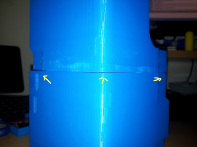
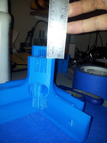
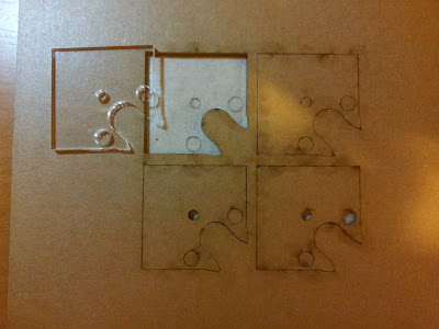
I finished Middle_1 last night using the same process as I did for Base_4 but with a 50C hotbed, and got some lifting at all the corners. The corners of my Middle_1 and Base_1 have some gaps since both had warped (pic). I think my wonky bed is partially to blame. This PLA likes being squashed down hard before it will stick reliably, and I'm finding out that an MDF Y carriage on only three bearings in a humid climate screws up my leveling constantly.
I finished Middle_1 last night using the same process as I did for Base_4 but with a 50C hotbed, and got some lifting at all the corners. The corners of my Middle_1 and Base_1 have some gaps since both had warped (pic). I think my wonky bed is partially to blame. This PLA likes being squashed down hard before it will stick reliably, and I'm finding out that an MDF Y carriage on only three bearings in a humid climate screws up my leveling constantly.
|
Re: Pokey's Tantillus build June 26, 2012 12:43PM |
Registered: 13 years ago Posts: 2,947 |
My finished printed case has some small warping like that too but no one notices it in person and it does not cause any issues.
| FFF Settings Calculator | Gcode post processors | Geometric Object Deposition Tool Blog |
| Tantillus.org | Mini Printable Lathe | How NOT to install a Pololu driver |
|
Re: Pokey's Tantillus build June 30, 2012 11:01AM |
Registered: 12 years ago Posts: 195 |
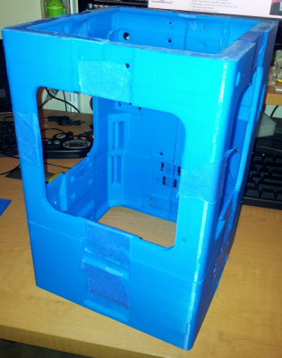
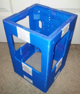
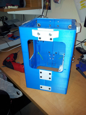
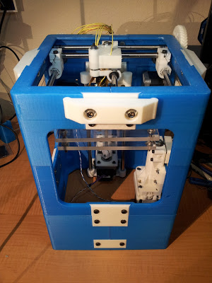
Finally finished the shell. Weight is 572g with a little painter's tape holding it together and before trimming off supports. Time to print was about 55 hours, with all of the base and top and mid-back pieces taking 4.5-5.5 hours each and the mid front pieces taking 2.5.
I had a few setbacks along the way. First, a blob in the filament, what looks to be a splice, took out the outer perimeter on one layer of Top_1. The inner perimeter is intact, and with 25% infill I think it should be ok. I'm saving some blue filament in case it does break though.
Second failure involved the hotend catching on a curled up overhang from one of the bearing holes on Top_2, pushing the glass over a couple of mm and skewing the rest of the print. I turned on support and haven't had trouble again. Again, I attribute this to cheap filament and a really humid environment.
With all that squared away, a BSOD took out the top 15mm of Top_3. This was the only BSOD I've had on this PC since I installed Win7 over two years ago. Go figure. Paranoid, I wired up an SD card reader to my Sanguinololu and built SD support into Marlin.
I'll get started on connectors later today once I decide what color to do the rest in and get them aligned for print.
Edited 4 time(s). Last edit at 06/30/2012 03:04PM by pokey9000.
|
Re: Pokey's Tantillus build July 11, 2012 11:47PM |
Registered: 12 years ago Posts: 195 |
Quick update: Finished the case and connectors. I switched to a cold bed with the blue tape for the connectors. Learned that The Brim is good for sticking parts down but tearing it off may pull off the first couple of layers. I had some additional leveling issues from a slipping Z coupler, so some parts got stuck hard to the blue tape. Almost all the parts have some blue on the back. Fortunately all of the bottoms of the connectors face inwards so it's not a big deal.
I moved back to printing on hot Kapton after switching to an aluminum bed and fixing my Z coupler. I also discovered that this particular plastic (which I suspect is sourced from the same place as Repraper.com) sticks much better when the Kapton is cleaned with acetone instead of ammonia glass cleaner or rubbing alcohol. Now I can print all day long without leveling. Simple joys.
Printed the carriage top and bottom, and the endstop holder. The hotend holes in the carriage came out oval, with about an extra .3mm in the Z direction and .3 less in the X. I suspect Slic3r 0.8.4 may be the culprit.
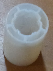
Also printed the LM8UUs with a bunch of false starts. For future reference: Triffid_hunter's PLA bushings are meant to be generated from the SCAD with values derived from your particular slicer. After grabbing the new flow Slic3r branch, rebuilt these using the correct settings. I could never get Slic3r to add more than one perimeter though, so these look a little thin. However, they slide nicely and actually feel pretty durable. The walls measure around 0.6mm. I figure if these don't work, I can shell out for some Igus bushings.
|
Re: Pokey's Tantillus build July 12, 2012 03:07AM |
Registered: 13 years ago Posts: 2,947 |
Looks good.
The bushing look just right. You want them flexible so they don't bind and they don't need to be really strong because they are fully enclosed in the XY ends.
The bushing look just right. You want them flexible so they don't bind and they don't need to be really strong because they are fully enclosed in the XY ends.
| FFF Settings Calculator | Gcode post processors | Geometric Object Deposition Tool Blog |
| Tantillus.org | Mini Printable Lathe | How NOT to install a Pololu driver |
|
Re: Pokey's Tantillus build July 31, 2012 01:24AM |
Registered: 12 years ago Posts: 195 |
I finished with the printed parts last week. Robots-Dreams comic is spot on. By the time I was done with all of this I'd replaced my bed, Y bearing holders, Y rod clamps, cooling fan, and Z couplers just to get consistent prints.
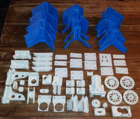
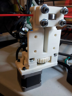
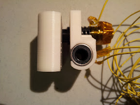
I printed the case as above (25% @ .27mm), extruder at 90% and .20mm, gears and idler holder solid at .18mm (had to play with extrusion width to get the teeth filled well), and everything else 40% hex fill at .20mm. Everything came out ok except for a gap in the wall of the extruder top bearing holder. The gap isn't big and the walls thick enough that it should be ok, and since it took 5 hours to print I'll just redo it if it ever cracks. I did attempt the herringbone extruder gears, and while the teeth exterior perimeters printed cleanly I couldn't get the teeth to infill well, leading to the recommended "v2" gears you see in the picture.
Final weights:
Panels - 564g
Connectors and stiffeners - 128g
Extruder and gears - 124g
XY axis parts - 68g
XY gears - 70g
Z parts - 128g
fan holders and ducts - 30g
So 692g in printed case specific parts, 420g in other parts. Total: 1.112kg in plastic. It was a learning experience printing the case, and it'll be cool having a mostly printed printer.
Meanwhile I've got a Sanguinololu built up and tested, Pololus on the way, and am waiting for .35mm J-Heads to be in stock again.
|
Re: Pokey's Tantillus build July 31, 2012 01:01PM |
Registered: 12 years ago Posts: 99 |
Awesome job! The case is a tough print indeed...glad you were able to get it done!
[johnbiehler.com]
[johnbiehler.com]
|
Re: Pokey's Tantillus build August 02, 2012 10:45PM |
Registered: 13 years ago Posts: 2,947 |
pokey9000 Wrote:
-------------------------------------------------------
> I finished with the printed parts last week.
> Robots-Dreams comic is spot on. By the time I was
> done with all of this I'd replaced my bed, Y
> bearing holders, Y rod clamps, cooling fan, and Z
> couplers just to get consistent prints.
Yeah, I don't exactly design for ease of printing all the time. I would rather get what I want even if it means only being able to be printed by the best tuned machines.
Your prints look great, are you waiting for a hardware kit from me?
| FFF Settings Calculator | Gcode post processors | Geometric Object Deposition Tool Blog |
| Tantillus.org | Mini Printable Lathe | How NOT to install a Pololu driver |
|
Re: Pokey's Tantillus build August 03, 2012 11:48AM |
Registered: 12 years ago Posts: 195 |
Sublime Wrote:
> Yeah, I don't exactly design for ease of printing
> all the time. I would rather get what I want even
> if it means only being able to be printed by the
> best tuned machines.
>
I wouldn't consider any of these parts too difficult for anyone that can manage to successfully print a Wade's extruder and gears. It was a big time commitment though. The only thing that could be done in the design to make it easier would be to add some sort of support to the bearing holes to keep overhangs from curling.
> Your prints look great, are you waiting for a
> hardware kit from me?
Thanks! Yes, I did order a kit, and am all paid up for shipping.
|
Re: Pokey's Tantillus build August 14, 2012 12:25PM |
Registered: 12 years ago Posts: 195 |
Kit received. I made the mistake of not specifying that I was building a printed Tantillus, and so Sublime shipped a laser cut hardware kit. He offered to ship me the missing bits, but as it's my fault and I'm impatient I wound up getting the bits from a local shop. BTW if you are in Austin and need any metric or SAE hardware, Austin Bolt Company off of Metric & Rutland will have anything you might need and will sell exact quantities. They were out of 3/4" plain steel hardware, so I have a mix of stainless 3/4" and plain black 1/4" screws. I need to go back there later for some other sutff and may buy some stainless 1/4" as I like how it looks better.
To get the XY mechanism to fit in a printed case I'll also have to Dremel off a bit at each end of some of the rods, which I'll do sometime later. I'm waiting to get a lasered carriage middle piece from Ponoko before I'll start on the XY.
I started by assembling the extruder. Everything went together well, though I did throw a bolt in between the bearing and big gear as there was some slop lengthwise in the hobbed bolt. Surely the hob would draw the bolt to the right spot if I left it alone, but with the washer the center of the hob lines up exactly. Video of the extruder running
So after getting the printed case hardware from the BOM I started fitting things together. I managed to break both mid front pieces (mid3 and mid4), splitting the connector mount on one and snapping the vertical piece on the other. I think this is a result of printing 2 perimeters with reduced nozzle size to fix Slic3r 0.8.4's screwy flow rate. I anticipate other parts breaking, though the top parts feel solid enough. The top pieces fit together ok, though the back 2 pieces are about 0.5mm out of alignment no matter how many times I try to fit them together. These may need to be reprinted if the rods don't seem true once I install them.
The BOM doesn't mention that the top stiffeners need something longer than 3/4", or that washers are needed. I'll be buying some of these later. When I'm done I'll tally the parts used and post any differences from the BOM.
I'm also unclear on how the vertical supports are meant to be joined. I'm assuming the extra #10-32 x 3/4" hardware is used here, though there is almost no clearance for washers or to hold on to the nuts to tighten them. Right now zip ties are holding it together.
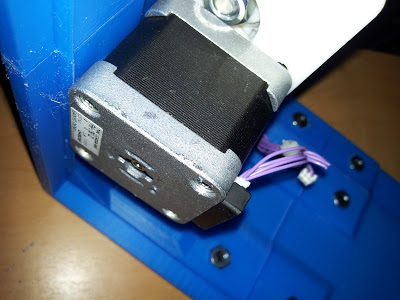
The extruder fits ok, though angled bottom edge of the case pushes on the side of the motor, skewing the extruder a tiny bit. I'll shave this down at some point.
Edited 2 time(s). Last edit at 08/14/2012 12:33PM by pokey9000.
|
Re: Pokey's Tantillus build August 14, 2012 02:57PM |
Registered: 13 years ago Posts: 2,947 |
pokey9000 Wrote:
-------------------------------------------------------
> I started by assembling the extruder. Everything
> went together well, though I did throw a bolt in
> between the bearing and big gear as there was some
> slop lengthwise in the hobbed bolt. Surely the
> hob would draw the bolt to the right spot if I
> left it alone, but with the washer the center of
> the hob lines up exactly. Video of the extruder
> running
Yes I have supplied an extra washer for the extruder in case the hobbed bolt does not line up correctly but forgot to mention it in the instructions (adding).
> So after getting the printed case hardware from
> the BOM I started fitting things together. I
> managed to break both mid front pieces (mid3 and
> mid4), splitting the connector mount on one and
> snapping the vertical piece on the other. I think
> this is a result of printing 2 perimeters with
> reduced nozzle size to fix Slic3r 0.8.4's screwy
> flow rate. I anticipate other parts breaking,
> though the top parts feel solid enough. The top
> pieces fit together ok, though the back 2 pieces
> are about 0.5mm out of alignment no matter how
> many times I try to fit them together. These may
> need to be reprinted if the rods don't seem true
> once I install them.
0.8.4 does not have anything wrong with the flow rate it actually calculates the perimeter location wrong and makes everything 0.1mm larger on X and Y. This is enough to make all the parts not fit together as intended.
>
> The BOM doesn't mention that the top stiffeners
> need something longer than 3/4", or that washers
> are needed. I'll be buying some of these later.
> When I'm done I'll tally the parts used and post
> any differences from the BOM.
3/4" is the correct length but you are right that I forgot the washers for those.
> I'm also unclear on how the vertical supports are
> meant to be joined. I'm assuming the extra #10-32
> x 3/4" hardware is used here, though there is
> almost no clearance for washers or to hold on to
> the nuts to tighten them. Right now zip ties are
> holding it together.
Again I did not think of those. They are not really needed because the other connectors join it together. The corner ones were from the very first prototype that I tried to print in 3 pieces instead of 12. If you wold like to install some bolts there you can use #8 x 1" I believe.
>
> The extruder fits ok, though angled bottom edge of
> the case pushes on the side of the motor, skewing
> the extruder a tiny bit. I'll shave this down at
> some point.
This is probably a result of the case being curved in in the middle and 0.8.4 making everything to large. Although it is designed to have the motor touch (zero clearance).
| FFF Settings Calculator | Gcode post processors | Geometric Object Deposition Tool Blog |
| Tantillus.org | Mini Printable Lathe | How NOT to install a Pololu driver |
|
Re: Pokey's Tantillus build August 14, 2012 05:16PM |
Registered: 12 years ago Posts: 195 |
Sublime Wrote:
-------------------------------------------------------
>
> 0.8.4 does not have anything wrong with the flow
> rate it actually calculates the perimeter location
> wrong and makes everything 0.1mm larger on X and
> Y. This is enough to make all the parts not fit
> together as intended.
I should have been a little more clear. My Prusa uses a MkIV J-Head so I had to use an artificially low nozzle width to avoid unnecessary blobbing. So my perimeter walls are thin. I thought that 0.8.4 had an issue with inner perimeters (holes) but outer perimeters wound up ok. I used 0.8.4 for the case and connectors, but after having trouble with the printed bushings I started building my own Slic3r from Github. This was after the new-flow-rate commits and the perimeter fixes. I might need to reprint the case but the rest of the parts should be ok. Which is good as I'm running low on blue and white...
> 3/4" is the correct length but you are right that
> I forgot the washers for those.
Are we supposed to tighten these down until the back is flush with the case side? If so then 3/4" should fit and I can save a trip to the bolt shop.
> > The extruder fits ok, though angled bottom edge
> of
> > the case pushes on the side of the motor,
> skewing
> > the extruder a tiny bit. I'll shave this down
> at
> > some point.
>
> This is probably a result of the case being curved
> in in the middle and 0.8.4 making everything to
> large. Although it is designed to have the motor
> touch (zero clearance).
Ok, I'll see how it goes when I reprint the case.
Out of curiosity, where do you mount the electronics on your printed case printer? I was thinking about putting my Sanguinololu on the outside back just under the Bowden tube.
|
Re: Pokey's Tantillus build August 14, 2012 05:25PM |
Registered: 13 years ago Posts: 2,947 |
pokey9000 Wrote:
-------------------------------------------------------
> Sublime Wrote:
> --------------------------------------------------
> -----
> >
> > 0.8.4 does not have anything wrong with the
> flow
> > rate it actually calculates the perimeter
> location
> > wrong and makes everything 0.1mm larger on X
> and
> > Y. This is enough to make all the parts not fit
> > together as intended.
>
> I should have been a little more clear. My Prusa
> uses a MkIV J-Head so I had to use an artificially
> low nozzle width to avoid unnecessary blobbing.
> So my perimeter walls are thin. I thought that
> 0.8.4 had an issue with inner perimeters (holes)
> but outer perimeters wound up ok. I used 0.8.4
> for the case and connectors, but after having
> trouble with the printed bushings I started
> building my own Slic3r from Github. This was
> after the new-flow-rate commits and the perimeter
> fixes. I might need to reprint the case but the
> rest of the parts should be ok. Which is good as
> I'm running low on blue and white...
Actually 0.8.4 had really serious bugs and he left it on his homepage as a stable release even though it should have been deleted and never looked at again. It has caused most of the problems you read about on the RepRap forums regarding Slic3r in the past month.
>
> > 3/4" is the correct length but you are right
> that
> > I forgot the washers for those.
>
> Are we supposed to tighten these down until the
> back is flush with the case side? If so then 3/4"
> should fit and I can save a trip to the bolt
> shop.
I have one washer under the bolt head in the stiffener and one behind the stiffener between it and the case. The idea is that you can adjust how much force is applied to the case by moving the washers from behind the stiffener to under the bolt head while keeping the end of the bolt from sticking through inside the case. All of this needs to be documented better but I have my hands full with the laser cut case instructions. I and other would greatly appreciate it if you could add this info to the Wiki page.
>
> > > The extruder fits ok, though angled bottom
> edge
> > of
> > > the case pushes on the side of the motor,
> > skewing
> > > the extruder a tiny bit. I'll shave this
> down
> > at
> > > some point.
> >
> > This is probably a result of the case being
> curved
> > in in the middle and 0.8.4 making everything to
> > large. Although it is designed to have the
> motor
> > touch (zero clearance).
>
> Ok, I'll see how it goes when I reprint the case.
I would not bother to reprint the case unless it is unusable in the current state.
> Out of curiosity, where do you mount the
> electronics on your printed case printer? I was
> thinking about putting my Sanguinololu on the
> outside back just under the Bowden tube.
The printed case has lip in the bottom you can screw a bottom cover to. I then screwed the electronics to this bottom cover. The bottom cover also helps to stiffen the case further.
| FFF Settings Calculator | Gcode post processors | Geometric Object Deposition Tool Blog |
| Tantillus.org | Mini Printable Lathe | How NOT to install a Pololu driver |
|
Re: Pokey's Tantillus build August 15, 2012 12:36PM |
Registered: 12 years ago Posts: 195 |
Sublime Wrote:
-------------------------------------------------------
> pokey9000 Wrote:
> --------------------------------------------------
> -----
> Actually 0.8.4 had really serious bugs and he left
> it on his homepage as a stable release even though
> it should have been deleted and never looked at
> again. It has caused most of the problems you read
> about on the RepRap forums regarding Slic3r in the
> past month.
0.9.1 is working fine for me at the moment, though I still can't seem to print the carriage such that the tops of the bearings are exposed. I've seen in some of the other threads that I'm not alone, though in my case the bearings fit snugly. I'm also finding that the hotend groove sits just below the surface so the carriage mid piece wouldn't hold it. It's as if shaving off a bit from the middle facing side of each piece would result in parts that match your photos.
The top rear pieces seem to be a bust for me. They look fine but when I fit everything together there's a significant gap between the top and middle pieces that follows the unevenness I noticed in the top edge. The weird thing is that everything measures ok: it's 97.5mm top to bottom all the way across on both pieces and the nuts sit in the same line on both and at the same distance from the edge. When I fit one of the pieces at a time to the rest of the case all looks ok, but when I install both but It seems like Slic3r may still be to blame, though I did have some issues with lower Y bed warping problems when I was printing the case.
>
> I have one washer under the bolt head in the
> stiffener and one behind the stiffener between it
> and the case. The idea is that you can adjust how
> much force is applied to the case by moving the
> washers from behind the stiffener to under the
> bolt head while keeping the end of the bolt from
> sticking through inside the case. All of this
> needs to be documented better but I have my hands
> full with the laser cut case instructions. I and
> other would greatly appreciate it if you could add
> this info to the Wiki page.
I see that I was beaten to the punch. I'll try to get a photo of one of mine attached to the article.
>
> >
> > > > The extruder fits ok, though angled bottom
> > edge
> > > of
> > > > the case pushes on the side of the motor,
> > > skewing
> > > > the extruder a tiny bit. I'll shave this
> > down
> > > at
> > > > some point.
> > >
> > > This is probably a result of the case being
> > curved
> > > in in the middle and 0.8.4 making everything
> to
> > > large. Although it is designed to have the
> > motor
> > > touch (zero clearance).
...
> > Out of curiosity, where do you mount the
> > electronics on your printed case printer?
>
> The printed case has lip in the bottom you can
> screw a bottom cover to. I then screwed the
> electronics to this bottom cover. The bottom cover
> also helps to stiffen the case further.
I didn't even notice that! Since the corners are square it should be a piece of cake to put a piece of plywood down there. That also solves how to get USB and power in and out: I'll put rubber feet on the bottom and cut some notches for cables to snake through.
That lip is what my motor is running into. My motor is 39mm long and sticks out another 3mm or so below: Is this the edge the motor is supposed to be flush with?
Thanks for all your help on this. I know you're pretty busy right now, so I'll try to update the wiki with anything I learn here.
Edited 1 time(s). Last edit at 08/15/2012 12:38PM by pokey9000.
|
Re: Pokey's Tantillus build August 15, 2012 05:18PM |
Registered: 13 years ago Posts: 2,947 |
pokey9000 Wrote:
-------------------------------------------------------
> 0.9.1 is working fine for me at the moment, though
> I still can't seem to print the carriage such that
> the tops of the bearings are exposed. I've seen
> in some of the other threads that I'm not alone,
> though in my case the bearings fit snugly. I'm
> also finding that the hotend groove sits just
> below the surface so the carriage mid piece
> wouldn't hold it. It's as if shaving off a bit
> from the middle facing side of each piece would
> result in parts that match your photos.
I use 0.7.2 and it does not print the ends of the sharp points are part of the object. Instead it prints the points seperately and they then come off with your fingers and do not cause this problem with the bearings not touching the acrylic. For the rest I am not sure I follow, did you wrap the top of the hotend in Kapton to make it fit tighter in the upper carriage?
>
> The top rear pieces seem to be a bust for me.
> They look fine but when I fit everything together
> there's a significant gap between the top and
> middle pieces that follows the unevenness I
> noticed in the top edge. The weird thing is that
> everything measures ok: it's 97.5mm top to bottom
> all the way across on both pieces and the nuts sit
> in the same line on both and at the same distance
> from the edge. When I fit one of the pieces at a
> time to the rest of the case all looks ok, but
> when I install both but It seems like Slic3r may
> still be to blame, though I did have some issues
> with lower Y bed warping problems when I was
> printing the case.
Can you just scrap the extra material away to make it fit? Have you tried to assemble it all with the bolts loose and then tighten them after all the parts are connected?
> I didn't even notice that! Since the corners are
> square it should be a piece of cake to put a piece
> of plywood down there. That also solves how to
> get USB and power in and out: I'll put rubber feet
> on the bottom and cut some notches for cables to
> snake through.
Exactly.
>
> That lip is what my motor is running into. My
> motor is 39mm long and sticks out another 3mm or
> so below:
Mine motor sits almost flush with the lip. Try loosening the extruder mount bolts and see if yo can move it up a little. The mounting holes in the extruder are oversized to make sure you can get them all to line up on the printed case holes that are not always the same spacing.
>
> Thanks for all your help on this. I know you're
> pretty busy right now, so I'll try to update the
> wiki with anything I learn here.
Thanks that would be great.
| FFF Settings Calculator | Gcode post processors | Geometric Object Deposition Tool Blog |
| Tantillus.org | Mini Printable Lathe | How NOT to install a Pololu driver |
|
Re: Pokey's Tantillus build August 16, 2012 02:43AM |
Registered: 12 years ago Posts: 195 |
Sublime Wrote:
-------------------------------------------------------
> I use 0.7.2 and it does not print the ends of the
> sharp points are part of the object. Instead it
> prints the points seperately and they then come
> off with your fingers and do not cause this
> problem with the bearings not touching the
> acrylic. For the rest I am not sure I follow, did
> you wrap the top of the hotend in Kapton to make
> it fit tighter in the upper carriage?
0.9.1 prints them to points, but they are easily trimmed back. After trimming, the bearings are still a fraction of a mm from being flush with the surface (I'm still waiting to get my middle piece lasered). As for the hotend, maybe I'm misunderstanding how it's meant to stay perpendicular to the XY plane. I get a mostly good fit from the hole dimensions. But I had thought that the carriage middle piece was meant to press upwards on the hotend to keep it level. It's entirely possible I'm just confused. I'm used to it.
> Can you just scrap the extra material away to make
> it fit? Have you tried to assemble it all with the
> bolts loose and then tighten them after all the
> parts are connected?
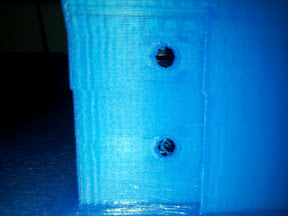
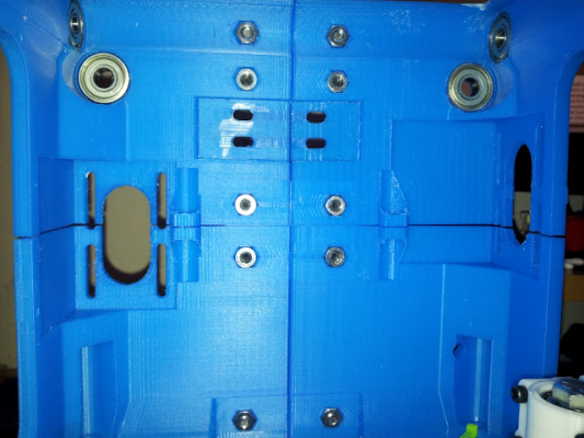
I tried scraping the vertical edge between the afflicted parts with no effect. The warping is linear going horizontally, with the motor mounts being about 1.5mm apart at the corners. Not sure if this is warp or something else. It didn't seem to happen to all the parts as the bottom and the front parts came out ok. The 4 back mid and back top parts are affected. Photo so you can see what I'm talking about:
My printer seems calibrated, with 20mm cube prints coming out dimensionally correct. However, both Slic3r 0.9.1 and 0.7.2b slice the 100x100 pieces to 99.5mm, with prints coming out closer to 99mm. Could this be related to my problem?
Feel free to tell me I'm being too paranoid here.
> > That lip is what my motor is running into. My
> > motor is 39mm long and sticks out another 3mm
> or
> > so below:
>
> Mine motor sits almost flush with the lip. Try
> loosening the extruder mount bolts and see if yo
> can move it up a little. The mounting holes in the
> extruder are oversized to make sure you can get
> them all to line up on the printed case holes that
> are not always the same spacing.
At least I was able to get one thing fixed today. I had a hard time trying to move the motor around side-to-side. That's when I noticed that the laser cut kit ships with 8mm OD M3 washers, and there's barely enough clearance around the motor mount holes for them to fit. I switched to some 7mm OD washers and I was able to get the motor to just barely touch. Wiki is updated with a description of how it's meant to fit.
|
Re: Pokey's Tantillus build August 16, 2012 03:30AM |
Registered: 13 years ago Posts: 2,947 |
pokey9000 Wrote:
-------------------------------------------------------
> 0.9.1 prints them to points, but they are easily
> trimmed back. After trimming, the bearings are
> still a fraction of a mm from being flush with the
> surface (I'm still waiting to get my middle piece
> lasered).
This fraction of an inch is mostly likely the additional material added by 0.8.4 if these were printed with it like the rest of the parts.
As for the hotend, maybe I'm
> misunderstanding how it's meant to stay
> perpendicular to the XY plane. I get a mostly
> good fit from the hole dimensions. But I had
> thought that the carriage middle piece was meant
> to press upwards on the hotend to keep it level.
> It's entirely possible I'm just confused. I'm
> used to it.
I am still not sure I follow. A picture would help. Once you get the laser cut part (which you could print temporarily) I am sure it will make more sense.
> I tried scraping the vertical edge between the
> afflicted parts with no effect. The warping is
> linear going horizontally, with the motor mounts
> being about 1.5mm apart at the corners. Not sure
> if this is warp or something else. It didn't seem
> to happen to all the parts as the bottom and the
> front parts came out ok. The 4 back mid and back
> top parts are affected. Photo so you can see what
> I'm talking about:
> My printer seems calibrated, with 20mm cube prints
> coming out dimensionally correct. However, both
> Slic3r 0.9.1 and 0.7.2b slice the 100x100 pieces
> to 99.5mm, with prints coming out closer to 99mm.
> Could this be related to my problem?
They are not actually 100mm. I don't think it would cause the problem.
> Feel free to tell me I'm being too paranoid here.
I would use it, the motors are going to connect the parts together.
> At least I was able to get one thing fixed today.
> I had a hard time trying to move the motor around
> side-to-side. That's when I noticed that the
> laser cut kit ships with 8mm OD M3 washers, and
> there's barely enough clearance around the motor
> mount holes for them to fit. I switched to some
> 7mm OD washers and I was able to get the motor to
> just barely touch. Wiki is updated with a
> description of how it's meant to fit.
I had not tried the new mount with the washer recesses on the printed case. The original had thinner walls and more room for the washers but was not as strong and the sides were not always printed in a continuous perimeter.
| FFF Settings Calculator | Gcode post processors | Geometric Object Deposition Tool Blog |
| Tantillus.org | Mini Printable Lathe | How NOT to install a Pololu driver |
|
Re: Pokey's Tantillus build August 21, 2012 01:40AM |
Registered: 12 years ago Posts: 195 |
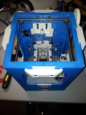
The progress so far:
Z axis is built, but needs to come off at some point to cut clearance for the X and Y motors from the bed, install longer bed bolts, and to file out the Z arm holes on the short edge to allow for a little play along the X axis. When I filed them to fit I only did enough such that the Z lift fits snugly.
Finally got the 5/16" rods cut to the printed case. That stuff takes a long time to Dremel.
Just a sanity check: when fit correctly, the holes in the 220mm 5/16" rods should be aligned with the outside edge of the rods on the orthogonal axis, right? I found that I needed to take 8mm off the end that slides in the case first in order for the holes to be spaced evenly. My X axis rod now looks like this:
Left to do:
-Cut/crimp/assemble hotend and hotend cabling
-Cut/solder/crimp harnesses for motors and endstop
-Z axis fixup: Cut bed clearance, replace bed screws, file Z arm holes
-Hook up Bowden
-Assemble XY axis - waiting on carriage mid to come in from Ponoko
-Mount motors and attach gears
-Mount fans
-Temporary electronics mount under the case- cardboard or foamcore board until I can borrow time on a table saw
-Install electronics - load Tantillus Marlin. memo to self: turn off SD and front panel support & select Sanguinololu
|
Re: Pokey's Tantillus build August 21, 2012 02:44AM |
Registered: 11 years ago Posts: 149 |
Looking pretty nice there Pokey, I dig the color scheme 
I believe a snug fit on both the long and short edges of the Z-arm holes is what you want. Sublime will probably give the correct answer to this - I'd hold off on the filing till he does.
Not sure if there's a difference with the printed case, but my cable holes are each about 12mm from the inside surface of my corner connectors(no corner connectors on the printed case though, so not sure if this is a good reference). This makes my holes line up approximately with the center of the orthogonal rods, rather than the outside edge like you suggested. The cables holes definitely should be evenly spaced, but it seems strange to me that you'd have to cut off 8mm to get even spacing.
|
Re: Pokey's Tantillus build August 22, 2012 12:53AM |
Registered: 13 years ago Posts: 2,947 |
I believe Pokey needed to cut the ends because he got a laser cut hardware kit and it has longer rods then the printed one uses. The holes do need to be centered, Pokey you ended up doing it correct. The space from the hole to the outside though is much less on the printed case than on the laser cut one. The laser cut case almost fits over the printed one because the laser cut case does not have the recesses that the printed case does for the extruder gear and the Z brackets.
| FFF Settings Calculator | Gcode post processors | Geometric Object Deposition Tool Blog |
| Tantillus.org | Mini Printable Lathe | How NOT to install a Pololu driver |
|
Re: Pokey's Tantillus build August 28, 2012 02:11AM |
Registered: 12 years ago Posts: 195 |
I've been slowly working through my checklist the last few days. Motor harnesses are made and tested, endstop is wired and tested, clearances cut in the bed for the motors, bed bolts replaced with 1.5" cap screws. I bought a "chocolate bar" terminal block for the hotend as the Sanguinololu terminates wiring in KK crimp connectors and not screw terminals like RAMPS. If I crimped a connector to the end of the wiring I'd never be able to extract the hotend without cutting wires. Still not sure how I'll run the hotend wiring, but I imagine feeding it through the corner of the right window near the extruder, and hot gluing the terminal block there.
For anyone wondering, the hotend is put together similarly to the MkIV J-Head on my Prusa: 22ga wiring for both the thermistor and the heater, bootlace crimp ferrules + solder, Kapton insulating everything with a generous amount around the brass block. The 22ga wire is good to 80C, which has proven enough for my Prusa, and the solder and ferrule combo maintains a good connection even if the junction goes above the melting temp. Unlike on my Prusa, this J-Head came with the 5.6 ohm resistor which has an even surface and fit very snugly in the bore. On my Prusa's MkIV, which came with a 6.8 ohm resistor, I had to use muffler cement to hold it in as that model resistor has an uneven surface and is smaller than the bore.
Ok, I freely admit I was paranoid about how the carriage came out. I trimmed off Slic3r's attempt at printing the thin bits around the bearing and the bearings are perfectly flush with the surface of the top and bottom. Tomorrow UPS is supposed to drop off the laser cut carriage mid pieces. I'm anxious to see how it fits...
I spent a few minutes at work looking at the Tantillus Marlin branch, and (correct me if I'm wrong) just about all of the changes that pertain to a setup without the LCD UI and SD card are in the configuration.h and configuration_adv.h files. I will be using a Sanguinololu without the LCD panel or SD card. I'll stick with this branch, as AFAIK the only changes needed are to disable the UI and SD, select Sanguinololu, and put the fan control on the heated bed PWM channel.
|
Re: Pokey's Tantillus build August 28, 2012 02:33AM |
Registered: 13 years ago Posts: 2,947 |
Yeah most of the changes do revolve around the LCD . But some will help with use via USB as well. The easy LOAD function allows you to load and unload long lengths without disabling long extrusion prevention entirely. The Auto min fan feature ensures there is always air blowing across the thermal barrier on the J-head. There are some new M codes to control lighting that could possibly give an error but I think I have them disabled automatically if the pins are not defined.
| FFF Settings Calculator | Gcode post processors | Geometric Object Deposition Tool Blog |
| Tantillus.org | Mini Printable Lathe | How NOT to install a Pololu driver |
|
Re: Pokey's Tantillus build August 31, 2012 12:33PM |
Registered: 12 years ago Posts: 195 |
My laser cut carriage mid pieces came in on Tuesday, and I've been busy since...
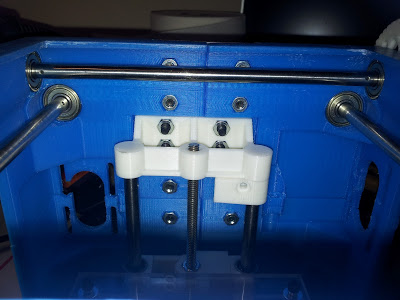
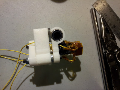
The carriage mid is a little loose on the J-Head as-is, but a couple of Kapton pieces like in the directions and it's nice and snug. Here's the carriage before installation:
My first attempt at stringing up the carriage ended in a cracked right X end. I've been using a ratcheting screwdriver with some SAE hex bits for this project and torqued a little too much when tightening. I need to get a set of proper wrenches to complement all my metric tools. Yes, that's right, a Texan with more metric tools than SAE. Fortunately I hadn't installed the other lines yet.
I spent the last two days reprinting the ends and stringing it all up again. Running the line on the printed case is really tedious! For anyone that goes this route, get some tweezers and a bright directional lamp.
I'm having a hard time getting the X axis square (the Y is spot on). I think it's due to not getting the lines tensioned well enough, as I've been using a hex bit in an extension to hand tighten the ends. Also, now that I think about it, I have been putting the washers smooth side towards the ends, figuring that the sharp edges on the other side might damage the line, and maybe I'd have better luck with the sharp side.
BTW it was marginally more to laser cut 4 carriage mid pieces than to cut one, so I have 3 spares. This is the only piece not included in the printed case HW kit that's hard to make without special tools. So if anyone within the US wants one, PM me with a pic of your built-up case (to make sure you're committed to building one) and your address and I'll send you a carriage mid piece.
|
Re: Pokey's Tantillus build August 31, 2012 12:56PM |
Registered: 11 years ago Posts: 149 |
pokey9000 Wrote:
-------------------------------------------------------
> Yes,
> that's right, a Texan with more metric tools than
> SAE. Fortunately I hadn't installed the other
> lines yet.
LOL nice one... made me laugh a lot harder than it should have You must be in Austin?
> I'm having a hard time getting the X axis square
> (the Y is spot on). I think it's due to not
> getting the lines tensioned well enough, as I've
> been using a hex bit in an extension to hand
> tighten the ends. Also, now that I think about
> it, I have been putting the washers smooth side
> towards the ends, figuring that the sharp edges on
> the other side might damage the line, and maybe
> I'd have better luck with the sharp side.
I'd say keep the smooth side of the washer on the side that touches the line as Sublime suggests - I had one in the wrong direction and it cost me a couple hours of tear-down and rebuilding after the line got cut from the sharp side. I don't think flipping the washer would make a difference in terms of keeping the line taught once the screw is clamped down.
-------------------------------------------------------
> Yes,
> that's right, a Texan with more metric tools than
> SAE. Fortunately I hadn't installed the other
> lines yet.
LOL nice one... made me laugh a lot harder than it should have
 You must be in Austin?
> I'm having a hard time getting the X axis square
> (the Y is spot on). I think it's due to not
> getting the lines tensioned well enough, as I've
> been using a hex bit in an extension to hand
> tighten the ends. Also, now that I think about
> it, I have been putting the washers smooth side
> towards the ends, figuring that the sharp edges on
> the other side might damage the line, and maybe
> I'd have better luck with the sharp side.
I'd say keep the smooth side of the washer on the side that touches the line as Sublime suggests - I had one in the wrong direction and it cost me a couple hours of tear-down and rebuilding after the line got cut from the sharp side. I don't think flipping the washer would make a difference in terms of keeping the line taught once the screw is clamped down.
|
Re: Pokey's Tantillus build August 31, 2012 03:33PM |
Registered: 13 years ago Posts: 2,947 |
Nice work Pokey,
The cables are much more difficult to install on the printed machine then on the laser cut one, and they are not that easy to install on the laser cut one.
To get them square is actually not that hard but it needs a video to explain it. I will try and get one up over the weekend so people can see what I was trying to say in the instructions.
A few people have broken the XYends so I will be having a go at making them stronger while not taking up any more space in the printed case.
| FFF Settings Calculator | Gcode post processors | Geometric Object Deposition Tool Blog |
| Tantillus.org | Mini Printable Lathe | How NOT to install a Pololu driver |
|
Re: Pokey's Tantillus build August 31, 2012 04:24PM |
Registered: 12 years ago Posts: 195 |
Thanks Sublime. I'll focus on something else for the time being.
If you're redesigning the XY ends, consider a little more clearance in the slots for the zip ties. I cracked the thin outer shell on the one I just reprinted using some zip ties I had as opposed to the ones you sent. These ties are the same dimensions except for being a little thicker. The shell doesn't look to have any structural function so I'm not going to bother fixing it.
Also, I had clearance problems with the zip tie head on the right X-end such that it was rubbing against the case when the Y slides towards the back. I trimmed a mm or two off with diagonal cutters and it's fine, but I was wondering if there was a better orientation for the tie at least on that side.
As far as the cables, finding an alternate way to wind the 5 turns of cable between the holes and the bearings would save a ton of time. Something along the lines of winding towards the center of the rod first with 10 turns each, pulling the cable taut through the nearest window, then turning the gear 5 turns in the opposite direction while guiding the cable.
|
Re: Pokey's Tantillus build August 31, 2012 04:35PM |
Registered: 13 years ago Posts: 2,947 |
pokey9000 Wrote:
-------------------------------------------------------
> Thanks Sublime. I'll focus on something else for
> the time being.
>
> If you're redesigning the XY ends, consider a
> little more clearance in the slots for the zip
> ties. I cracked the thin outer shell on the one I
> just reprinted using some zip ties I had as
> opposed to the ones you sent. These ties are the
> same dimensions except for being a little thicker.
> The shell doesn't look to have any structural
> function so I'm not going to bother fixing it.
I have found you can remove the entire thin section in the middle of the XYend without it causing any problems. In fact it actually holds the bushing a little better with it removed. Increasing the slot will not be an issue and I will do so when I modify them.
>
> Also, I had clearance problems with the zip tie
> head on the right X-end such that it was rubbing
> against the case when the Y slides towards the
> back. I trimmed a mm or two off with diagonal
> cutters and it's fine, but I was wondering if
> there was a better orientation for the tie at
> least on that side.
Yeah the printed case is short on space and everything is crammed in there very tightly. You can try installing it at the same end as before but on the inside, just watch that it does not hit the carriage. You can also remove the zip tie if the bushing fits tightly enough (I have two machine without zip ties).
>
> As far as the cables, finding an alternate way to
> wind the 5 turns of cable between the holes and
> the bearings would save a ton of time. Something
> along the lines of winding towards the center of
> the rod first with 10 turns each, pulling the
> cable taut through the nearest window, then
> turning the gear 5 turns in the opposite direction
> while guiding the cable.
This does make sense and as long as you do both at the same time it should work well. Although it could be more frustrating to do both at once than one at a time.
| FFF Settings Calculator | Gcode post processors | Geometric Object Deposition Tool Blog |
| Tantillus.org | Mini Printable Lathe | How NOT to install a Pololu driver |
|
Re: Pokey's Tantillus build August 31, 2012 06:17PM |
Registered: 11 years ago Posts: 116 |
> A few people have broken the XYends so I will be
> having a go at making them stronger while not
> taking up any more space in the printed case.
Yup... broke another one today.
I now need to pull it all apart again ...and I guess find more fishing line somewhere. Least favorite movie "Ground Hog Day". ...but practice makes perfect ...I guess. I really really really just want to print something and my time to work on this has all but disappeared as my work season starts up again.
> having a go at making them stronger while not
> taking up any more space in the printed case.
Yup... broke another one today.

I now need to pull it all apart again ...and I guess find more fishing line somewhere. Least favorite movie "Ground Hog Day". ...but practice makes perfect ...I guess. I really really really just want to print something and my time to work on this has all but disappeared as my work season starts up again.
Sorry, only registered users may post in this forum.
