Pokey's Tantillus build
Posted by pokey9000
|
Re: Pokey's Tantillus build August 31, 2012 06:29PM |
Registered: 13 years ago Posts: 2,947 |
Lisa M Wrote:
-------------------------------------------------------
> Yup... broke another one today.
>
> I now need to pull it all apart again ...and I
> guess find more fishing line somewhere. Least
> favorite movie "Ground Hog Day". ...but practice
> makes perfect ...I guess. I really really really
> just want to print something and my time to work
> on this has all but disappeared as my work season
> starts up again.
If you are coming out to Abby again I can get you some more Spectra cable. If not you can get it from Canadian tire and sporting goods places that sell fishing supplies. Just be sure to get 65lb. Also this time replace all the original XYends with the ones I gave you. Obviously there was something wrong with the original set.
| FFF Settings Calculator | Gcode post processors | Geometric Object Deposition Tool Blog |
| Tantillus.org | Mini Printable Lathe | How NOT to install a Pololu driver |
|
Re: Pokey's Tantillus build August 31, 2012 06:33PM |
Registered: 11 years ago Posts: 95 |
Hi Lisa,
Bummer to hear you broke another.
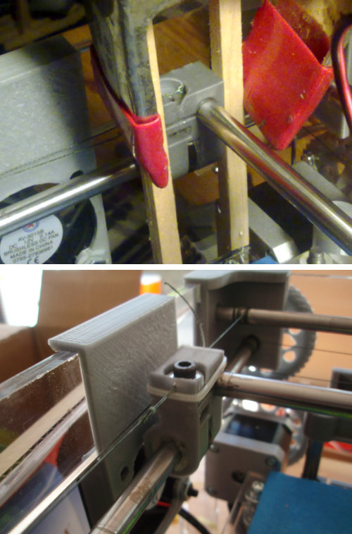
Just in case you'd care to try the fix I did on my broken end, I've attached a picture. I did the regular CA gluing (which didn't hold for long), and then did it again with an added little zip-tie. It's now the end I'm most confident to tighten up. - Just in case you want to give it a go before dismantling your Tantillus
Bummer to hear you broke another.
Just in case you'd care to try the fix I did on my broken end, I've attached a picture. I did the regular CA gluing (which didn't hold for long), and then did it again with an added little zip-tie. It's now the end I'm most confident to tighten up. - Just in case you want to give it a go before dismantling your Tantillus
|
Re: Pokey's Tantillus build August 31, 2012 07:49PM |
Registered: 11 years ago Posts: 116 |
> If you are coming out to Abby again I can get you
> some more Spectra cable. If not you can get it
> from Canadian tire and sporting goods places that
> sell fishing supplies. Just be sure to get 65lb.
> Also this time replace all the original XYends
> with the ones I gave you. Obviously there was
> something wrong with the original set.
I will need a couple of bushings too.... two of mine were glued in.
|
Re: Pokey's Tantillus build September 12, 2012 11:42AM |
Registered: 12 years ago Posts: 195 |
My Tantillus now moves! Video here. The electronics need to be mounted and there's some cleanup to do, but the hotend gets hot and all the motors move. As you can see the new style XY ends are working great and haven't cracked through a number of tightenings.
I ran into one problem though: the limits of the hotend travel aren't even with the build glass area. At the left corners, the hotend runs into the screws, and on the right there's a considerable gap.
I cut and drilled the platforms from a template made from the laser cut files. This should be identical to the laser cut bed. Is this supposed to be ok to use for the printed case version too?
Also, how are the fan mounts meant to work in the printed case? I assume they replace the washers behind the stiffeners on the left and right top of the case, but the tab isn't long enough to clear the stiffener or bring the fan below the top of the case windows.
Edited 2 time(s). Last edit at 09/12/2012 12:02PM by pokey9000.
I ran into one problem though: the limits of the hotend travel aren't even with the build glass area. At the left corners, the hotend runs into the screws, and on the right there's a considerable gap.


I cut and drilled the platforms from a template made from the laser cut files. This should be identical to the laser cut bed. Is this supposed to be ok to use for the printed case version too?
Also, how are the fan mounts meant to work in the printed case? I assume they replace the washers behind the stiffeners on the left and right top of the case, but the tab isn't long enough to clear the stiffener or bring the fan below the top of the case windows.
Edited 2 time(s). Last edit at 09/12/2012 12:02PM by pokey9000.
|
Re: Pokey's Tantillus build September 12, 2012 01:51PM |
Registered: 13 years ago Posts: 2,947 |
pokey9000 Wrote:
-------------------------------------------------------
> I ran into one problem though: the limits of the
> hotend travel aren't even with the build glass
> area. At the left corners, the hotend runs into
> the screws, and on the right there's a
> considerable gap.
This is most likely because the upper and/or lower Z brackets are not in the center as they should be. Try loosening the upper bolts and sliding the bracket to the left.
> I cut and drilled the platforms from a template
> made from the laser cut files. This should be
> identical to the laser cut bed. Is this supposed
> to be ok to use for the printed case version too?
It should because it uses the same inner geometry and I never moved anything except the case parts.
>
> Also, how are the fan mounts meant to work in the
> printed case? I assume they replace the washers
> behind the stiffeners on the left and right top of
> the case, but the tab isn't long enough to clear
> the stiffener or bring the fan below the top of
> the case windows.
Yes they go behind the stiffener but they face outwards not inwards so the lip does not need to clear the window.
| FFF Settings Calculator | Gcode post processors | Geometric Object Deposition Tool Blog |
| Tantillus.org | Mini Printable Lathe | How NOT to install a Pololu driver |
|
Re: Pokey's Tantillus build September 12, 2012 03:43PM |
Registered: 12 years ago Posts: 195 |
Sublime Wrote:
-------------------------------------------------------
>
> This is most likely because the upper and/or lower
> Z brackets are not in the center as they should
> be. Try loosening the upper bolts and sliding the
> bracket to the left.
The bracket is as far to the left as possible. I just removed both plates and measured them to match the STL that contains them (All_Panels.svg) within <1mm. What I'm seeing is as if the Z axis were shifted to the right ~3mm, but the axis is situated as far left as it will go. Could I have something misplaced or on backwards on the XY?
> Yes they go behind the stiffener but they face
> outwards not inwards so the lip does not need to
> clear the window.
Ok, I see. Even in that orientation the lip doesn't clear the stiffener. From the lip to the center of the hole on the fan holder is 6mm, while it's 10mm from the edge to the hole centers on the stiffeners. I'll see if I can stretch it out and reprint it later.
Thanks
Edited 2 time(s). Last edit at 09/12/2012 03:59PM by pokey9000.
|
Re: Pokey's Tantillus build September 12, 2012 04:13PM |
Registered: 13 years ago Posts: 2,947 |
pokey9000 Wrote:
-------------------------------------------------------
> The bracket is as far to the left as possible. I
> just removed both plates and measured them to
> match the STL that contains them (All_Panels.svg)
> within <1mm. What I'm seeing is as if the Z axis
> were shifted to the right ~3mm, but the axis is
> situated as far left as it will go. Could I have
> something misplaced or on backwards on the XY?
I have studied your pictures and video and can not see anything wrong. I am going to have to go and take the blame here and say I must have moved something during all those revisions and my printed machine was built with a hand cut and drilled build surface. The strange thing is on my first laser cut prototype I had a similar problem and figured I had just made a measuring error and proceeded to move the holes that hold the bed onto the arms. This resulted in my lower bed having slots. Maybe I should make the lower bed with slots to allow for adjustment in the X axis and fit on either machine.
> Ok, I see. Even in that orientation the lip
> doesn't clear the stiffener. From the lip to the
> center of the hole on the fan holder is 6mm, while
> it's 10mm from the edge to the hole centers on the
> stiffeners. I'll see if I can stretch it out and
> reprint it later.
I just looked at the files and compared it to my machine and see I made the stiffeners a little taller (mine have almost no material above and below the washer). But did not modify the fan mount to compensate. I have fixed the fan mount and pushed it to Github. Let me know how it fits.
| FFF Settings Calculator | Gcode post processors | Geometric Object Deposition Tool Blog |
| Tantillus.org | Mini Printable Lathe | How NOT to install a Pololu driver |
|
Re: Pokey's Tantillus build September 12, 2012 05:54PM |
Registered: 12 years ago Posts: 195 |
Sublime Wrote:
-------------------------------------------------------
> I have studied your pictures and video and can not
> see anything wrong. I am going to have to go and
> take the blame here and say I must have moved
> something during all those revisions and my
> printed machine was built with a hand cut and
> drilled build surface. The strange thing is on my
> first laser cut prototype I had a similar problem
> and figured I had just made a measuring error and
> proceeded to move the holes that hold the bed onto
> the arms. This resulted in my lower bed having
> slots. Maybe I should make the lower bed with
> slots to allow for adjustment in the X axis and
> fit on either machine.
>
Good to know. Interesting that it doesn't show up in the laser cut builds.
Fortunately I have extra cut-to-size acrylic pieces for both beds. Using the original as a template I hand drilled the lower with the Z lift holes shifted 3mm to the right. Now my hotend clears all the bolts.
> I just looked at the files and compared it to my
> machine and see I made the stiffeners a little
> taller (mine have almost no material above and
> below the washer). But did not modify the fan
> mount to compensate. I have fixed the fan mount
> and pushed it to Github. Let me know how it fits.
Thanks, I'll get this printed later. If I can get fans printed and wired and cut the glass tonight, maybe I can do a first print...
|
Re: Pokey's Tantillus build September 12, 2012 06:04PM |
Registered: 13 years ago Posts: 2,947 |
pokey9000 Wrote:
-------------------------------------------------------
> Thanks, I'll get this printed later. If I can get
> fans printed and wired and cut the glass tonight,
> maybe I can do a first print...
This is exciting, yours will be the second fully printed Tantillus in the world to print. You should be proud of yourself, I know it is not an easy thing to assemble with how little clearance there is in that case.
| FFF Settings Calculator | Gcode post processors | Geometric Object Deposition Tool Blog |
| Tantillus.org | Mini Printable Lathe | How NOT to install a Pololu driver |
|
Re: Pokey's Tantillus build September 13, 2012 02:25AM |
Registered: 12 years ago Posts: 195 |
It lives!!!
I figured I'd go for broke and get my Tantillus printing before finishing the last few details. I cut up a mirror for the glass plate, which happens to also be my first experience with cutting glass. I was too impatient to print and wire up the fan mounts, so I twisty-tied a 120mm PC fan to the side of the case temporarily.
My first print, the calibration block, came out fine. My second attempt, an "extra printable companion cube" came apart as I removed it from the bed. I modified the calibration config file for this print, but the settings came out to a W/T of 1.2 which explains it.
I must resist printing more and get back to finishing up. I still need to mount the board, wire up a more permanent power connector (inline XLRs), print new fan mounts, wire up the fans, glue down the extruder wiring choco block, reverse the XY motor directions (I've got mine with home at the front left), and figure out why the X and Y gears make loud buzzing noises as they move.
|
Re: Pokey's Tantillus build September 13, 2012 03:00AM |
Registered: 13 years ago Posts: 2,947 |
That is some crazy noise. I would guess it is the current setting on all the motors but especially the extruder motor. The rattle noise sounds like it may be a bit of play in the gears. Try running the break in gcode file a few times to even out the surface of the gears and then push them together more to remove the backlash. You may also need to tune the gears so that any out of roundness is canceled out. To do this you turn the motor gear a few degrees and test and repeat over and over until you find a spot where it does not get tight twice per revolution.
Congratulations on being the first to finish the fully printed machine. Also on getting the cables in place with the almost zero clearance I left. My hats off to you for figuring it all out.
Congratulations on being the first to finish the fully printed machine. Also on getting the cables in place with the almost zero clearance I left. My hats off to you for figuring it all out.
| FFF Settings Calculator | Gcode post processors | Geometric Object Deposition Tool Blog |
| Tantillus.org | Mini Printable Lathe | How NOT to install a Pololu driver |
|
Re: Pokey's Tantillus build September 13, 2012 11:05AM |
Registered: 12 years ago Posts: 195 |
The current should be fine on all the motors. I ran this Sanguinololu with drivers on my Prusa with identical model motors for about a month with no issues. Maybe the extruder needs to be cranked up as it's geared lower than on Prusa. I did try pushing the gears as close together as possible then rotated them through high spots in the gear before fully tightening the motors. There is no play between any of the gears through their rotation, so I'm kind of confused as to where the noise comes from.
Edit: Realized I'd misread the XY motor portion of the build guide and didn't realize that I needed to rotate the motor gear a 45 degrees while holding the axis gear still. Now most of the noise from the machine comes from the case making my desk resonate.
Thank you for your work and patience in turning a clueless noob into a clueless noob with a nearly complete Tantillus!
Edited 1 time(s). Last edit at 09/14/2012 12:28AM by pokey9000.
|
Re: Pokey's Tantillus build September 18, 2012 01:18AM |
Registered: 12 years ago Posts: 195 |
Quick update:
I solved a few issues I've been having over the last few days:
My extruder stopped feeding partway through my third print. It jammed inside the Bowden, necessitating tugging hard at the end of the removed tube until the filament came out. I had used the 6mm x 3mm tubing as I plan to use Ultimachine filament only due to its consistency (2.85-2.90 perfectly round), so I was surprised that it jammed. I switched to the larger ID tube and haven't had problems since, though I'll miss not being able to feed filament as it's running. I think I might try some imperial dimension tubing (6.3 x 3.17mm) to see if that extra clearance helps.
My flow issues stemmed from my own inability to follow directions. Sublime's calibration process cleared up the patchy infill I was seeing. As I don't have an LCD, I used M92 Ennn to set a new E steps (flow) on the fly instead of the menus.
Homing Z was pretty reliable until yesterday when it kept crashing into the head and pulling the leadscrew out of the coupler (protip: tighten the crap out of the coupler!) I noticed that the endstop had a lot of play in the Z direction and side to side. It wasn't that it was loose or not gripping the Z rod. Instead, it was the Z rod itself that was moving. I packed the right hole in the top Z bracket with a bit of scrap fabric to take up slack along the Z axis, and now the stop stays still vertically. I can deal with the side to side motion as long as the endstop stays over the lift bracket. I suspect that the lubrication I put on the Z axis worked its way into the brackets allowing them to move too freely.
|
Re: Pokey's Tantillus build September 18, 2012 02:03AM |
Registered: 13 years ago Posts: 2,947 |
pokey9000 Wrote:
-------------------------------------------------------
> Quick update:
>
> I solved a few issues I've been having over the
> last few days:
>
> My extruder stopped feeding partway through my
> third print. It jammed inside the Bowden,
> necessitating tugging hard at the end of the
> removed tube until the filament came out. I had
> used the 6mm x 3mm tubing as I plan to use
> Ultimachine filament only due to its consistency
> (2.85-2.90 perfectly round), so I was surprised
> that it jammed. I switched to the larger ID tube
> and haven't had problems since, though I'll miss
> not being able to feed filament as it's running.
> I think I might try some imperial dimension tubing
> (6.3 x 3.17mm) to see if that extra clearance
> helps.
That is 1/4" x 1/8" and I have some that measures 3.2mm but every batch is different and that whole roll was 3.06 (with-in design spec) so I sent the larger stuff too. Sometimes the jam can be result of a small piece being left in the tube after a filament change. To solve this one could remove the bowden clamp at the carriage and then unload the filament so you could catch the string getting pulled into the tube from the molten plastic in the hotend.
>
> My flow issues stemmed from my own inability to
> follow directions. Sublime's calibration process
> cleared up the patchy infill I was seeing. As I
> don't have an LCD, I used M92 Ennn to set a new E
> steps (flow) on the fly instead of the menus.
You can also use m221 to adjust the flow with an s parameter that is a percentage of the current steps per mm. Then just multiply the E-steps by the S value to get the new E-steps.
>
> Homing Z was pretty reliable until yesterday when
> it kept crashing into the head and pulling the
> leadscrew out of the coupler (protip: tighten the
> crap out of the coupler!) I noticed that the
> endstop had a lot of play in the Z direction and
> side to side. It wasn't that it was loose or not
> gripping the Z rod. Instead, it was the Z rod
> itself that was moving. I packed the right hole
> in the top Z bracket with a bit of scrap fabric to
> take up slack along the Z axis, and now the stop
> stays still vertically. I can deal with the side
> to side motion as long as the endstop stays over
> the lift bracket. I suspect that the lubrication
> I put on the Z axis worked its way into the
> brackets allowing them to move too freely.
I'll add that to the instructions since others have had the same problem.
| FFF Settings Calculator | Gcode post processors | Geometric Object Deposition Tool Blog |
| Tantillus.org | Mini Printable Lathe | How NOT to install a Pololu driver |
|
Re: Pokey's Tantillus build September 20, 2012 12:15PM |
Registered: 12 years ago Posts: 195 |
Installed my 40mm fans in the new printed case brackets and they fit perfectly. I had to do some hackery as I can't make the heated bed channel on the Sanguinololu PWM, just turn on and off. I lifted the pin out of the socket for the heated bed (D12) and soldered a jumper between that and D4 which is the channel I use on my Prusa, connecting the heated bed FET to D4 instead. Now I can scale the fan speed.
I've printed a few picture perfect 20x20x10 calibration cubes now, and I'm satisfied that everything's solid mechanically. Then I decided to go for my go-to first print, the Extra-Printable Companion Cube with .1 hex infill as I usually do on my Prusa. The bottom layers were filled just as nicely as the calibration cube. Then I see this with the infill:
And after 2 layers of top infill:
The perimeter is solid and smooth on these layers too, so I don't know what's going on here. For completeness's sake: I used slic3r 0.72b with the standard 0.35mm default config, the only parameters touched being the filament diameter, Z offset, and infill factor. Any ideas?
Edited 1 time(s). Last edit at 09/20/2012 02:14PM by pokey9000.
I've printed a few picture perfect 20x20x10 calibration cubes now, and I'm satisfied that everything's solid mechanically. Then I decided to go for my go-to first print, the Extra-Printable Companion Cube with .1 hex infill as I usually do on my Prusa. The bottom layers were filled just as nicely as the calibration cube. Then I see this with the infill:

And after 2 layers of top infill:

The perimeter is solid and smooth on these layers too, so I don't know what's going on here. For completeness's sake: I used slic3r 0.72b with the standard 0.35mm default config, the only parameters touched being the filament diameter, Z offset, and infill factor. Any ideas?
Edited 1 time(s). Last edit at 09/20/2012 02:14PM by pokey9000.
|
Re: Pokey's Tantillus build September 20, 2012 04:16PM |
Registered: 13 years ago Posts: 2,947 |
0.1 can be a little tricky when it comes to large solid surfaces. The default infill is 40% to make sure the top layers are supported enough to print correctly. The infill turns out that way sometimes for me as well and is a result of the infill being 60mm/s and not 45mm/s like the rest and using certain filament. I do know lowering the infill speed and keeping the infill high fixes it. You can also increase the solid layers from the default 10. I know 10 seems high but it is only 1mm thick when finished and the perimeter is 1.56mm thick.
| FFF Settings Calculator | Gcode post processors | Geometric Object Deposition Tool Blog |
| Tantillus.org | Mini Printable Lathe | How NOT to install a Pololu driver |
|
Re: Pokey's Tantillus build September 29, 2012 03:28AM |
Registered: 12 years ago Posts: 195 |
Where-are-they-now update:
I kept having all sorts of trouble with the X, Y, and E motor gears. Turns out I was running too much current into my motors unnecessarily, overheating them after a while. This caused the gear tension screws to warp outwards. I reprinted all the motor gears after finding settings that resulted in good tooth fill and 3 perimeters. New gears, lower current, and a little Loctite on the grub screws and everything is OK.
One of the things that originally interested me in Tantillus was the excellent print of the hollow Venetian Lion on the Tantillus front page. While I haven't managed 50 microns yet, I got a decent print at .1mm with a few warped overhangs and an absolutely perfect print at .2mm (below) with the model scaled 30%. I had to slow down the .1mm print to 50% to reduce warping even with the hotend cranked to 175 (as low as I would go with the 170C extrude limit in place) and fans running full tilt.
I still have some to-dos mostly due to laziness: I need to replace the hacked Molex on my PSU with proper connectors (XLR) and add a power switch to control the PSU enable. I also have a piece of plywood waiting to be cut up to replace the foam core board serving as an electronics mounting plate. Other than those minor tasks this machine is done!
I kept having all sorts of trouble with the X, Y, and E motor gears. Turns out I was running too much current into my motors unnecessarily, overheating them after a while. This caused the gear tension screws to warp outwards. I reprinted all the motor gears after finding settings that resulted in good tooth fill and 3 perimeters. New gears, lower current, and a little Loctite on the grub screws and everything is OK.
One of the things that originally interested me in Tantillus was the excellent print of the hollow Venetian Lion on the Tantillus front page. While I haven't managed 50 microns yet, I got a decent print at .1mm with a few warped overhangs and an absolutely perfect print at .2mm (below) with the model scaled 30%. I had to slow down the .1mm print to 50% to reduce warping even with the hotend cranked to 175 (as low as I would go with the 170C extrude limit in place) and fans running full tilt.

I still have some to-dos mostly due to laziness: I need to replace the hacked Molex on my PSU with proper connectors (XLR) and add a power switch to control the PSU enable. I also have a piece of plywood waiting to be cut up to replace the foam core board serving as an electronics mounting plate. Other than those minor tasks this machine is done!
|
Re: Pokey's Tantillus build September 29, 2012 04:33AM |
Registered: 13 years ago Posts: 2,947 |
The 0.2 looks really nice. Since you are using different fans then I supplied with my kits you may have to adjust the min fan speed in the firmware and also adjust the fan settings in Slic3r to get the cooling enough for the 0.1. Also depending on how small you printed them slowing down may be your only option.
I am thinking of lowering the cold extrusion temperature to 160 as it seems there is a lot of PLA that melts at really low temps available.
I am thinking of lowering the cold extrusion temperature to 160 as it seems there is a lot of PLA that melts at really low temps available.
| FFF Settings Calculator | Gcode post processors | Geometric Object Deposition Tool Blog |
| Tantillus.org | Mini Printable Lathe | How NOT to install a Pololu driver |
|
Re: Pokey's Tantillus build September 29, 2012 05:54PM |
Registered: 12 years ago Posts: 195 |
Sublime Wrote:
-------------------------------------------------------
> The 0.2 looks really nice. Since you are using
> different fans then I supplied with my kits you
> may have to adjust the min fan speed in the
> firmware and also adjust the fan settings in
> Slic3r to get the cooling enough for the 0.1. Also
> depending on how small you printed them slowing
> down may be your only option.
>
What are the specs on the fan in the kit? I assume it helps a bit that you're running them 3V over spec. The ones I use are 9CFM 40mm.
I tried printing at 165 and got a little less overhang warping. I repeated the print with the ducts installed with slightly more warping than without. Incidentally top few mm of that print was all mess as extruder small gear came loose yet again. I think I remember reading that you were shipping new kits with flats on the motor shaft. How deep are you grinding them, and are they on both sides?
|
Re: Pokey's Tantillus build September 29, 2012 10:02PM |
Registered: 13 years ago Posts: 2,947 |
pokey9000 Wrote:
-------------------------------------------------------
> Sublime Wrote:
> --------------------------------------------------
> -----
> > The 0.2 looks really nice. Since you are using
> > different fans then I supplied with my kits you
> > may have to adjust the min fan speed in the
> > firmware and also adjust the fan settings in
> > Slic3r to get the cooling enough for the 0.1.
> Also
> > depending on how small you printed them slowing
> > down may be your only option.
> >
>
> What are the specs on the fan in the kit? I
> assume it helps a bit that you're running them 3V
> over spec. The ones I use are 9CFM 40mm.
I never found a data sheet on them. I just tried a bunch of different ones and decided on these. They are 50mm x 15mm on the Laser cut kit which is what the firmware is set up for. On my printed machine I have 40mm x 30mm fans One thing to note I have an RC filter on the fan wires. It is made with a 1/4watt 1ohm resistor on the + wire and a 470uF cap across the fan wires after the resistor. It smooths out the PWM and gives the fan an analogue voltage. It makes them much quieter and lets the fan run a lower speeds.
>
> I tried printing at 165 and got a little less
> overhang warping. I repeated the print with the
> ducts installed with slightly more warping than
> without. Incidentally top few mm of that print
> was all mess as extruder small gear came loose yet
> again. I think I remember reading that you were
> shipping new kits with flats on the motor shaft.
> How deep are you grinding them, and are they on
> both sides?
The motors I shipped with the kits I ground flats on both sides about .75mm deep. I am testing some new motors with a large flat on one side that are working well so one or both sides.
| FFF Settings Calculator | Gcode post processors | Geometric Object Deposition Tool Blog |
| Tantillus.org | Mini Printable Lathe | How NOT to install a Pololu driver |

Sorry, only registered users may post in this forum.