Clarification of parts required (and sourcing)
Posted by Yonderboy
|
Clarification of parts required (and sourcing) July 10, 2012 12:40AM |
Registered: 11 years ago Posts: 51 |
Heya Sublime...
So, I confess that my excitement is building. Today I took receipt of my order of 8kg of filament from Reprapers.com... 6kg of 3mm PLA to give me some stock on hand for when my Tantillus comes together, and 2kg of 1.75mm PLA for GeraldO who is going to be printing my parts for me on his Replicator.
I supported your Maker Faire Indiegogo campaign, at the $200 level so that I could get the hardware and acrylic parts kits. I figured I'd source out the rest myself rather than opting for the Deluxe Kit, mainly because I loved the idea of Gerald and I printing out the printable parts together. I don't know what your expected timeline is on shipping out the parts kits and completing the posting of the assembly instructions... but I'm finding myself inclined to start stockpiling all of the other parts that I'll need now, so that I have them at the ready on the day that my parts kits from you arrive.
(umm yeah... I think the phrase you're all looking for is "Keener Newbie".)
In embarking on this effort... I realized that I wasn't 100% certain on which specific parts were included in the parts kits you'll be sending me, and which ones I needed to source myself. I thought I'd start this thread to gather a little more information myself (and perhaps for any other people like me) - who are ambitious enough to not be relying on your Deluxe kit, yet still may need a few more specifics.
Your Bill of Materials on the Tantillus.org site breaks down the sections as such:
Bolts/Nuts
Bearings
Rods
Miscellaneous
Printed Parts
Electronics
The initial assumption I made was that the items under "Bolts/Nuts", "Bearings", and "Rods" were all intended to be included as part of the aforementioned Hardware Kit. Possibly the items under "Miscellaneous" too, but I wasn't sure if I needed to source out my own 65lb test braided fishing line. Is that included?
Obviously the "Acrylic Parts Kit" includes all the custom laser-cut pieces, and in my case I'm responsible for all my own "Printed Parts".
That leaves just the items under "Electronics". Most of those are fairly well-described, but a couple are less clear to me. Here's the list off your site... perhaps you can indulge me as I request clarification and sourcing recommendations on some of the parts. See my notes in italics below...
Recommended electronics
4 - Nema 17 stepper motors (max length of 40mm recommended)
I caught someone's link to "tony34306" on Ebay. It seems like I can grab the needed motors from him easily enough at a good price. I gather that the driveshafts need to be free of those standard pulley teeth, but it sounds like tony34306 is glad to remove those for us.
4 - Stepstick or pololu stepper drivers
1 - RAMPS shield
1 - Arduino mega 2560
Seems like there's might be a few places I could grab these parts, but they all seem to come nicely bundled... (either assembled or not) from [ultimachine.com]. Is that a reasonable source? Would anyone recommend elsewhere?
1 - 16 x 2 LCD panel (optional)
Lots of options out there (Makershed, Adafruit, etc...), all seem pretty comparable
1 - 20 position encoder (optional)
I confess to having a tough time clearly understanding what this part is or where to find it. Anyone have a good link?
1 - J-head Mk-IV-B
http://hotends.com/, obviously... is there even another source, or is that it?
1 - 90 watt power supply (15v @ 5/6A)
Seems like a large variety of laptop power supplies are pretty close to exactly this spec. How bang-on does the amperage have to be? Any recommendations as to a good source?
1 - SD card break out board or SDramps (optional)
Again [ultimachine.com] seems like a good source, unless someone recommends somewhere else...
1 - Female barrel connector for power supply connection (optional)
Seems pretty standard... any electronics joint
2 - 50mm or 40mm fans
likewise, standard electronics or computer supply should serve
Those are all the parts I'm now going to try to source out affordably, so that I have them in hand for when the other parts kits are complete and ship out. Looking forward to rolling up my sleeves and getting my tinker on! ;-)
Thanks,
Yonder
|
Re: Clarification of parts required (and sourcing) July 10, 2012 01:27AM |
Registered: 13 years ago Posts: 2,947 |
Yonderboy Wrote:
-------------------------------------------------------
> Your Bill of Materials on the Tantillus.org site
> breaks down the sections as such:
>
> Bolts/Nuts
> Bearings
> Rods
> Miscellaneous
> Printed Parts
> Electronics
>
> The initial assumption I made was that the items
> under "Bolts/Nuts", "Bearings", and "Rods" were
> all intended to be included as part of the
> aforementioned Hardware Kit. Possibly the items
> under "Miscellaneous" too, but I wasn't sure if I
> needed to source out my own 65lb test braided
> fishing line. Is that included?
Yes it includes everything in the Miscellaneous section.
>
> Obviously the "Acrylic Parts Kit" includes all the
> custom laser-cut pieces, and in my case I'm
> responsible for all my own "Printed Parts".
Yes
> That leaves just the items under "Electronics".
> Most of those are fairly well-described, but a
> couple are less clear to me. Here's the list off
> your site... perhaps you can indulge me as I
> request clarification and sourcing recommendations
> on some of the parts. See my notes in italics
> below...
>
> Recommended electronics
> 4 - Nema 17 stepper motors (max length of 40mm
> recommended)
> I caught someone's link to "tony34306" on Ebay.
> It seems like I can grab the needed motors from
> him easily enough at a good price. I gather that
> the driveshafts need to be free of those standard
> pulley teeth, but it sounds like tony34306 is glad
> to remove those for us.
Yes those are good motors and he can remove the pulleys for you. Just be sure to print the gears marked 4mm (not 5mm). The kits are including 42BYGHW609
> 4 - Stepstick or pololu stepper drivers
> 1 - RAMPS shield
> 1 - Arduino mega 2560
> Seems like there's might be a few places I could
> grab these parts, but they all seem to come nicely
> bundled... (either assembled or not) from
> [ultimachine.com]. Is that a reasonable
> source? Would anyone recommend elsewhere?
Yes I recommend RepRapDicount.com or his Ebay store.
> 1 - 16 x 2 LCD panel (optional)
> Lots of options out there (Makershed, Adafruit,
> etc...), all seem pretty comparable
> 1 - 20 position encoder (optional)
> I confess to having a tough time clearly
> understanding what this part is or where to find
> it. Anyone have a good link?
Ebay and Suntekstore have both items for a good price but when buying cheap china made parts you may want to buy extra in case they are DOA.
The encoder is a rotary click encoder with 20 positions. Like described here [tommyc-reprap.blogspot.ca] except we want one with a panel mount nut and at least 7mm of threads like:
> 1 - J-head Mk-IV-B
> [hotends.com], obviously... is there even
> another source, or is that it?
He is the manufacturer of them and does list other places you can buy them but I would rather support him directly. I actually recommend using a Mk-Vb (I will update the page).
> 1 - 90 watt power supply (15v @ 5/6A)
> Seems like a large variety of laptop power
> supplies are pretty close to exactly this spec.
> How bang-on does the amperage have to be? Any
> recommendations as to a good source?
I am using Toshiba compatible ones that have a Q-type connector on the cable which is a little hard to get the matching socket side. My first two prototypes and my Prusa run off of 12v @ 5.6A power supplies but that does tax them on heat up. I went with the 15v to increase heat up speed while not killing the regulator on the Arduino. The extra wattage was for safety reasons.
> 1 - SD card break out board or SDramps
> (optional)
> Again [ultimachine.com] seems like a good
> source, unless someone recommends somewhere
> else...
Again I would go with RepRapDiscount
> 1 - Female barrel connector for power supply
> connection (optional)
> Seems pretty standard... any electronics joint
If you use the same power supply as me it is really hard to find the Q-type connector. For most people self sourcing the kit I think it would be easier to cut the end off the cord and use the connector on the RAMPS board.
> 2 - 50mm or 40mm fans
> likewise, standard electronics or computer supply
> should serve
Easiest part to get.
As for time line of the Hardware and Acrylic panel kit I am expecting to have them end of this week or beginning of next. That would put shipping around the week of the 23rd. There will be a proper update on all of that in a few days on Indiegogo and my blog.
-------------------------------------------------------
> Your Bill of Materials on the Tantillus.org site
> breaks down the sections as such:
>
> Bolts/Nuts
> Bearings
> Rods
> Miscellaneous
> Printed Parts
> Electronics
>
> The initial assumption I made was that the items
> under "Bolts/Nuts", "Bearings", and "Rods" were
> all intended to be included as part of the
> aforementioned Hardware Kit. Possibly the items
> under "Miscellaneous" too, but I wasn't sure if I
> needed to source out my own 65lb test braided
> fishing line. Is that included?
Yes it includes everything in the Miscellaneous section.
>
> Obviously the "Acrylic Parts Kit" includes all the
> custom laser-cut pieces, and in my case I'm
> responsible for all my own "Printed Parts".
Yes
> That leaves just the items under "Electronics".
> Most of those are fairly well-described, but a
> couple are less clear to me. Here's the list off
> your site... perhaps you can indulge me as I
> request clarification and sourcing recommendations
> on some of the parts. See my notes in italics
> below...
>
> Recommended electronics
> 4 - Nema 17 stepper motors (max length of 40mm
> recommended)
> I caught someone's link to "tony34306" on Ebay.
> It seems like I can grab the needed motors from
> him easily enough at a good price. I gather that
> the driveshafts need to be free of those standard
> pulley teeth, but it sounds like tony34306 is glad
> to remove those for us.
Yes those are good motors and he can remove the pulleys for you. Just be sure to print the gears marked 4mm (not 5mm). The kits are including 42BYGHW609
> 4 - Stepstick or pololu stepper drivers
> 1 - RAMPS shield
> 1 - Arduino mega 2560
> Seems like there's might be a few places I could
> grab these parts, but they all seem to come nicely
> bundled... (either assembled or not) from
> [ultimachine.com]. Is that a reasonable
> source? Would anyone recommend elsewhere?
Yes I recommend RepRapDicount.com or his Ebay store.
> 1 - 16 x 2 LCD panel (optional)
> Lots of options out there (Makershed, Adafruit,
> etc...), all seem pretty comparable
> 1 - 20 position encoder (optional)
> I confess to having a tough time clearly
> understanding what this part is or where to find
> it. Anyone have a good link?
Ebay and Suntekstore have both items for a good price but when buying cheap china made parts you may want to buy extra in case they are DOA.
The encoder is a rotary click encoder with 20 positions. Like described here [tommyc-reprap.blogspot.ca] except we want one with a panel mount nut and at least 7mm of threads like:

> 1 - J-head Mk-IV-B
> [hotends.com], obviously... is there even
> another source, or is that it?
He is the manufacturer of them and does list other places you can buy them but I would rather support him directly. I actually recommend using a Mk-Vb (I will update the page).
> 1 - 90 watt power supply (15v @ 5/6A)
> Seems like a large variety of laptop power
> supplies are pretty close to exactly this spec.
> How bang-on does the amperage have to be? Any
> recommendations as to a good source?
I am using Toshiba compatible ones that have a Q-type connector on the cable which is a little hard to get the matching socket side. My first two prototypes and my Prusa run off of 12v @ 5.6A power supplies but that does tax them on heat up. I went with the 15v to increase heat up speed while not killing the regulator on the Arduino. The extra wattage was for safety reasons.
> 1 - SD card break out board or SDramps
> (optional)
> Again [ultimachine.com] seems like a good
> source, unless someone recommends somewhere
> else...
Again I would go with RepRapDiscount
> 1 - Female barrel connector for power supply
> connection (optional)
> Seems pretty standard... any electronics joint
If you use the same power supply as me it is really hard to find the Q-type connector. For most people self sourcing the kit I think it would be easier to cut the end off the cord and use the connector on the RAMPS board.
> 2 - 50mm or 40mm fans
> likewise, standard electronics or computer supply
> should serve
Easiest part to get.
As for time line of the Hardware and Acrylic panel kit I am expecting to have them end of this week or beginning of next. That would put shipping around the week of the 23rd. There will be a proper update on all of that in a few days on Indiegogo and my blog.
| FFF Settings Calculator | Gcode post processors | Geometric Object Deposition Tool Blog |
| Tantillus.org | Mini Printable Lathe | How NOT to install a Pololu driver |
|
Re: Clarification of parts required (and sourcing) July 10, 2012 02:39AM |
Registered: 11 years ago Posts: 51 |
|
Re: Clarification of parts required (and sourcing) July 10, 2012 10:08PM |
Registered: 12 years ago Posts: 195 |
While we're talking about parts, can you give an example of the sort of endstop you're using? I'm putting together a Mouser order and would like to get those ordered. Thanks
Also another vote for those same steppers from tony34306. Again he'd be glad to remove the pulleys if you ask. I didn't know he could do this when I first ordered some, and I slightly bent the shafts on all of mine using a nut splitter.
Also another vote for those same steppers from tony34306. Again he'd be glad to remove the pulleys if you ask. I didn't know he could do this when I first ordered some, and I slightly bent the shafts on all of mine using a nut splitter.
|
Re: Clarification of parts required (and sourcing) July 10, 2012 10:40PM |
Registered: 13 years ago Posts: 2,947 |
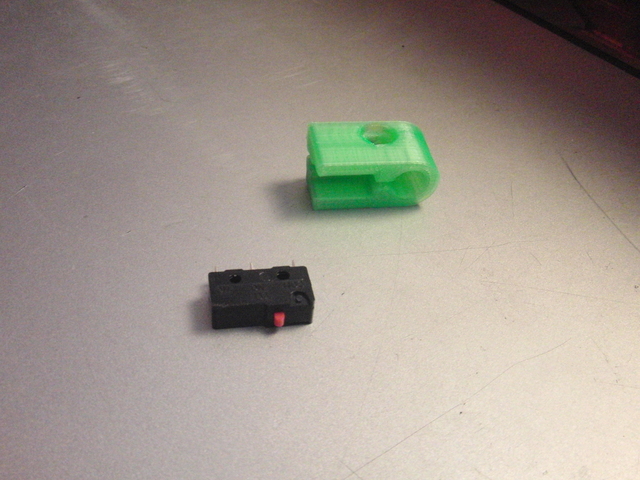
They do not have a part number on them and I have used a few different ones and they all worked the same.
NO lever or roller because it faces downwards and the lever will jam.
Switch with holder:
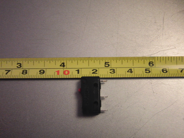
Switch measures 19.5mm long:
Switch measures 9mm high:
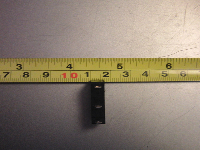
Switch measures 6mm wide:
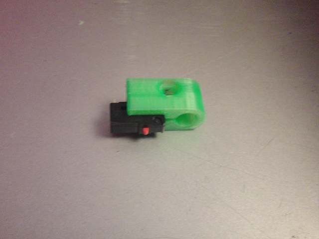
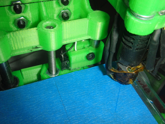
Its held in by the clamping force of the single bolt that holds it on the smooth rod (dab of hot glue to hold in during installation) :
Mounted on the Z smooth rod facing down:
Edited 1 time(s). Last edit at 07/10/2012 10:44PM by Sublime.
NO lever or roller because it faces downwards and the lever will jam.
Switch with holder:

Switch measures 19.5mm long:

Switch measures 9mm high:

Switch measures 6mm wide:

Its held in by the clamping force of the single bolt that holds it on the smooth rod (dab of hot glue to hold in during installation) :

Mounted on the Z smooth rod facing down:

Edited 1 time(s). Last edit at 07/10/2012 10:44PM by Sublime.
| FFF Settings Calculator | Gcode post processors | Geometric Object Deposition Tool Blog |
| Tantillus.org | Mini Printable Lathe | How NOT to install a Pololu driver |
|
Re: Clarification of parts required (and sourcing) August 09, 2012 03:21AM |
Registered: 11 years ago Posts: 51 |
Heya Sublime,
It was great getting to meet you and pick up my hardware and acrylic parts tonight. I'm looking forward to building my Tantillus...
A couple of questions:
Firstly, I was looking at your BOM, and I see no mention of "endstops" under electronics (or elsewhere in the list, for that matter), yet in the build instructions I see step 4 of the electronics section is "Endstop". What is that? An omission, perhaps?
Secondly, we were talking about not all NEMA 17 stepper motors being created equally... the ones I bought from "tony34306" on Ebay were part number 103H5208-0841 seem to all be 2.0 ohm motors and had the description below in the eBay listing. Do these look okay, and will they work for my Tantillus? Or did I get soaked and I would have been better to buy new ones? Ultimately I paid a bit more than $60 USD shipped (to the USA) for a batch of 4 motors. Oddly, when I opened the box, six motors were enclosed... two bonus motors, I suppose.
NEMA 17
Sanyo Denki
STEPPER MOTOR, 1.8 deg 200 steps/rev when full-stepping
PIN5 / RED = A
PIN3 / BLUE= B
PIN4 / YL = A-
PIN2 / ORG = B-
PIN1 / WHT = COMMON
PIN6 / BLK = COMMON
1.6 or 2.0 ohm motors
Current per Phase: 1.2A unipolar .85A bipolar
External Depth: 39mm
External Length / Height: 42mm
External Width: 42mm
Frame Size: 17
Holding Torque: unipolar 42.48 oz/inch (0.3N-m) bipolar 59 oz/inch (.42N-m)
Thanks again,
Frank (Yonderboy)
|
Re: Clarification of parts required (and sourcing) August 09, 2012 03:29AM |
Registered: 13 years ago Posts: 2,947 |
It is actually endstop not endstops. It does not have x and y endstops as all endstops require room to go past the home position before returning to home and Tantillus doesn't have the space for that. All you do is put the head in the back right corner before turning the machine on and it is at home. The endstop is just for Z and will be added to the BOM in the next few days, thanks for pointing it out.
Yes those motors are good, I have the same motors I have in a few of my machines.
Yes those motors are good, I have the same motors I have in a few of my machines.
| FFF Settings Calculator | Gcode post processors | Geometric Object Deposition Tool Blog |
| Tantillus.org | Mini Printable Lathe | How NOT to install a Pololu driver |
|
Re: Clarification of parts required (and sourcing) August 10, 2012 03:23AM |
Registered: 11 years ago Posts: 51 |
Ahh... I just made sense of things (I think). I hadn't quite wrapped my head around what the "endstop" was that pokey9000 was talking about placing an order for. He was referring to the switch, which gets attached to the endstop printed part... which is what you were showing the images with measurements above. I see... now it all comes together.
I'm familiar with those specific switches. Back when I used to hack around with video game arcade cabinets, those were the standard switches (which they referred to as "microswitches" back then) which resided under the big plastic arcade buttons. So that's the item was indeed absent from the BOM? I thought I wasn't going crazy. ;-) So it's just one of them that I need? Got it. I actually may have an old home-built arcade controller in storage with about a dozen of those switches sitting inside it. Time for some cannibalization.
Thanks for confirming that my motors are good. *phew* Glad to know I don't have to hunt down others.
Yonder
|
Re: Clarification of parts required (and sourcing) August 10, 2012 03:31AM |
Admin Registered: 16 years ago Posts: 13,884 |
... when using mechanical switches instead of optocouplers you have to consider debouncing ...
Viktor
--------
Aufruf zum Projekt "Müll-freie Meere" - [reprap.org] -- Deutsche Facebook-Gruppe - [www.facebook.com]
Call for the project "garbage-free seas" - [reprap.org]
Viktor
--------
Aufruf zum Projekt "Müll-freie Meere" - [reprap.org] -- Deutsche Facebook-Gruppe - [www.facebook.com]
Call for the project "garbage-free seas" - [reprap.org]
|
Re: Clarification of parts required (and sourcing) August 10, 2012 09:44AM |
Registered: 12 years ago Posts: 195 |
As you've probably figured out by now, "endstop" has become jargon for "limit detector" and usually refers to whatever device detects the end of travel for an axis. Endstops are usually microswitches or optocouplers ("optos") and interruptors ("flags"), though magnetic hall effect and bare wire contact closures have been known to be used too. "endstop holder" then means exactly what it sounds like.
Unfortunately not all microswitches are the same form factor, which is why I asked Sublime to clarify the dimensions. I wound up ordering one of these Cherry 150g submini microswitches. There are many other options I could have chosen from, but being a mechanical keyboard nut I thought it would be fun to use a limit switch from the famous keyswitch manufacturer. It does have a fairly high actuating force (150g) but on the Z axis I don't think that will be a problem.
Unfortunately not all microswitches are the same form factor, which is why I asked Sublime to clarify the dimensions. I wound up ordering one of these Cherry 150g submini microswitches. There are many other options I could have chosen from, but being a mechanical keyboard nut I thought it would be fun to use a limit switch from the famous keyswitch manufacturer. It does have a fairly high actuating force (150g) but on the Z axis I don't think that will be a problem.
|
Re: Clarification of parts required (and sourcing) August 12, 2012 02:25PM |
Registered: 11 years ago Posts: 51 |
That's some very useful clarification. Thanks a lot, Pokey9000. I may order one of those from Mouser as well, if it turns out that my microswitches aren't adequate.
Sublime... I don't plan to do anything with your code in the Tantillus. Is there any concern about debouncing in this build as VDX has suggested? Are you using microswitches or optocouplers in your Tantillus (Tantilluses? Tantilli?) so far?
Sublime... I don't plan to do anything with your code in the Tantillus. Is there any concern about debouncing in this build as VDX has suggested? Are you using microswitches or optocouplers in your Tantillus (Tantilluses? Tantilli?) so far?
|
Re: Clarification of parts required (and sourcing) August 12, 2012 03:15PM |
Registered: 13 years ago Posts: 2,947 |
Yonderboy Wrote:
-------------------------------------------------------
> Sublime... I don't plan to do anything with your
> code in the Tantillus. Is there any concern about
> debouncing in this build as VDX has suggested?
> Are you using microswitches or optocouplers in
> your Tantillus (Tantilluses? Tantilli?) so far?
All the firmwares have code that hits the endstop and then backs off and finds it again. This does mean the hotend hits the bed when finding home the first time but does not seem to cause a problem. It does make it impossible to have homing switches on X and Y because they do not have room to go past home even a few microns.
I only use microswitches like pictured above and recommend staying away from the opto's as they are prone to noise and seem to require more room because of the flag needed to interrupt the opto. The only thing I would consider changing it too would be a Hall effect sensor because they can detect the distance and start to slow down the axis before it makes it all the way home. This would allow them to be installed on the x and y. But for now we do not have code to use the hall effect sensors so I will stick to the microswitch.
| FFF Settings Calculator | Gcode post processors | Geometric Object Deposition Tool Blog |
| Tantillus.org | Mini Printable Lathe | How NOT to install a Pololu driver |
|
Re: Clarification of parts required (and sourcing) August 13, 2012 03:10AM |
Admin Registered: 16 years ago Posts: 13,884 |
... I have homing/limiting microswitches in my CNC-mill in XYZ, that are accurate to maybe 0.02mm with a lever attached to them.
The axes can even bounce with speed into the switch (had this several times) without breaking them, as slide hits the mechanical borders before wrecking the switch.
Here is a video showing the homing process with an open motor/endstop box: [www.youtube.com]
Viktor
--------
Aufruf zum Projekt "Müll-freie Meere" - [reprap.org] -- Deutsche Facebook-Gruppe - [www.facebook.com]
Call for the project "garbage-free seas" - [reprap.org]
|
Re: Clarification of parts required (and sourcing) August 16, 2012 11:12PM |
Registered: 11 years ago Posts: 51 |
Another couple of parts question...
Sublime, you never added a glass plate for the build platform to the BOM. I know you said you included those in the complete kits, but not in the acrylic or hardware parts kit.
1.) What was the thickness and dimensions of the glass that you had cut for you?
2.) How do you go about attaching it to the build platform?
Cheers,
Frank
|
Re: Clarification of parts required (and sourcing) August 17, 2012 11:44AM |
Registered: 13 years ago Posts: 2,947 |
Yonderboy Wrote:
-------------------------------------------------------
> 1.) What was the thickness and dimensions of the
> glass that you had cut for you?
3mm thick and the depth of the acrylic by the width between the bolt heads. I would give you the actual dimensions but I am 7000 miles from home.
> 2.) How do you go about attaching it to the build
> platform?
It uses two bulldog clips. See the setup section of the build guide on Tantillus.org
| FFF Settings Calculator | Gcode post processors | Geometric Object Deposition Tool Blog |
| Tantillus.org | Mini Printable Lathe | How NOT to install a Pololu driver |
|
Re: Clarification of parts required (and sourcing) August 17, 2012 01:01PM |
Registered: 11 years ago Posts: 939 |
VDX Wrote:
-------------------------------------------------------
> ... I have homing/limiting microswitches in my
> CNC-mill in XYZ, that are accurate to maybe 0.02mm
> with a lever attached to them.
>
> The axes can even bounce with speed into the
> switch (had this several times) without breaking
> them, as slide hits the mechanical borders before
> wrecking the switch.
>
> Here is a video showing the homing process with an
> open motor/endstop box:
> [www.youtube.com]
On a mill you need the levers because there will always be some overshoot and the forces involved would destroy the switches.
On a printer, because of the reduced inertia there will be less overshoot and the forces involved are small, so even if it did overshoot enough to hit the switch on the first approach all that would really happen is it would drop a step, which wouldn't matter since it is resetting the position in that axis anyway.
Personally I think the levers are harmless in this application.
|
Re: Clarification of parts required (and sourcing) August 17, 2012 01:30PM |
Admin Registered: 17 years ago Posts: 7,879 |
Levers reduce the resolution of the switch by a large factor so I wouldn't use them on Z. It doesn't matter much for X and Y unless you home part way through a job for some reason.
[www.hydraraptor.blogspot.com]
[www.hydraraptor.blogspot.com]
|
Re: Clarification of parts required (and sourcing) August 21, 2012 05:32AM |
Registered: 11 years ago Posts: 51 |
So I ultimately bought my my rotary encoder and LCD screen from Suntek Store (I bought lost of extras too, just in case). But I had a couple more questions:
These images are of my rotary encoders:
It was supposed to be a 10-pack, but they only shipped me 7 of them. Jerks!
Also, try as I might, I couldn't find any documentation of what the pinouts would be. Would the pinouts on a part like this be somewhat standard? Sublime, do you have any clear documentation on how you wired yours? And also perhaps some clearer documentation on where it connects on the RAMPS board?
Also, my threads are exactly 7mm, as recommended, but I can't quite make it fit through the hole in the acrylic and engage with the nut. I think it's due to this little metal nib, circled below.
I gather that's there to prevent the encoder from just free-spinning in the hole if it gets a little loose... however we don't have a spot for that "nib" to go, and it's preventing me from having the thread-length to secure the encoder. Would I be best to just file it down to get it out of my way, and then just keep the encoder tightened down as much as possible?
Finally... regarding the LCD screen, here are images of that part that they sold me (I bought six of these, to have a few spares):
I gather this part is relatively standard, and it seems to be this one that they sold me: http://www.goodview-lcd.com/productshow.asp?i=28
However, I'm having trouble finding clear documentation of exactly what the pinouts are on this guy... also, I find the image that you keep referencing, Sublime (http://www.tantillus.org/Images/RAMPS1.4_Tantillus_connections.JPG) to be a bit confusing as to what exactly the pinouts are for the LCD. Can you offer any further clarification for those like me who are buying and wiring our own parts?
These images are of my rotary encoders:


It was supposed to be a 10-pack, but they only shipped me 7 of them. Jerks!
Also, try as I might, I couldn't find any documentation of what the pinouts would be. Would the pinouts on a part like this be somewhat standard? Sublime, do you have any clear documentation on how you wired yours? And also perhaps some clearer documentation on where it connects on the RAMPS board?
Also, my threads are exactly 7mm, as recommended, but I can't quite make it fit through the hole in the acrylic and engage with the nut. I think it's due to this little metal nib, circled below.

I gather that's there to prevent the encoder from just free-spinning in the hole if it gets a little loose... however we don't have a spot for that "nib" to go, and it's preventing me from having the thread-length to secure the encoder. Would I be best to just file it down to get it out of my way, and then just keep the encoder tightened down as much as possible?
Finally... regarding the LCD screen, here are images of that part that they sold me (I bought six of these, to have a few spares):


I gather this part is relatively standard, and it seems to be this one that they sold me: http://www.goodview-lcd.com/productshow.asp?i=28
However, I'm having trouble finding clear documentation of exactly what the pinouts are on this guy... also, I find the image that you keep referencing, Sublime (http://www.tantillus.org/Images/RAMPS1.4_Tantillus_connections.JPG) to be a bit confusing as to what exactly the pinouts are for the LCD. Can you offer any further clarification for those like me who are buying and wiring our own parts?
|
Re: Clarification of parts required (and sourcing) August 21, 2012 06:20AM |
Registered: 11 years ago Posts: 149 |
>Also, my threads are exactly 7mm, as recommended, but I can't quite make it fit through the hole in the acrylic and engage with the nut. I think it's >due to this little metal nib, circled below.
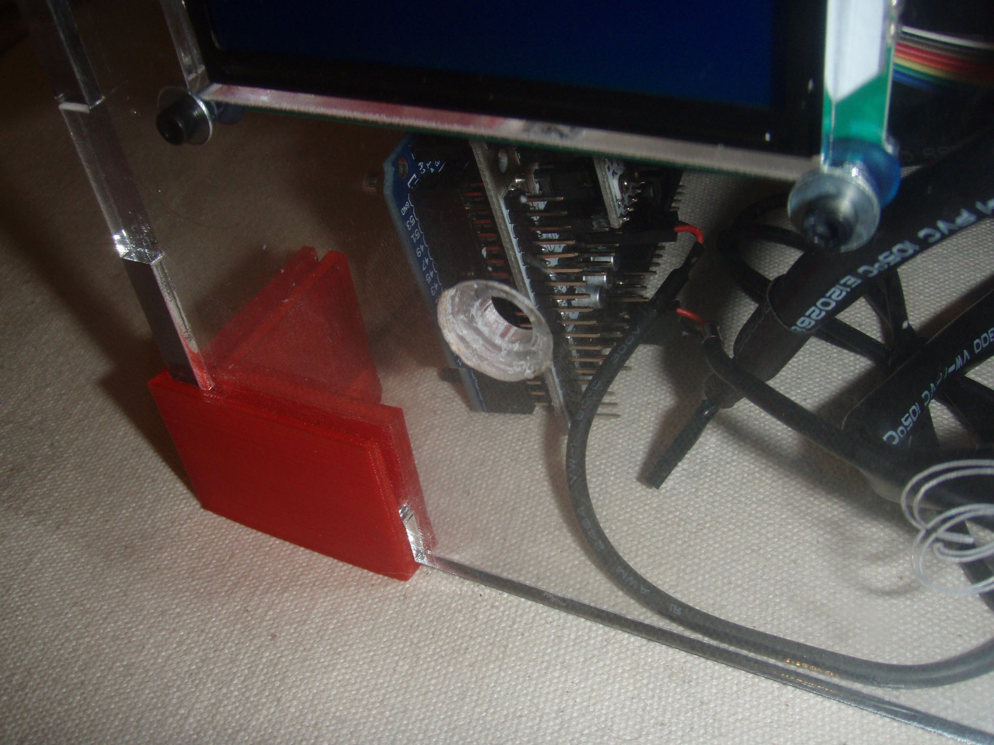
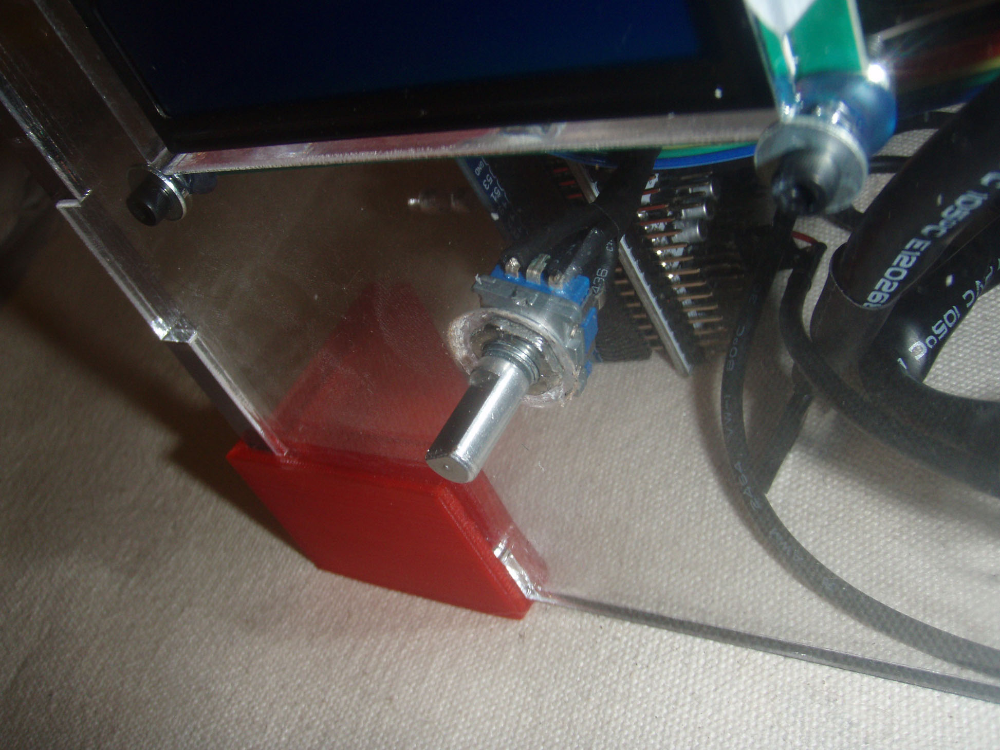
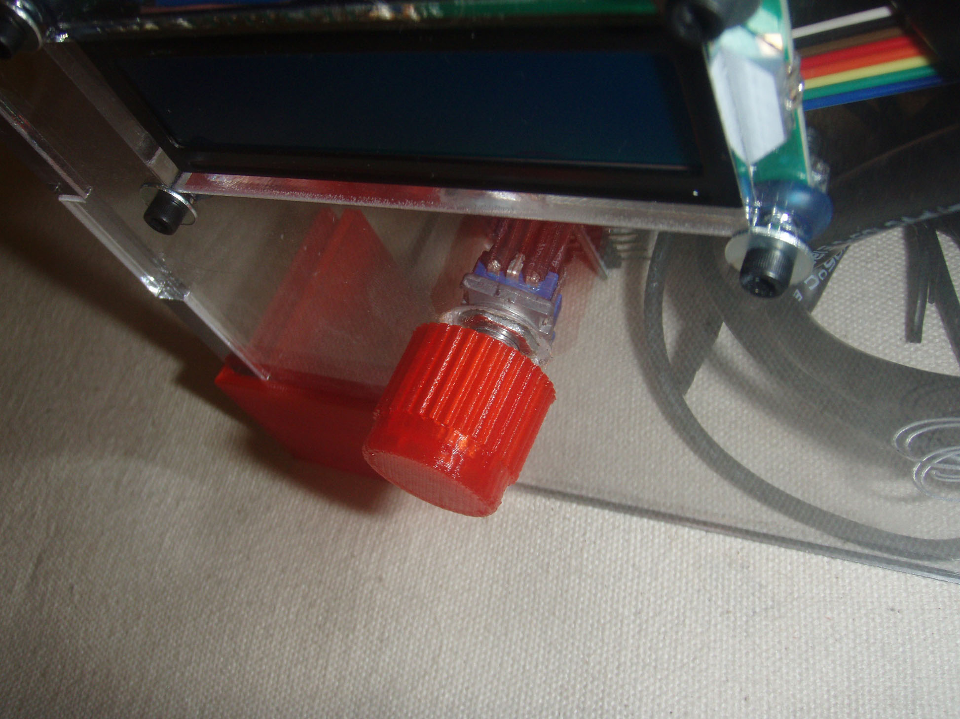
Sublime removed that nib on the encoder he sent to me. I still ended up using a 1/2 inch drill bit to countersink the front of the encoder hole and get more thread engagement because I stripped the very end couple threads on mine. Once the encoder knob is on it covers the countersink modification fairly well. So it doesn't look too shabby, but is still visible from an angle. Pics are attached if you're interested.
7 pieces in a 10-pack? Really?
|
Re: Clarification of parts required (and sourcing) August 21, 2012 02:31PM |
Registered: 11 years ago Posts: 51 |
|
Re: Clarification of parts required (and sourcing) August 22, 2012 12:38AM |
Registered: 13 years ago Posts: 2,947 |
I am back and I have a pinout schematic in the almost every step of the electronics instructions. Electronics To see how the pins of the encoder and the LCD are wired you can see tommyc's Panel max instructions My kits also have a 10k pot soldered between Vcc, Gnd and the sweeper is attached to the contrast pin. I will try and take some pictures of all of this after I get caught up.
Yes I removed the nib and if you do not over tighten the nut you should not strip the threads. The nut should not need to be tightened much at all.
Edited 2 time(s). Last edit at 08/22/2012 04:27PM by Sublime.
Yes I removed the nib and if you do not over tighten the nut you should not strip the threads. The nut should not need to be tightened much at all.
Edited 2 time(s). Last edit at 08/22/2012 04:27PM by Sublime.
| FFF Settings Calculator | Gcode post processors | Geometric Object Deposition Tool Blog |
| Tantillus.org | Mini Printable Lathe | How NOT to install a Pololu driver |
|
Re: Clarification of parts required (and sourcing) August 22, 2012 03:15PM |
Registered: 11 years ago Posts: 51 |
Thanks Sublime.
I'm gonna go grab some 10k pots today so that I can wire one up. Meanwhile, could you re-link tommyc's Panel max instructions... The link above seems wrong.
Sublime Wrote:
-------------------------------------------------------
> I am back and I have a pinout schematic in the
> almost every step of the electronics instructions.
> Electronics To see how the pins of the encoder and
> the LCD are wired you can see tommyc's Panel max
> instructions My kits also have a 10k pot soldered
> between Vcc, Gnd and the sweeper is attached to
> the contrast pin. I will try and take some
> pictures of all of this after I get caught up.
>
> Yes I removed the nib and if you do not over
> tighten the nut you should not strip the threads.
> The nut should not need to be tightened much at
> all.
|
Re: Clarification of parts required (and sourcing) August 22, 2012 04:28PM |
Registered: 13 years ago Posts: 2,947 |
Ok I have fixed the link above [tommyc-reprap.blogspot.ca] also note that Tantillus uses different pins on the Ramps board (see my pinout sheet on the electronics page of the build guide)
Edited 1 time(s). Last edit at 08/22/2012 04:29PM by Sublime.
Edited 1 time(s). Last edit at 08/22/2012 04:29PM by Sublime.
| FFF Settings Calculator | Gcode post processors | Geometric Object Deposition Tool Blog |
| Tantillus.org | Mini Printable Lathe | How NOT to install a Pololu driver |
|
Re: Clarification of parts required (and sourcing) August 23, 2012 11:46AM |
Registered: 12 years ago Posts: 46 |
The .dxf files for the laser cut case parts do not have hole centres, I assume that Blender creates circles as a continuous curve rather than as a centre point and radius. For people building a Tantillus by other means, centre locations would be really handy.
T Case
Edited 1 time(s). Last edit at 08/23/2012 11:47AM by TCase.
T Case
Edited 1 time(s). Last edit at 08/23/2012 11:47AM by TCase.
|
Re: Clarification of parts required (and sourcing) August 23, 2012 01:10PM |
Registered: 11 years ago Posts: 149 |
TCase Wrote:
-------------------------------------------------------
> The .dxf files for the laser cut case parts do not
> have hole centres, I assume that Blender creates
> circles as a continuous curve rather than as a
> centre point and radius. For people building a
> Tantillus by other means, centre locations would
> be really handy.
>
> T Case
I can export DXF's of the Solidworks case models that Willworkforplastic made if you need them. They should be checked against the DXF's from blender to ensure accurate dimensions fyi.
|
Re: Clarification of parts required (and sourcing) August 23, 2012 01:19PM |
Registered: 12 years ago Posts: 46 |
TCase Wrote:
-------------------------------------------------------
> The .dxf files for the laser cut case parts do not
> have hole centres, I assume that Blender creates
> circles as a continuous curve rather than as a
> centre point and radius. For people building a
> Tantillus by other means, centre locations would
> be really handy.
>
> T Case
That would be good, I can check by overlaying them.
Thank you, T Case
|
Re: Clarification of parts required (and sourcing) August 23, 2012 01:50PM |
Registered: 11 years ago Posts: 149 |

|
Re: Clarification of parts required (and sourcing) August 23, 2012 03:15PM |
Registered: 13 years ago Posts: 2,947 |
Thanks Eric,
And Blender does not export any 2D formats so they are exported as stl's and then converted to dxf after.
And Blender does not export any 2D formats so they are exported as stl's and then converted to dxf after.
| FFF Settings Calculator | Gcode post processors | Geometric Object Deposition Tool Blog |
| Tantillus.org | Mini Printable Lathe | How NOT to install a Pololu driver |
|
Re: Clarification of parts required (and sourcing) August 23, 2012 03:47PM |
Registered: 12 years ago Posts: 46 |
|
Re: Clarification of parts required (and sourcing) August 23, 2012 04:00PM |
Registered: 11 years ago Posts: 149 |

Sorry, only registered users may post in this forum.