Yonder's Tantillus Build
Posted by Yonderboy
|
Yonder's Tantillus Build August 12, 2012 02:25PM |
Registered: 11 years ago Posts: 51 |
So I had opportunity last Wednesday to pick up my Tantillus acrylic and hardware parts kits (Thanks Sublime!!), and thus my Tantillus build has begun in earnest. ;-)
First order of business was to assemble the case.
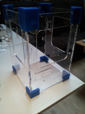
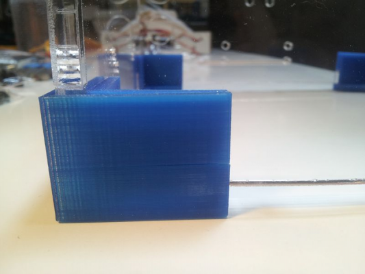
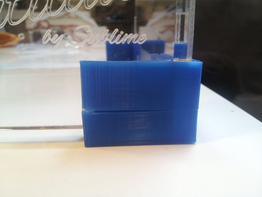
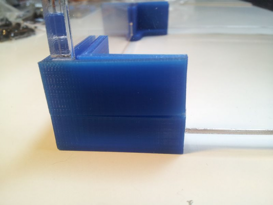
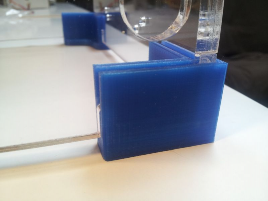
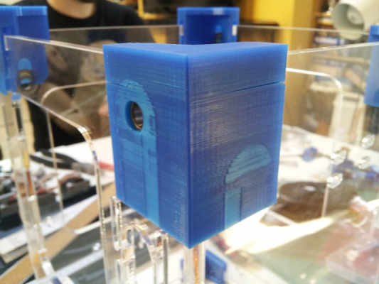
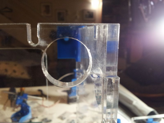
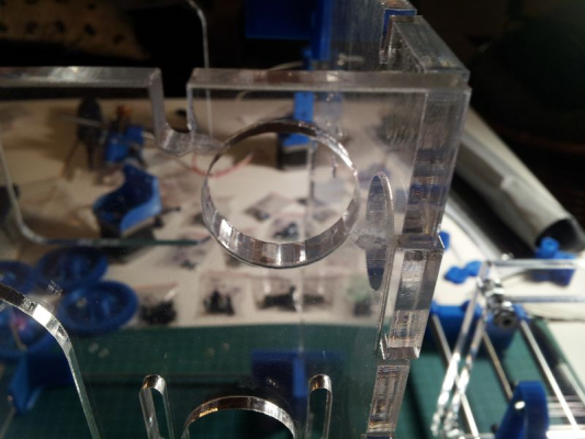
It went together okay, but I did run in to a minor issue. The lower four corner pieces, which like all my printed parts had been printed for me by GeraldO on his Makerbot Replicator in translucent blue PLA (from Reprapers.com) were extremely snug. So much so that in order to get the four pieces to seat fully on the acrylic walls, I had to apply a fair bit of force. I didn't hammer them home, but still on three of the four corners, the outer wall split in the process (see the photos below). It's a mild cosmetic issue, doesn't seem really impact their ability to hold the structure together as the inner walls of those pieces are thicker and intact.
I don't really think there was a sizing issue... Gerald was very meticulous about ensuring that the parts were printed to precise size. I think that they're just a very snug part, by design, so this could be an issue for you. I may reprint them out and swap them later but for now I'm leaving them.
|
Re: Yonder's Tantillus Build August 12, 2012 03:07PM |
Registered: 13 years ago Posts: 2,947 |
This is actually a result of the flow rate on Geralds machine being to high. When you print them on Tantillus they are actually a little loose. This may be a sign that all the parts Gerald printed will be a little tight and could cause issues. Basically if the printers flow is too high (or using slic3r 0.8.4) all the outer walls will be too thick which makes the slot too narrow. When you print it with Tantillus the parts are so precise that the .2mm clearance built into the part design allows some slop and/or play.
| FFF Settings Calculator | Gcode post processors | Geometric Object Deposition Tool Blog |
| Tantillus.org | Mini Printable Lathe | How NOT to install a Pololu driver |
|
Re: Yonder's Tantillus Build August 12, 2012 03:47PM |
Registered: 13 years ago Posts: 2,947 |
I forgot to say the reason why his flow is off is because he did not re-calibrate when he received the new filament which is larger than the Makerbot stuff he was use to. Also he probably needed to re-calibrate even if it was the exact same diameter because he had been using ABS which goes through the extruder at a different rate because of the hardness of PLA vs ABS.
| FFF Settings Calculator | Gcode post processors | Geometric Object Deposition Tool Blog |
| Tantillus.org | Mini Printable Lathe | How NOT to install a Pololu driver |
|
Re: Yonder's Tantillus Build August 12, 2012 04:12PM |
Registered: 11 years ago Posts: 51 |
Note: A lot of what I'm writing up here may be freakin' obvious to you experienced Reprappers. I'm a good tinkerer, but this is my first 3D printer, so I fully expect to run face first into a bunch of total newbie issues that all you guys with two or three printers already have encountered a bunch before an wouldn't even see as a snag. Given that Sublime expects the Tantillus to get into the hands of people of all levels of experience, I figure that documenting my build will perhaps provide an opportunity for that obvious stuff to appear and be identified. Thanks for bearing with me.
Next, on to assembling the X/Y Axis.
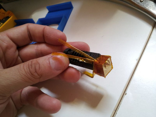
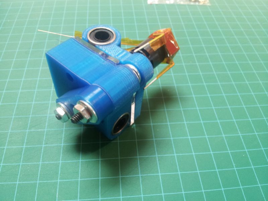
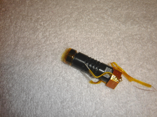
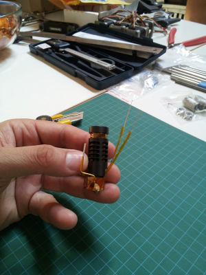
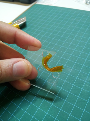
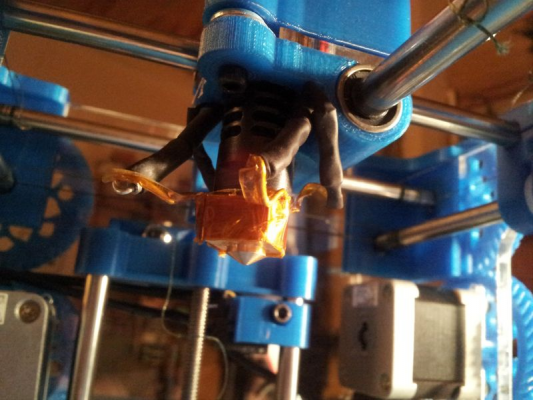
The hotend preparation went okay. I had picked up one of those cartridge heaters from Tinkerine Studio, but it sounds like there may be some issues with running at the 15v that Sublime is recommending for the Tantillus, so I'm waiting for him to do a little experimenting with his own heater before I try to use it myself. Mine is pretty much by the book from Sublime's instructions... no trouble there:
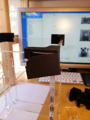
Then it was on to adding the hotend to the carriage assembly. This is where I've hit my first tricky problem. As I went to slide the grooved acrylic plate onto the hotend here...
I was surprised to find that is seemed very loose. This really crappy video may illustrate how loose (sorry, had trouble holding my phone in a good position to while manipulating the parts):
loose hotend mounting plate
I wasn't sure where the problem might have been. Sublime had some issues with precision of the laser-cut acrylic parts previously, but this batch looked pretty good, so I assume that the grooved plate was to spec. Perhaps the issue is that the hotends that I purchased from Hotends.com were the newer J-Head Mk V-B, and perhaps the PEEK has a mounting groove with subtly different dimensions than the older J-Head Mk IV.
I thought I'd just proceed ahead and see if the completed carriage would hold or grip the hotend better. After finishing putting it together and tightening it down, it seems to have a ridiculous amount of extra wiggle and play (see in the other crappy video below).
loose hotend in carriage
Gerald and I are working on the next steps of the build today. We'll probably try to work around this by padding out the inside of the mounting groove and perhaps the inside edge of the acrylic plate with Kapton tape. I'm curious if you have any better suggestions for us, Sublime?
|
Re: Yonder's Tantillus Build August 12, 2012 04:26PM |
Registered: 11 years ago Posts: 116 |
|
Re: Yonder's Tantillus Build August 12, 2012 04:55PM |
Registered: 11 years ago Posts: 51 |
Sublime Wrote:
-------------------------------------------------------
> This is actually a result of the flow rate on
> Geralds machine being to high. When you print them
> on Tantillus they are actually a little loose.
> This may be a sign that all the parts Gerald
> printed will be a little tight and could cause
> issues. Basically if the printers flow is too high
> (or using slic3r 0.8.4) all the outer walls will
> be too thick which makes the slot too narrow. When
> you print it with Tantillus the parts are so
> precise that the .2mm clearance built into the
> part design allows some slop and/or play.
Interesting. By contrast, the top and bottom parts of the carriage seemed to be pretty much perfect. The linear bearings slid in absolutely perfectly, yet nicely snug. It'll be interesting to see which parts might be off a bit later. Gerald offered to reprint the corners at some point if needed, but I'm not going to worry about it right now.
Any thoughts on the loose hotend, Sublime?
|
Re: Yonder's Tantillus Build August 12, 2012 06:19PM |
Registered: 13 years ago Posts: 2,947 |
Yonderboy Wrote:
-------------------------------------------------------
> Then it was on to adding the hotend to the
> carriage assembly. This is where I've hit my
> first tricky problem. As I went to slide the
> grooved acrylic plate onto the hotend here...
At this stage it should be loose because the hotend is not held in by the groove but instead by the portion above the groove being clamped inside the upper carriage.
> I thought I'd just proceed ahead and see if the
> completed carriage would hold or grip the hotend
> better. After finishing putting it together and
> tightening it down, it seems to have a ridiculous
> amount of extra wiggle and play (see in the other
> crappy video below).
This is where is should be tight. I had one that was not tight and I wrapped a few layers of kapton around it but have not updated the instructions with the pictures.
Wrap the top portion of the hotend in a few layers of Kapton until it fits snugly in the upper carriage as seen in this picture.
> Gerald and I are working on the next steps of the
> build today. We'll probably try to work around
> this by padding out the inside of the mounting
> groove and perhaps the inside edge of the acrylic
> plate with Kapton tape. I'm curious if you have
> any better suggestions for us, Sublime?
This is what I was planning on recommending to everyone. Do not worry about the groove fit only the fit in the carriage.
Edited 1 time(s). Last edit at 08/12/2012 06:19PM by Sublime.
| FFF Settings Calculator | Gcode post processors | Geometric Object Deposition Tool Blog |
| Tantillus.org | Mini Printable Lathe | How NOT to install a Pololu driver |
|
Re: Yonder's Tantillus Build August 12, 2012 06:21PM |
Registered: 13 years ago Posts: 2,947 |
Lisa M Wrote:
-------------------------------------------------------
> I had splits on my upper corner too... pushed the
> rod right through ...guess I'm all thumbs.
> However, it was nothing that a little plastic glue
> couldn't fix.
If you give me a little while to get other things caught up I will send you new corners. I am sure this is a result of mising info in the instructions.
-------------------------------------------------------
> I had splits on my upper corner too... pushed the
> rod right through ...guess I'm all thumbs.
> However, it was nothing that a little plastic glue
> couldn't fix.

If you give me a little while to get other things caught up I will send you new corners. I am sure this is a result of mising info in the instructions.
| FFF Settings Calculator | Gcode post processors | Geometric Object Deposition Tool Blog |
| Tantillus.org | Mini Printable Lathe | How NOT to install a Pololu driver |
|
Re: Yonder's Tantillus Build August 12, 2012 06:25PM |
Registered: 13 years ago Posts: 2,947 |
Yonderboy Wrote:
-------------------------------------------------------
> Interesting. By contrast, the top and bottom
> parts of the carriage seemed to be pretty much
> perfect. The linear bearings slid in absolutely
> perfectly, yet nicely snug. It'll be interesting
> to see which parts might be off a bit later.
> Gerald offered to reprint the corners at some
> point if needed, but I'm not going to worry about
> it right now.
Strange, it could be as simple as part of the roll was oversized and the rest was the right size so some parts came out overstuffed. I know the corners printed on my prusa are tight because of layer alignment and too high of flow some times.
| FFF Settings Calculator | Gcode post processors | Geometric Object Deposition Tool Blog |
| Tantillus.org | Mini Printable Lathe | How NOT to install a Pololu driver |
|
Re: Yonder's Tantillus Build August 12, 2012 06:26PM |
Registered: 11 years ago Posts: 5 |
I wasn't so lucky with the corners:
I am afraid to try and fully seat the rest of them. Is it better to print them in ABS instead of PLA?
Edited 1 time(s). Last edit at 08/12/2012 06:27PM by John707.
I am afraid to try and fully seat the rest of them. Is it better to print them in ABS instead of PLA?
Edited 1 time(s). Last edit at 08/12/2012 06:27PM by John707.
|
Re: Yonder's Tantillus Build August 12, 2012 06:33PM |
Registered: 11 years ago Posts: 116 |
> If you give me a little while to get other things
> caught up I will send you new corners. I am sure
> this is a result of mising info in the
> instructions.
It's alright. It was just one top corner. It cracked minorly during case assembly.
Then when I was putting the rods in, it completely cracked along a layer line all the way around but I used some clamps and plastic glue and all is well now. I don't think it was an issue on instructions. More an issue of not being as mindful about how delicate some of the thinner printed parts can be. With one set of hands it can be a bit difficult to hold everything.
|
Re: Yonder's Tantillus Build August 12, 2012 06:38PM |
Registered: 13 years ago Posts: 2,947 |
John707 Wrote:
-------------------------------------------------------
> I am afraid to try and fully seat the rest of
> them. Is it better to print them in ABS instead
> of PLA?
Hey John are you sure your Cupcake prints things exactly the right size? Have you printed a 40mm calibration cube? But to solve this you should just scale up the parts a couple of percent to give them some room. I think ABS would be worse since it tends to shrink and make things smaller.
Edited 1 time(s). Last edit at 08/12/2012 09:27PM by Sublime.
| FFF Settings Calculator | Gcode post processors | Geometric Object Deposition Tool Blog |
| Tantillus.org | Mini Printable Lathe | How NOT to install a Pololu driver |
|
Re: Yonder's Tantillus Build August 12, 2012 08:23PM |
Registered: 11 years ago Posts: 5 |
|
Re: Yonder's Tantillus Build August 12, 2012 08:51PM |
Registered: 13 years ago Posts: 2,947 |
Try scaling one up 2% and print it.
| FFF Settings Calculator | Gcode post processors | Geometric Object Deposition Tool Blog |
| Tantillus.org | Mini Printable Lathe | How NOT to install a Pololu driver |
|
Re: Yonder's Tantillus Build August 12, 2012 09:20PM |
Registered: 11 years ago Posts: 7 |
|
Re: Yonder's Tantillus Build August 12, 2012 09:22PM |
Registered: 11 years ago Posts: 7 |
BTW, I've found that this part makes empirically determining the flow rate quite easy and fun!
Filament diameter test
I've found that the measurement I get with my micrometer needs to be increased by almost 10% to get the correct flow rate. Perhaps a flaw in the Replicator's design? I'm not sure.
Edited 1 time(s). Last edit at 08/12/2012 10:18PM by GeraldO.
Filament diameter test
I've found that the measurement I get with my micrometer needs to be increased by almost 10% to get the correct flow rate. Perhaps a flaw in the Replicator's design? I'm not sure.
Edited 1 time(s). Last edit at 08/12/2012 10:18PM by GeraldO.
|
Re: Yonder's Tantillus Build August 14, 2012 04:12AM |
Registered: 11 years ago Posts: 51 |
Yesterday's update: busy day on my Tantillus build. Gerald came by and we worked for a little while on it together.
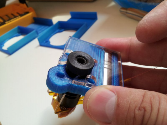
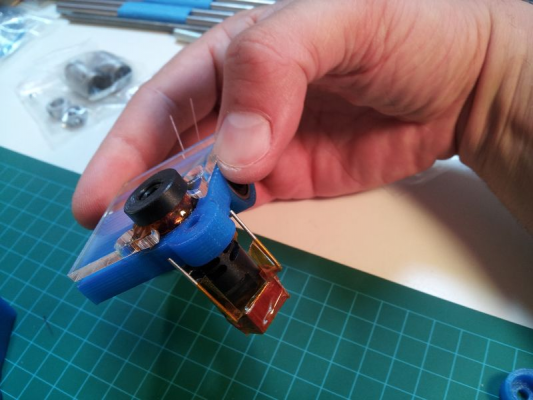
Ultimately prior to seeing your response here, Sublime, I had solved the problem of the loose hotend by padding out the thickness of the groove by wrapping Kapton tape around it, and also wrapping tape on the inner edge of the acrylic piece. You can see below.
Sublime's recommendation was to pad out the top of the hotend with extra tape, but this alternative seems to have done a great job of increasing the friction and grip too. And the end result was that the hotend is solid and firm now, and we proceeded to complete the X/Y assembly.
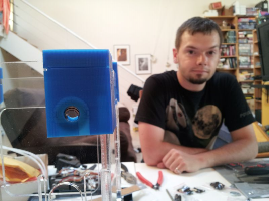
Then we went on to install the rods and that's where we hit a snag. As we tried to get the top corners fully on, most of those split as well. It's pretty clear we ended up with a sizing issue on all of the corners. (You can see how unimpressed Gerald was with the situation in the top shot)
So we decided to wrap on the assembly for the day. Gerald took my case home with him so that he could reprint the corners for me sized correctly.
Alas, after he left I was feeling restless and wanted to continue my assembly anyway.
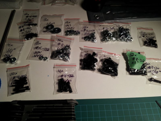
Firstly, finally decided to count and label my parts in all of the bags. I realized that there were enough of a variety of similar sized and length parts that I figured that if I didn't do it, I'd get somewhat confused later. It would be great if this were done for your customers in your preparation of future hardware kits, Sublime.
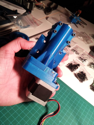
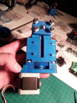
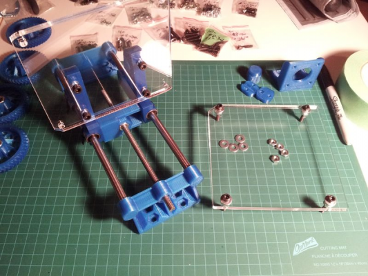
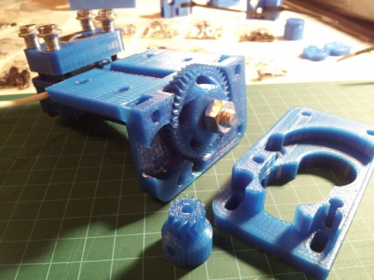
Next, I decided to jump ahead and put together the extruder. That part went completely smoothly. Discarding the support structure, filing away the excess material, and then installing additional other parts - no problems at all. The only part that I skipped was installing the nuts and set screws into the motor's drive gear, since we need to reprint the gear because its teeth were a little off.
I also started putting together the Z-axis assembly. That was also fairly straightforward... although there were a couple of confusing parts. However it seems like Sublime has updated his build instructions today, so I'll go check if he's clarified those parts of the build.
More updates to come...
|
Re: Yonder's Tantillus Build August 14, 2012 11:20AM |
Registered: 11 years ago Posts: 7 |
|
Re: Yonder's Tantillus Build August 14, 2012 11:50AM |
Registered: 12 years ago Posts: 195 |
Looks like you're using the same color filament I'm using for my case. Is that the repraper.com blue?
After assembling your extruder and setting the spacing for the big gear, did you wind up with any play in the hobbed bolt? I added a thin 5/8" washer between the bearing and gear to clean it up but it doesn't seem like that's intentional. It seems to work fine and there's more than enough room for the motor gear.
After assembling your extruder and setting the spacing for the big gear, did you wind up with any play in the hobbed bolt? I added a thin 5/8" washer between the bearing and gear to clean it up but it doesn't seem like that's intentional. It seems to work fine and there's more than enough room for the motor gear.
|
Re: Yonder's Tantillus Build August 15, 2012 03:11AM |
Registered: 11 years ago Posts: 51 |
GeraldO Wrote:
-------------------------------------------------------
> I ended up getting the corners to fit like a
> glove: I scaled them up by 2% and decreased the
> flow rate quite a bit. It now fits snug, but just
> enough that you don't need a dremel to take them
> off
The lesson that Gerald and I learned in this process is clearly that if you are printing your parts with the intention of getting an acrylic parts kit from Sublime, you want to be very careful on the corner sizing. All eight of the corners we had originally printed were way too snug. I pounded on the bottom ones hard enough that they're holding and we're leaving them in place right now. But as I showed in images right at the top of this post, 3 of the 4 of them split in the process. When we get a chance, we'll reprint them... but I'm gonna need to cut or grind them off as they're on so tight.
The top corners also split in the process of sliding them on, and that was the cue for Gerald to reprint them. Those parts really need to be snug yet removable if you need to troubleshoot any rod or bearing issues. Unfortunately, they were on so tight that when Gerald pulled one of them off, it cracked the acrylic case corner off. Those corners are actually connected by a small enough bit of acrylic due to the circular bearing cutout, that they're probably more fragile than you'd expect.
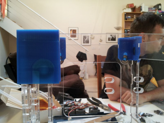
Luckily, with the help of some Loctite Plastic Super Glue, I glued it back together with a very firm bond, and I'm not concerned for my Tantillus' structural integrity long-term. Here's a couple of crappy shots of the break right after gluing.
Just waiting now for Gerald to finish reprinting my top rear right corner piece, so I should be able to reattempt my rod assembly tomorrow. ;-)
-------------------------------------------------------
> I ended up getting the corners to fit like a
> glove: I scaled them up by 2% and decreased the
> flow rate quite a bit. It now fits snug, but just
> enough that you don't need a dremel to take them
> off

The lesson that Gerald and I learned in this process is clearly that if you are printing your parts with the intention of getting an acrylic parts kit from Sublime, you want to be very careful on the corner sizing. All eight of the corners we had originally printed were way too snug. I pounded on the bottom ones hard enough that they're holding and we're leaving them in place right now. But as I showed in images right at the top of this post, 3 of the 4 of them split in the process. When we get a chance, we'll reprint them... but I'm gonna need to cut or grind them off as they're on so tight.
The top corners also split in the process of sliding them on, and that was the cue for Gerald to reprint them. Those parts really need to be snug yet removable if you need to troubleshoot any rod or bearing issues. Unfortunately, they were on so tight that when Gerald pulled one of them off, it cracked the acrylic case corner off. Those corners are actually connected by a small enough bit of acrylic due to the circular bearing cutout, that they're probably more fragile than you'd expect.
Luckily, with the help of some Loctite Plastic Super Glue, I glued it back together with a very firm bond, and I'm not concerned for my Tantillus' structural integrity long-term. Here's a couple of crappy shots of the break right after gluing.
Just waiting now for Gerald to finish reprinting my top rear right corner piece, so I should be able to reattempt my rod assembly tomorrow. ;-)
|
Re: Yonder's Tantillus Build August 15, 2012 03:48AM |
Registered: 11 years ago Posts: 51 |
pokey9000 Wrote:
-------------------------------------------------------
> Looks like you're using the same color filament
> I'm using for my case. Is that the repraper.com
> blue?
Hey Pokey... yep, that's repraper.com blue PLA. I only bought 1.7mm in that colour for Gerald to use in printing my parts. He was able to do all the needed parts with less than a full 1KG spool, although we may be dipping into spool #2 soon given all the reprints due to failures. I guess we're going to end up with twin Tantilli, Pokey. ;-)
Myself I've snagged repraper's black, white, purple, orange, red and glow-in-the-dark blue in 3mm PLA to play with just as soon as my Tantillus is built. I'm looking forward to it.
> After assembling your extruder and setting the
> spacing for the big gear, did you wind up with any
> play in the hobbed bolt? I added a thin 5/8"
> washer between the bearing and gear to clean it up
> but it doesn't seem like that's intentional. It
> seems to work fine and there's more than enough
> room for the motor gear.
Yes, there was indeed some play on my hobbed bolt too. However, once I slipped a small scrap of 3mm filament through the guide hole and into the installed hobbed bolt's teeth (and under compression from the skate bearing), it settles into the needed height pretty firmly. I was having trouble setting the spacing effectively, but I just tried your suggestion of adding the thin washer and that helped in my case too.
Gerald had printed the herringbone versions of these gears for me, rather than the newer versions with conventional teeth. I may swap them out later if these present a problem.
|
Re: Yonder's Tantillus Build August 15, 2012 08:48AM |
Registered: 11 years ago Posts: 51 |
Worked a little more on my build tonight, but I didn't make a lot of progress as I'm still waiting on Gerald to reprint a few parts for me. However, I did come up with a couple of questions...
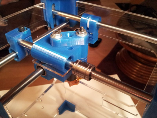
1.) I've had the problem of one of the linear bearings on my carriage regularly popping out and staying on the rod (see the image below). Is there a recommended way to better secure the bearing in the carriage head?
2.) I was going to ask what the two holes in the back acrylic wall are intended for? I didn't see them in any of the other images. Then I was rereading the build instructions tonight and I came across this image, which gave away the secret, I think... I'm guessing that the hole below is so that you can easily pass through a USB cable as needed?
I hope to make more progress on my build tomorrow.
|
Re: Yonder's Tantillus Build August 15, 2012 09:53AM |
Registered: 13 years ago Posts: 2,947 |
Yonderboy Wrote:
-------------------------------------------------------
> 1.) I've had the problem of one of the linear
> bearings on my carriage regularly popping out and
> staying on the rod (see the image below). Is
> there a recommended way to better secure the
> bearing in the carriage head?
The acrlic plate is supposed to be pressing against them to help hold them in but as shown by WillWorkForPlastic in his metric build log the slicing software can cause the carriage to be printed in a way that stops the bearing from touching the acrylic plate. I would think the simplest solution of wrapping it in Kapton would work or applying a small dab of glue. The more involved way would be to take it apart and remove the offending areas of plastic and maybe heat the carriage just enough to push it closed more to apply more force that way.
> 2.) I was going to ask what the two holes in the
> back acrylic wall are intended for? I didn't see
> them in any of the other images. Then I was
> rereading the build instructions tonight and I
> came across this image, which gave away the
> secret, I think... I'm guessing that the hole
> below is so that you can easily pass through a USB
> cable as needed?
Yes it is for the USB cable. I did not have it on the first one and it was really hard to get it plugged in.
All of this really shows how every printer prints it differently.
| FFF Settings Calculator | Gcode post processors | Geometric Object Deposition Tool Blog |
| Tantillus.org | Mini Printable Lathe | How NOT to install a Pololu driver |
|
Re: Yonder's Tantillus Build August 21, 2012 05:01AM |
Registered: 11 years ago Posts: 51 |
So I've been pretty busy since last week and over the weekend, so I had been left with precious little time to spend on my Tantillus build. Still I've made *some* progress...
Over the weekend, I found a framing shop that could cut my glass print bed for me, and I found some #8 - 32 1.5" pan head machine screws to replace my too-short 1" screws on my build platform too. The framing shop dude was a little imprecise as he cut the glass, and he did a sloppy metric to imperial conversion (cause he had to cut in imperial for some reason) and the glass he cut for me was about 2mm narrower between the bolts than it needed to be. Still my dimensions on the glass bed are 105.3mm x 127.3mm x 2.5mm thick... which, I assume, is precise enough for size. That I should still have the needed 100mm x 100mm build space, right? I still haven't worked out how the Tantillus' software homes correctly on the X/Y axis so that it keeps within that build area... but I'm sure I'll start to understand that as I fire it up and start playing with Pronterface.
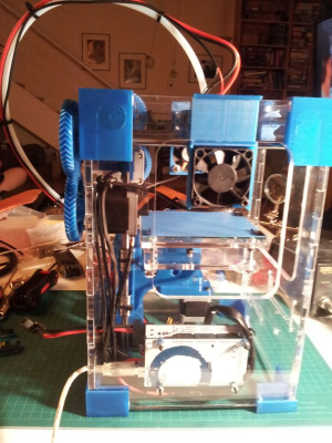
Here are the Z axis and bed as currently installed:
As of the weekend, my shipment from Suntek Store in China still hadn't arrived, so I was still waiting on my LCD screen and my rotary encoder (update: they arrived today), but I figured I'd proceed as far with the physical build as I could.
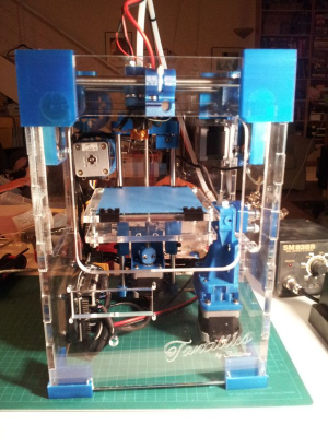
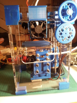
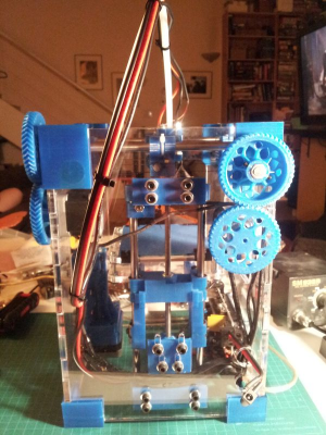
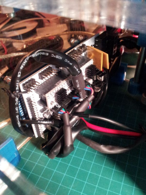
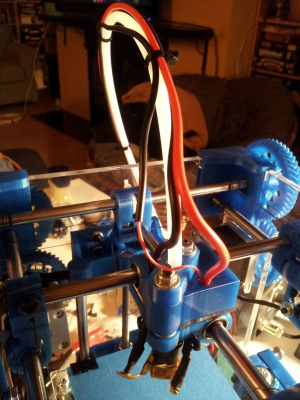
By the end of Sunday, I had assembled all the main components... soldered, wired and installed the motors... installed the Arduino and RAMPS boards... run the wiring to the thermistor and hotend along the Bowden tube... installed the fans... and run all the wiring throughout the case keeping clear of the moving parts. The only parts that I didn't install yet were the missing LCD and rotary encoder.
I also haven't yet put any power into my Tantillus. I will soon, although stories of flaming stepper drivers aren't exactly encouraging. ;-)
Meanwhile, here are some more crappy photos of the build so far:
Hopefully I'll have time in the upcoming week to wire my remaining parts and fire it all up for some testing. I also have a couple more parts questions, but I'l raise those in the other thread.
|
Re: Yonder's Tantillus Build August 21, 2012 05:48AM |
Registered: 11 years ago Posts: 149 |
Love your crappy photos Yonder, your machine is looking great. Nice documentation on your build too, it's been quite helpful for me.
I believe that if the carriage is moved all the way to into each corner and the extruder outlet is above the glass the entire time then you still have the entire build area. Assuming your carriage is able to move the entire 100mm distance in both X and Y that is.
If you're concerned about plugging in, I'd think it a good idea to listen closely for a faint crackling sound immediately after the power is supplied and keep one hand on the plug so you can yank it quickly if you need to. The crackling sound preceded the smoke/flames by a couple seconds for me, so if it happens for you then maybe you can pull the plug more quickly than I did.
|
Re: Yonder's Tantillus Build August 21, 2012 02:29PM |
Registered: 11 years ago Posts: 51 |
Thanks Eric.
In checking my carriage movement, it seems to have more than 100mm total physical range of movement in each direction. As such, if pushed right to the corners, it can seem to position the head a couple of mm off the glass build platform. But given that my glass platform is larger than 100mm in each direction, I assumed that it may be no problem if the software does constrain the movement of the head to a 100mm range on each axis. As I said, lacking endstops, I don't really know what exactly constrains the X/Y axis movement on this printer, or where it would ultimately home.
I think I read in one of the other threads that one is supposed to manually home the head to the back right corner before you power up... is that right? So, does that mean that if the back right corner is successfully over the glass, and the head can move 100m both on X and Y from that position and remain over glass, then I'm okay? Not clear on that.
As for plugging it in... I'm probably being unnecessarily paranoid. Just to be sure, I am going to do one final test with my multimeter tonight to ensure that I don't accidentally reverse my polarity and fry the works. I don't have a handy Mr. Sublime doing my wiring for me.
That said, electricity is pretty dang fast... it would seem to me that if you hear a crackling sound, you're probably already too late. Wouldn't you agree? ;-)
In checking my carriage movement, it seems to have more than 100mm total physical range of movement in each direction. As such, if pushed right to the corners, it can seem to position the head a couple of mm off the glass build platform. But given that my glass platform is larger than 100mm in each direction, I assumed that it may be no problem if the software does constrain the movement of the head to a 100mm range on each axis. As I said, lacking endstops, I don't really know what exactly constrains the X/Y axis movement on this printer, or where it would ultimately home.
I think I read in one of the other threads that one is supposed to manually home the head to the back right corner before you power up... is that right? So, does that mean that if the back right corner is successfully over the glass, and the head can move 100m both on X and Y from that position and remain over glass, then I'm okay? Not clear on that.
As for plugging it in... I'm probably being unnecessarily paranoid. Just to be sure, I am going to do one final test with my multimeter tonight to ensure that I don't accidentally reverse my polarity and fry the works. I don't have a handy Mr. Sublime doing my wiring for me.

That said, electricity is pretty dang fast... it would seem to me that if you hear a crackling sound, you're probably already too late. Wouldn't you agree? ;-)
|
Re: Yonder's Tantillus Build August 21, 2012 06:44PM |
Registered: 11 years ago Posts: 149 |
I think you're right about the home being the back right and if it can move 100mm in X or Y while staying over the glass then you're okay. Looking at my Tantillus, the extruder tip also moves past the glass by about 2mm when positioned all the way to the left. Should have checked that before opening my mouth in the first place. 
This extruder/glass overshoot brings up an interesting point because it looks as though the extruder tip could potentially come into contact with the screw heads on the left side when the glass is less than 1mm or so away from the extruder tip in the Z direction. So if the software went nutty during the first 1mm or so of a build and sent the carriage all the way to one of the left corners, the extruder tip might smack a screw head. I'm thinking the software is stable enough that this hasn't been a problem.
Not sure about the XY endstops/constraints either, guessing it's all taken care of in the software.
Haha yeah I'd definitely agree the damage would already be done (or most of it at least) if you do hear the crackling, but you might be able to avoid the smokey fiery ordeal. It was kinda fun though, so maybe just let it ride if you're like me and you have a penchant for blowing stuff up

|
Re: Yonder's Tantillus Build August 22, 2012 12:28AM |
Registered: 13 years ago Posts: 2,947 |
Sorry I have been flying for the last day.
Homing is done with the power off by putting the head in the back right corner. The firmware then limits it to 100 in X and Y.
The nozzle not being over the bead is most likely because the upper Z bracket is not centered (added to the instructions). [www.tantillus.org]
Homing is done with the power off by putting the head in the back right corner. The firmware then limits it to 100 in X and Y.
The nozzle not being over the bead is most likely because the upper Z bracket is not centered (added to the instructions). [www.tantillus.org]
| FFF Settings Calculator | Gcode post processors | Geometric Object Deposition Tool Blog |
| Tantillus.org | Mini Printable Lathe | How NOT to install a Pololu driver |
|
Re: Yonder's Tantillus Build August 26, 2012 08:07PM |
Registered: 11 years ago Posts: 51 |
So it's been a little while since I updated my build progress. Busy days at work have really prevented me from spending as much time on it as I'd like.
Btw, I have one little bit of feedback worth offering you to all, which I've learned along the way. If you decide, like I did, to buy just the hardware and acrylic kits, and then source all your own parts, you'll probably spend the bulk of your time trying to get the wiring right. The biggest difference from my own build compared to everyone putting together a complete kit, seems to be how much time I've needed to spend hunched over my soldering iron with my heatshrink tubing trying to wire everything correctly, as I haven't been able to rely on wonderfully pre-wired components courtesy of Sublime.
On one hand it has soaked up a TON of extra time... but on the other hand I do feel like I have a much more intimate understanding of how my device is wired and connected, which I hope will serve me in the long run. Especially as I tweak and troubleshoot down the road, or perhaps if I decide to build another one. ;-)
Now... back to my progress....
Late last week, I started getting stuck-in with wiring my LCD. As I mentioned above, the parts that took longest to arrive for me was the LCD screen and rotary encoder which I got from Suntek Store in China. I ultimately bought 6 LCDs and 10 rotary encoders (although they only shipped me 7) because the additional cost was quite minimal, and I have ambitions to do further future Arduino-based projects, so it seemed worthwhile to have some spares (also, Sublime warned that the cheap Chinese parts can easily arrive DOA).
As such, before getting going with wiring the LCD to the wiring to go into my Tantillus, I whipped out my old Arduino Duemilanove and a breadboard so that I could test drive one of these LCDs and confirm that they worked as expected. I followed the tutorial posted over on Lady Ada's site (http://learn.adafruit.com/character-lcds) and before I knew it, I had one of them up and functioning perfectly.
Nice! Now to make it work on my Tantillus.
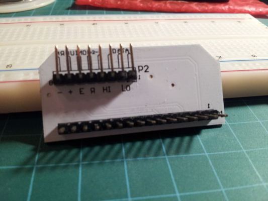
While I was going to assemble it totally manually, I was fortunate that GeraldO had gotten to meet up with Sublime the day before at the local 3D printing meetup, and Sublime had passed on this little baby to him so that I could try it out:
It's a slick little board that Sublime had made, which as you can see, is designed to be soldered right onto the back of the LCD panel and makes the process of adding in the contrast potentiometer (actually it has a tiny one built right on) and wiring up the specific eight connectors required a breeze. Nice!
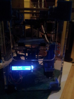
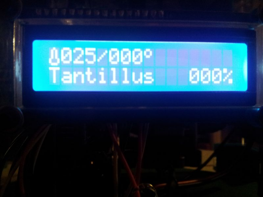
Before the evening was through, I had uploaded Marlin onto the Arduino Mega and had fired up the LCD:
At this point, I hadn't yet put any power through the RAMPS itself. The LCD is being powered solely by the Arduino running just of the USB power from my computer. Interestingly the thermistor seems to be getting enough power and is correctly reading the ambient temperature at 25 degrees.
That was it for this night (Thursday), but my next goals for the upcoming evenings were as follows;
1) I needed to wire up a rotary encoder
2) I needed to finally grab some big hairy ones and put ~5 amps at 15 volts through the RAMPS and hope that nothing decides to cause one of my steppers to burst into flames. ;-)
3) I wanted to get started testing out my steppers and confirming that all of the other wiring that I had done by hand thus far was correct.
More fun to come...
|
Re: Yonder's Tantillus Build August 26, 2012 09:24PM |
Registered: 11 years ago Posts: 51 |
So, on to the recap of the activities of Friday and Saturday night... unfortunately for me, my wife had made plans for us both Friday and Saturday evening, and I had a busy day planned Saturday. Therefore, all of my tinkering this weekend has been relegated to the hours of about 12:30am to 5:00am on both Friday and Saturday nights. I wish I could say this is the first time, but like many I'm quick to sacrifice sleep if it lets me make progress on my projects. Ahh, the fun of hobbies. ;-)
I decided to sidestep worrying about the rotary encoder just yet, knowing that I could just use Pronterface for now and work on that a bit later. I wanted to get on to some power. I connected up one of the two Toshiba laptop power supplies (15v 5/6A) that I'd picked up off some company on eBay.
Nothing.
Okay, I was wary of sparks or smoke but that was pretty underwhelming on every level. A bit of probing around with my multimeter and I deduced that the problem was the barrel connector that I'd picked up from my local electronics parts store.
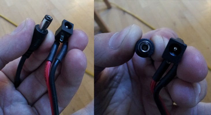
The day I had grabbed the barrel connectors, I didn't actually have the power supply with me, and I couldn't be sure that I could correctly eyeball the needed connector... so I just picked up both a 2.1 and a 2.5mm connector thinking that one of them was bound to fit (and at around a buck each, it was cheap enough to be worth saving the time to come back). After testing the fit at home, it seemed my power supply had a 2.5mm connector as that one fit smoothly and slid all the way in flush. I had soldered that connector on to the end of a little lead of 14g zip wire as you can see in the picture, the other end was connected to the power harness that plugs into the RAMPS board. I had just left it dangling out the upper hole in the back acrylic wall since I never got the connector plug housing printed, and anyway I didn't think it would fit with this precise shape of plug. Probably good that I didn't go to the trouble anyway. It turns out (I think) that the male positive pin in the barrel connector was somehow not making contact, so no juice was making it in to my RAMPS at all. Goes to show... you always gotta confirm that your connections are connecting. ;-)
I really wanted to make some more progress, and it looked like the barrel connector was gonna be a bust. I thrashed around my house and in some random rubbermaid bins of electronics parts looking for something that could act as a quick connect, that was also at least 14g wire and a beefy enough connector that carrying 15v at 6A over long periods of time wouldn't ultimately melt it. That's over the specs for the standard molex connectors that I have among my spare computer parts, and I couldn't find anything else that would work safely. It was already late in the evening and my parts store was closed, but Canadian Tire was still open so I hoped that I could find some quick connects in with their automotive electrical parts that would do the job. Pickings were pretty slim, so ultimately I used a set of nylon crimp-on connectors that I'm really not happy with. I need a solution to be able to disconnect the power supply easily for transport, and this is totally not it:
But, at least this would work for now. Time to plug it in...
This time the boards lit up, and much to my relief without any apparent negative effects. I went on to plug in my USB and fire up Pronterface. Seems I was able to connect to the Tantillus, read its status. I tried firing up the heating resistor. The temperature climbed and was tracked consistently by the thermistor. Looking good so far. But the motors were where I expected my troubles. Based on reading the other threads from ernchesto and Eric Young, I expected that this part would be challenging... plus I had done all the wiring myself to motors I'd sourced on eBay... and I was pretty sure there was a good chance that I'd have messed something up there.
Sublime had confirmed that for the motors I had, I only needed four of the six wires that they came with, and that they only needed to be wired in sequence to match the connections back to the RAMPS. The only potential for error was most likely that I'd get the whole thing reversed and have to flip the connectors. Therefore, when I went and did all the motor wiring as I completed the physical build, I mapped all the wiring to the 1A, 1B, 2A, 2B connections for each motor on the RAMPS. I hoped that would mean that I likely got all the motors correct or all the motors reversed. That turned out not to be the case.
I was fortunate that it seemed like all my motors worked fine, and all my wiring connections were solid. As it happened, that mapping was the correct way round for the X and Y axis, but it was reversed for both the Z axis and the extruder. After flipping those, I got all of the motors moving in the correct directions when the + movement commands were issued from Pronterface.
Initially the Z axis seemed to move smoothly for me, right from the get go... although I had a rather noisy and dramatic moment when I accidentally hit Z-home before flipping that motor's connector around the right way, and the Z-axis motor dutifully spun the threaded rod dropping the Z-axis platform down and away from the endstop switch until it bottomed out and made a really angry sound being unable to turn further. Needless to say, I ripped out the power cable but quick! After reversing that motor, it homes up to the endstop quite nicely and smoothly. ;-)
The X and Y axis were a bit different. It took a little while for me to get the hang of manually homing the head before powering on. Obviously if the back right position is considered 0,0 for the X and Y axis then the software should be configured to refuse any commands into the negative direction until it's already moved a number of mm over into the positive direction. You'd think that would've been obvious to me but it took a little while for me to wrap my heard round that behaviour. Right out of the gate, the Y axis seemed to respond well... moving 0.1mm, and 1mm steps in both directions. It didn't seem to like trying to move 10mm, and I didn't yet try 100. The X axis was less cooperative. It would do 0.1mm steps, but didn't even seem willing to reliably move the 1mm steps. Sometimes it did... sometimes it didn't. 10mm never worked. So clearly there was work to do on both the X and Y axes.
As for the extruder... as I mentioned, it was initially reversed but after flipping it around it seemed to move confidently and smoothly (albeit, without filament... I haven't tried that yet). Interestingly, when GeraldO had printed my parts for me, he had stuck with the original herringbone-tooth version for the extruder gears. So far, they seem to spin confidently and reliably in both directions. Perhaps these will work just fine for me.
I wasn't happy with how the X and Y movement were going just yet, but before tweaking the pots, I thought it was time to break out the Vaseline and lube up all the rods before continuing. I did that and then as I fired up for more testing, it now seemed that the Y axis was moving perfectly and the Z axis was now cooperating on the +1mm moves and was only cranky about the +10mm moves. Sweet! Lubrication for the win!!! I proceeded to do just two tiny adjustments to the pot on the X stepper and viola... it seemed to smoothly perform all the increments. Yay!
Figuring that you might like to see what a Tantillus' first baby steps look like... I proceeded to shoot a crappy video of me doing a test from startup of all the motors:
Tantillus Startup Motor Test during build process
That seems a meaty update so far.... however I've run into a snag which I'm assuming I'll need some Sublime advice on. ;-)
Another post momentarily....
Sorry, only registered users may post in this forum.
