Early stages of build
Posted by Lisa M
|
Early stages of build August 12, 2012 04:30PM |
Registered: 11 years ago Posts: 116 |
I've finished the hot end, x/y assembly, rod install, and added two gears. I'm now at the part where I need to cut cables ...but there are no pictures yet and the videos on sublime's site are not working for me at the moment (browser settings probably).
I had to file out the inside of the 5/16 nuts that go in the gears because they would slide onto the rod.
It's slow going but I'm enjoying it!
I'm not sure if I should move forward with just the text descriptions available.
My workspace and build so far
I had to file out the inside of the 5/16 nuts that go in the gears because they would slide onto the rod.
It's slow going but I'm enjoying it!
I'm not sure if I should move forward with just the text descriptions available.
My workspace and build so far
|
Re: Early stages of build August 12, 2012 04:58PM |
Registered: 11 years ago Posts: 51 |
|
Re: Early stages of build August 12, 2012 05:06PM |
Registered: 11 years ago Posts: 116 |
I'm assembling one of sublime's complete kits. I would have had difficulty sourcing the stuff ...for example I would have no way to drill and cut the steel rods and acrylic case. I also don't have access to an existing 3D printer.
This my first 3D printer. I was introduced to the concept just this year and saw them for the first time in action at Makerfaire Vancouver. I'm am a total newb and most of the posts on this forum are over my head ...but hopefully not for long.
This my first 3D printer. I was introduced to the concept just this year and saw them for the first time in action at Makerfaire Vancouver. I'm am a total newb and most of the posts on this forum are over my head ...but hopefully not for long.
|
Re: Early stages of build August 12, 2012 06:08PM |
Registered: 13 years ago Posts: 2,947 |
I have set aside today to take apart a machine and take pictures as I reassemble it.
| FFF Settings Calculator | Gcode post processors | Geometric Object Deposition Tool Blog |
| Tantillus.org | Mini Printable Lathe | How NOT to install a Pololu driver |
|
Re: Early stages of build August 12, 2012 06:35PM |
Registered: 11 years ago Posts: 116 |
|
Re: Early stages of build August 12, 2012 07:37PM |
Registered: 11 years ago Posts: 116 |
Okay, I confess... I can't stop ...can't wait for the pictures ...but I'm not sure about this part:
"Taking the remainder of the long cable, run it behind the XY end to the opposing 5/16" by 212mm rod and proceed to wrap it around the rod 5 to 10 times."
1.) What direction do I wrap the long end in on the opposing 212 bar?
Other questions:
2.) Does it go in the groove of the XY on the adjacent 212?
3.) What does the cable do?
Earlier questions because I'm still not sure I wrapped it correctly:
4.) When you say for the upper bar to wrap it 5 times clockwise, do you mean the direction of the cable should be wrapped clockwise or do you mean to spin the rod in a clockwise direction so the cable actually gets spun on in a counter-clockwise direction? I assumed the former and went with that but the long end of the cable coming off the bar is lower than the groove on the XY of the adjacent 212 instead of being directly in line with it. I'm not sure that is correct and I can't find a clear image of the cable anywhere on the tantillus site.
|
Re: Early stages of build August 12, 2012 09:23PM |
Registered: 13 years ago Posts: 2,947 |
OK Here are some pictures and a quick video of an assembled machine that should help you grasp what we are trying to accomplish.
It is very difficult to photograph the cables.
First off lets get the video out of the way, excuse the noise the mic was really close to the gears, motors and bearings.
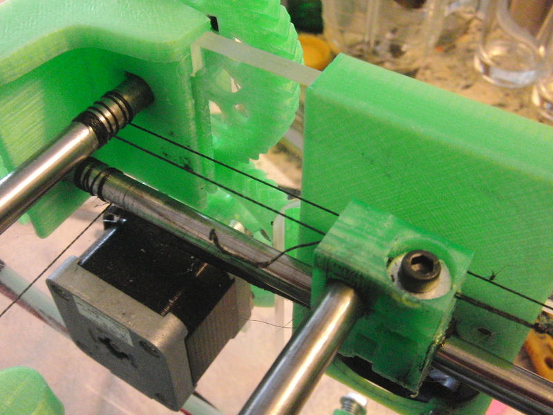
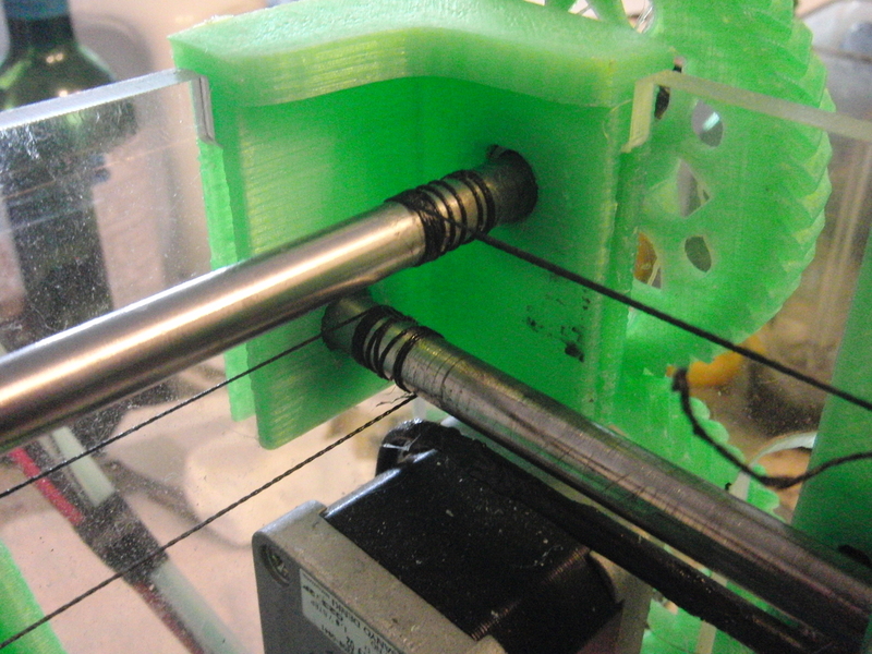
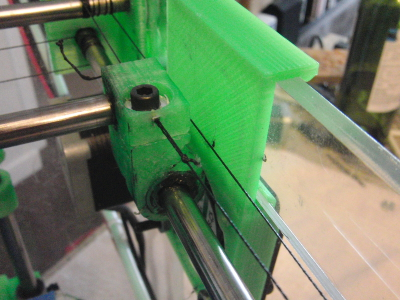
This is how the cable on the drive rods with the holes should look ideally (does not need to be perfect as long as it rolls on and rolls off).
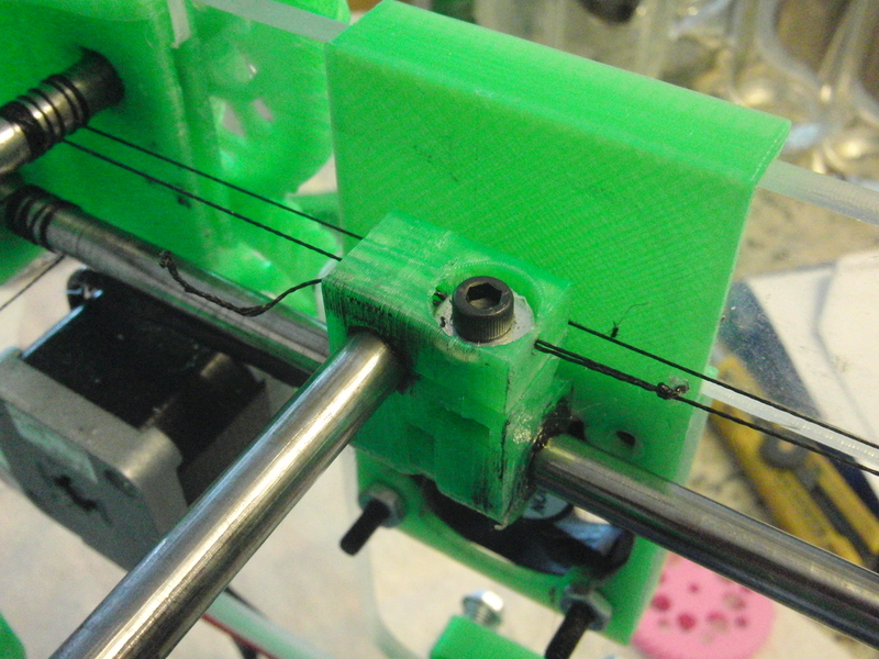
This is where the cables end and are tensioned.
This is how well the cable should line up with the XYend if done perfectly (do not worry if it is not perfect yet, it will move on its own to align properly).
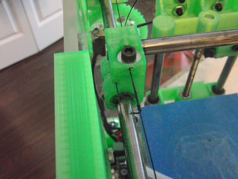
Sometimes the cable will run really close to the XYend and even touch.
Sometimes it will be far away from the XYend. Either way is fine we just don't want the cable to rub on the end of the metal rod in the XYend.
Edited 2 time(s). Last edit at 08/12/2012 09:29PM by Sublime.
It is very difficult to photograph the cables.
First off lets get the video out of the way, excuse the noise the mic was really close to the gears, motors and bearings.
This is how the cable on the drive rods with the holes should look ideally (does not need to be perfect as long as it rolls on and rolls off).


This is where the cables end and are tensioned.

This is how well the cable should line up with the XYend if done perfectly (do not worry if it is not perfect yet, it will move on its own to align properly).

Sometimes the cable will run really close to the XYend and even touch.

Sometimes it will be far away from the XYend. Either way is fine we just don't want the cable to rub on the end of the metal rod in the XYend.

Edited 2 time(s). Last edit at 08/12/2012 09:29PM by Sublime.
| FFF Settings Calculator | Gcode post processors | Geometric Object Deposition Tool Blog |
| Tantillus.org | Mini Printable Lathe | How NOT to install a Pololu driver |
Attachments:
open | download - Drive_cable_01.JPG (466.8 KB)
open | download - Drive_cable_02.JPG (460.4 KB)
open | download - Drive_cable_03.JPG (460.9 KB)
open | download - Cable_alignment.JPG (413.2 KB)
open | download - Cable_close_to_XYend.JPG (455 KB)
open | download - Cable_far_from_XYend.JPG (442.6 KB)
open | download - Drive_cable_01.JPG (466.8 KB)
open | download - Drive_cable_02.JPG (460.4 KB)
open | download - Drive_cable_03.JPG (460.9 KB)
open | download - Cable_alignment.JPG (413.2 KB)
open | download - Cable_close_to_XYend.JPG (455 KB)
open | download - Cable_far_from_XYend.JPG (442.6 KB)
|
Re: Early stages of build August 12, 2012 09:39PM |
Registered: 13 years ago Posts: 2,947 |
Lisa M Wrote:
-------------------------------------------------------
Let me answer the question directly now.
> "Taking the remainder of the long cable, run it
> behind the XY end to the opposing 5/16" by 212mm
> rod and proceed to wrap it around the rod 5 to 10
> times."
First I should say that the 212 is from the original prototype and they now use 210mm rods (fixing on the site now).
> 1.) What direction do I wrap the long end in on
> the opposing 212 bar?
We want the cables to run level from front to back / side to side. this means if the cable comes off the top of the first rod it then starts on the top of the opposing rod. And if it comes off the first rod from the bottom we want it to start on the opposing rod from the bottom.
>
> Other questions:
> 2.) Does it go in the groove of the XY on the
> adjacent 212?
The long piece of cable goes past the notch in the XY on its way to the opposing rod as picture above in the last two pictures. Then the two loose ends are joined at the center under the washer on the XYend.
> 3.) What does the cable do?
The cable turns the rotating motion of the shaft into linear motion for the print head.
>
> Earlier questions because I'm still not sure I
> wrapped it correctly:
>
> 4.) When you say for the upper bar to wrap it 5
> times clockwise, do you mean the direction of the
> cable should be wrapped clockwise or do you mean
> to spin the rod in a clockwise direction so the
> cable actually gets spun on in a counter-clockwise
> direction? I assumed the former and went with
> that but the long end of the cable coming off the
> bar is lower than the groove on the XY of the
> adjacent 212 instead of being directly in line
> with it. I'm not sure that is correct and I can't
> find a clear image of the cable anywhere on the
> tantillus site.
Yes the cable has to be wrapped around the bars. If you turn the rod it will wrap one end of the cable while unwrapping the other which is how the machine works but does not help to install the cable.
I will try and get the video of me doing this right away. It is getting dark now and I am losing light to film so it may not be until tomorrow I can get the video up. The rest of the pictures should be up tonight sometime (it may be 5am).
| FFF Settings Calculator | Gcode post processors | Geometric Object Deposition Tool Blog |
| Tantillus.org | Mini Printable Lathe | How NOT to install a Pololu driver |
|
Re: Early stages of build August 13, 2012 01:34AM |
Registered: 11 years ago Posts: 116 |
Sublime Wrote:
> First I should say that the 212 is from the
> original prototype and they now use 210mm rods
> (fixing on the site now).
I figured that one out
Thanks for the videos and images. That helps immensely. I didn't figure out the notch that the cable runs through and that was key. Also seeing how the cable runs back and forth is very helpful.
What type of cable is that? Does it ware out often? How would I get more?
Thanks again,
Lisa
|
Re: Early stages of build August 13, 2012 01:45AM |
Registered: 13 years ago Posts: 2,947 |
Lisa M Wrote:
-------------------------------------------------------
> What type of cable is that? Does it ware out
> often? How would I get more?
Its Bass Pro brand spectra braided fishing line. You can get it at most stores that sell fishing gear and online. I assume you can use any brand braided spectra fibre fishing line but have only used the Bass Pro brand so far. It is 65lb test rated line. You can read a little more about it on my blog
As for wear and tear I have not broken or worn out any of it yet and I have run three machine for the past month almost 24hrs a day plus the time they had been run before that. The only way I have ruined one is with an open flame while shrink wrapping the wires on the hotend.
Your kit included enough to replace it many times before having to buy more.
| FFF Settings Calculator | Gcode post processors | Geometric Object Deposition Tool Blog |
| Tantillus.org | Mini Printable Lathe | How NOT to install a Pololu driver |
|
Re: Early stages of build August 13, 2012 04:52PM |
Registered: 11 years ago Posts: 116 |
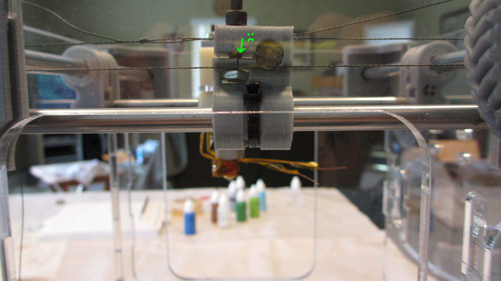
"Frack! Seriously?!?" were the words mumbled a few minutes earlier when this happened...
I got the cable figured out from the videos and pictures. Thank you! It was very helpful.
However I couldn't feed the cable under the washer so I had to pull the bolt and washer out. When I went to screw the bolt back in, the nut had shifted. I barely applied any pressure ...and the xy end cracked.
Please note this is not the XY that I cracked earlier. I marked that one so I could tell which one it was. This now the second XY that I've cracked.
I'm not sure I can fix this one but I'll try.
Edited 1 time(s). Last edit at 08/13/2012 04:56PM by Lisa M.
|
Re: Early stages of build August 13, 2012 05:38PM |
Registered: 11 years ago Posts: 116 |
|
Re: Early stages of build August 13, 2012 09:57PM |
Registered: 13 years ago Posts: 2,947 |
I will get you a new set don't worry.
| FFF Settings Calculator | Gcode post processors | Geometric Object Deposition Tool Blog |
| Tantillus.org | Mini Printable Lathe | How NOT to install a Pololu driver |
|
Re: Early stages of build August 14, 2012 04:35PM |
Registered: 11 years ago Posts: 116 |
Coming along...
Edited 1 time(s). Last edit at 08/14/2012 04:37PM by Lisa M.


Edited 1 time(s). Last edit at 08/14/2012 04:37PM by Lisa M.
|
Re: Early stages of build August 15, 2012 03:55PM |
Registered: 11 years ago Posts: 116 |
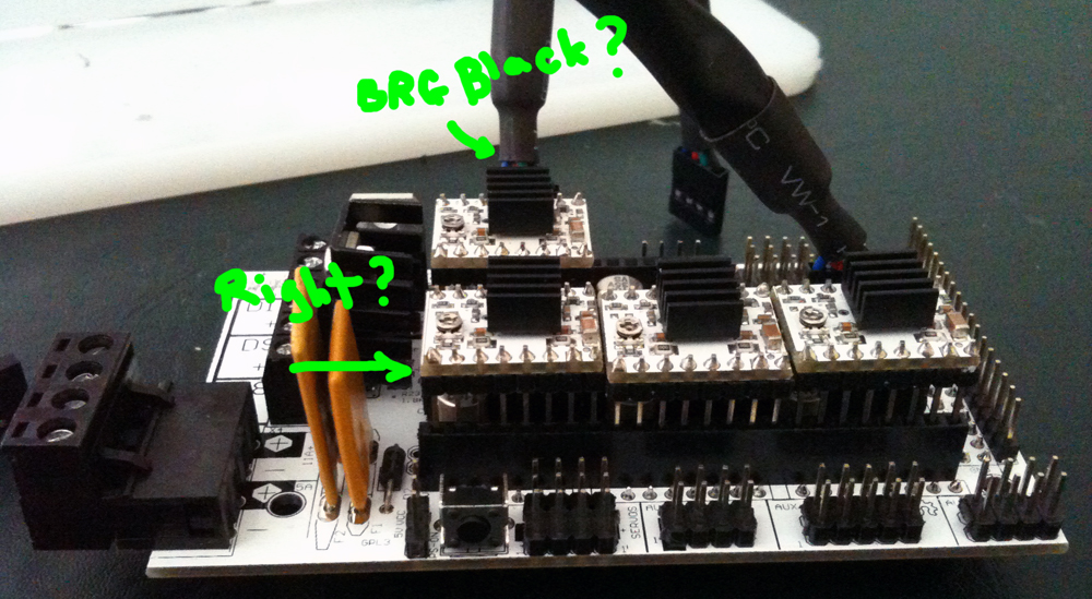
I'm the step where it says "Install four step stick drivers in the sockets on the RAMPS board for X, Y, Z and E0. See the RAMPS wiki page for orientation"
...but the RAMPS wiki page is greek to me and I can't find the part where I would see the "orientation"
I'm not ever sure what a "step stick driver" is and which of the little pieces of silicone in front of me might be that.
Any chance you could send me a picture of this.
...but the RAMPS wiki page is greek to me and I can't find the part where I would see the "orientation"
I'm not ever sure what a "step stick driver" is and which of the little pieces of silicone in front of me might be that.
Any chance you could send me a picture of this.
|
Re: Early stages of build August 15, 2012 04:55PM |
Registered: 11 years ago Posts: 116 |

|
Re: Early stages of build August 15, 2012 05:07PM |
Registered: 13 years ago Posts: 2,947 |
Nope those are all backwards the little dial (potentiometer) needs to be on the right when viewed from this side. I will add a picture to make it easier.
| FFF Settings Calculator | Gcode post processors | Geometric Object Deposition Tool Blog |
| Tantillus.org | Mini Printable Lathe | How NOT to install a Pololu driver |
|
Re: Early stages of build August 15, 2012 05:19PM |
Admin Registered: 17 years ago Posts: 7,879 |
Lisa,
Do the larger resistors each side of the heatsink have 000 marked on them? They should be 050 but samples I received seem to be zero ohm links.
[www.hydraraptor.blogspot.com]
Do the larger resistors each side of the heatsink have 000 marked on them? They should be 050 but samples I received seem to be zero ohm links.
[www.hydraraptor.blogspot.com]
|
Re: Early stages of build August 15, 2012 05:22PM |
Registered: 11 years ago Posts: 116 |
|
Re: Early stages of build August 15, 2012 05:25PM |
Registered: 11 years ago Posts: 116 |
|
Re: Early stages of build August 15, 2012 05:26PM |
Registered: 13 years ago Posts: 2,947 |
@ Nophead
I can answer. The ones I have here and I am using all have the two marked 000. I have not had a problem with them like this.
May I ask what type of problem this could cause?
I can answer. The ones I have here and I am using all have the two marked 000. I have not had a problem with them like this.
May I ask what type of problem this could cause?
| FFF Settings Calculator | Gcode post processors | Geometric Object Deposition Tool Blog |
| Tantillus.org | Mini Printable Lathe | How NOT to install a Pololu driver |
|
Re: Early stages of build August 15, 2012 06:03PM |
Admin Registered: 17 years ago Posts: 7,879 |
The current would be all or nothing. I had a Melzi with 0.005 fitted and it would immediately overheat unless the pot was set to almost 0.
[www.hydraraptor.blogspot.com]
[www.hydraraptor.blogspot.com]
|
Re: Early stages of build August 15, 2012 06:05PM |
Registered: 11 years ago Posts: 116 |
|
Re: Early stages of build August 15, 2012 06:20PM |
Registered: 13 years ago Posts: 2,947 |
Lisa M Wrote:
-------------------------------------------------------
> @sublime
>
> Do I have the motor connector oriented correctly
> in my picture?
>
> Blue 2B
> Red 2A
> Green 1A
> Black 1B
>
> ...or does that even matter?
Having them plugged in backwards will make the motors run backwards. So once you have the machine running you will test them and if the axis move the wrong direction you will UNPLUG the machine and then unplug the motor and plug it in the opposite direction. NEVER UNPLUG THE MOTOR OR DRIVER WITH THE MACHINE PLUGGED IN.
| FFF Settings Calculator | Gcode post processors | Geometric Object Deposition Tool Blog |
| Tantillus.org | Mini Printable Lathe | How NOT to install a Pololu driver |
|
Re: Early stages of build August 17, 2012 10:41PM |
Registered: 11 years ago Posts: 116 |
|
Re: Early stages of build August 17, 2012 10:46PM |
Registered: 11 years ago Posts: 939 |
|
Re: Early stages of build August 18, 2012 12:42AM |
Registered: 11 years ago Posts: 116 |

|
Re: Early stages of build August 18, 2012 01:59AM |
Registered: 11 years ago Posts: 116 |
Darn. I could move the xyz... and the fans turned on ...and it looked like everything was gonna work
But then the pronterface window did this when I tried to connect this time:
Connecting...
~†ø~˜€fæàžþž˜˜~f†ø†žž
I'm pretty sure that's not good.
I've unplugged the beast and am backing away slowly now.
Gonna go find a piece of low tech ...a book ...yah ...something to escape into for a while before bed.
I'm signing out for a few days ...off the grid. Hope everyone's builds go well ...and maybe I'll see some of you at the local build day.
Thanks for all the help.
Lisa
|
Re: Early stages of build August 18, 2012 03:59AM |
Admin Registered: 17 years ago Posts: 7,879 |
|
Re: Early stages of build August 18, 2012 08:23AM |
Registered: 13 years ago Posts: 2,947 |
Yes I have the baud rate set at 115200 (not 250000) to ensure that it works with all systems. I had trouble with my Sanguinololu at 250000 and my Arduino 1280 at 250000 and since we can print from SD we do not need the faster USB communication. I have fixed the instructions.
| FFF Settings Calculator | Gcode post processors | Geometric Object Deposition Tool Blog |
| Tantillus.org | Mini Printable Lathe | How NOT to install a Pololu driver |

Sorry, only registered users may post in this forum.