Eric's Tantillus build
Posted by Eric Young
|
Re: Eric's Tantillus build August 25, 2012 04:49PM |
Registered: 13 years ago Posts: 2,947 |
Looks good.
A few questions / tips:
1) Did you use the calibration configs I provided last night?
2) I assume you used your own cube to test as the one I provided was 20x20x10.
3) The layers curling may indicate that the default fan speed may need to be increased by a little in the firmware.
4) The rough(ish) surface finish is a result of the cables not being as tight as possible but also the fact I have z-lift enabled in the normal profiles. I would leave it for now and do some more test prints and then try and tighten the cables a little more.
5) The infill looks perfect. Did you have to calibrate it at all or was my default just right?
6) I assume the last picture is of the first layer. If so I think it may be a little to high. Try lowering it 0.05.
| FFF Settings Calculator | Gcode post processors | Geometric Object Deposition Tool Blog |
| Tantillus.org | Mini Printable Lathe | How NOT to install a Pololu driver |
|
Re: Eric's Tantillus build August 25, 2012 05:32PM |
Registered: 11 years ago Posts: 149 |
Thanks all 
Sublime Wrote:
-------------------------------------------------------
> 1) Did you use the calibration configs I provided
> last night?
> 2) I assume you used your own cube to test as the
> one I provided was 20x20x10.
Yup I did use my own cube. As for the calibration I just loaded your 'Standard (0.5mm)_Default' configuration, set the 'fill density' to 1, and then toyed with the Z-offset in .05 increments until it worked.
> 3) The layers curling may indicate that the
> default fan speed may need to be increased by a
> little in the firmware.
Cool, approximately how much is a little?
> 4) The rough(ish) surface finish is a result of
> the cables not being as tight as possible but also
> the fact I have z-lift enabled in the normal
> profiles. I would leave it for now and do some
> more test prints and then try and tighten the
> cables a little more.
You called it - my cables are not as tight as they could be. I was having a hard time keeping the XY axis square when I made the cables super tight, so I loosened them up a little. I'm doing some more prints as we speak and they're looking decent. The bottom 1.5mm or so of each print so far today is having a hard time, but after that the parts start to look good.
> 5) The infill looks perfect. Did you have to
> calibrate it at all or was my default just right?
As mentioned above the only thing I changed in your settings was 'fill density' to 1 instead of the .4 default. Easy cheesy
> 6) I assume the last picture is of the first
> layer. If so I think it may be a little to high.
> Try lowering it 0.05.
Yup. When you say lower it, do you mean raise the bed? Sorry I'm still trying to wrap my head around these orientations/terminologies.
|
Re: Eric's Tantillus build August 25, 2012 06:09PM |
Registered: 13 years ago Posts: 2,947 |
Eric Young Wrote:
-------------------------------------------------------
> > 3) The layers curling may indicate that the
> > default fan speed may need to be increased by a
> > little in the firmware.
>
> Cool, approximately how much is a little?
Good question. In the configuraton.h file you will find:
#define AUTO_FAN_MIN 150 // Minimum speed to keep the fan at (value 0 - 255) (comment out if not in use)
Try increasing the fan speed by 25 at a time until it seems to stop the curling or gets to noisy. You can also increase it in slic3r under the cooling tab. Only increase the one in slic3r by 5 at a time as it is a percentage where the firmware is a division of 255.
>
> > 4) The rough(ish) surface finish is a result of
> > the cables not being as tight as possible but
> also
> > the fact I have z-lift enabled in the normal
> > profiles. I would leave it for now and do some
> > more test prints and then try and tighten the
> > cables a little more.
>
> You called it - my cables are not as tight as they
> could be. I was having a hard time keeping the XY
> axis square when I made the cables super tight, so
> I loosened them up a little. I'm doing some more
> prints as we speak and they're looking decent. The
> bottom 1.5mm or so of each print so far today is
> having a hard time, but after that the parts start
> to look good.
I am working on this part of the instructions and should have something for you soon.
>
> > 5) The infill looks perfect. Did you have to
> > calibrate it at all or was my default just
> right?
>
> As mentioned above the only thing I changed in
> your settings was 'fill density' to 1 instead of
> the .4 default. Easy cheesy
That is great to hear.
>
> > 6) I assume the last picture is of the first
> > layer. If so I think it may be a little to
> high.
> > Try lowering it 0.05.
>
> Yup. When you say lower it, do you mean raise the
> bed? Sorry I'm still trying to wrap my head around
> these orientations/terminologies.
Well this one is tough and may always be confusing as we all see these things differently. I should have said you want to make the nozzle closer to the bed by 0.05
| FFF Settings Calculator | Gcode post processors | Geometric Object Deposition Tool Blog |
| Tantillus.org | Mini Printable Lathe | How NOT to install a Pololu driver |
|
Re: Eric's Tantillus build August 25, 2012 09:21PM |
Registered: 11 years ago Posts: 149 |
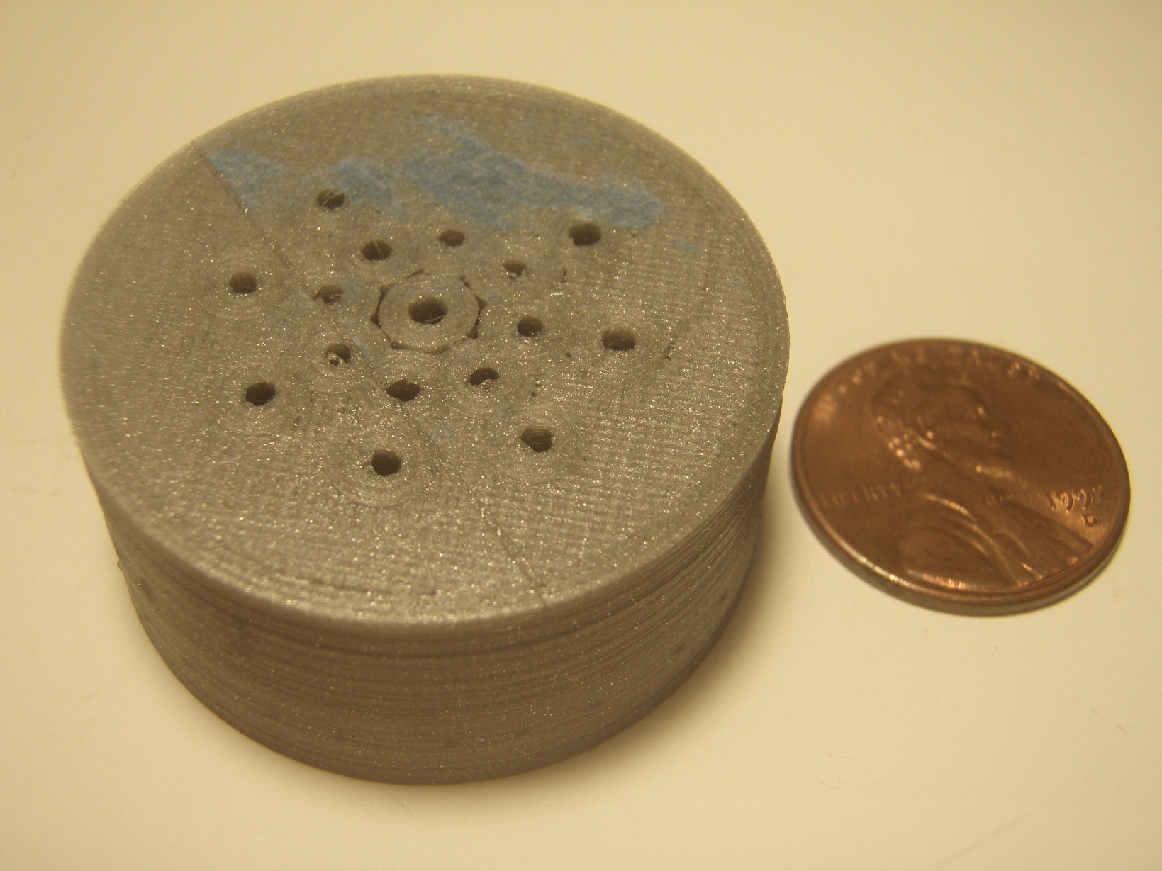
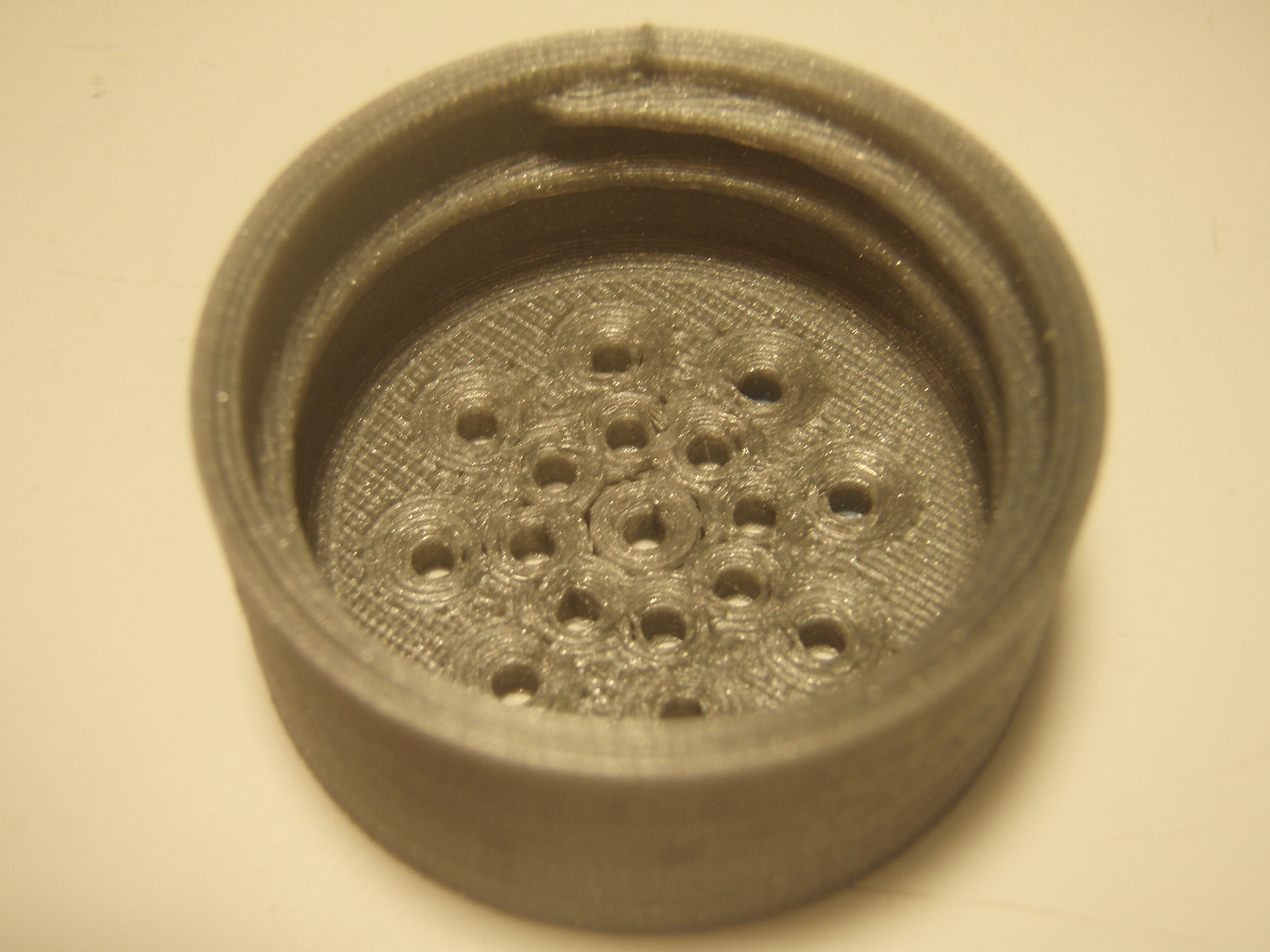
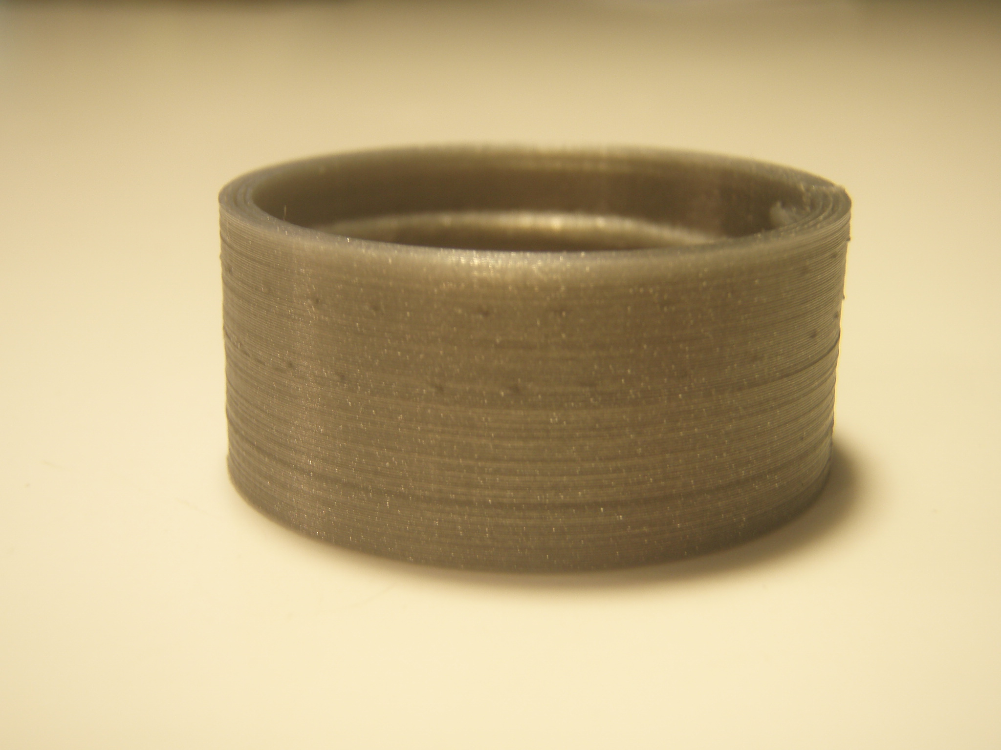
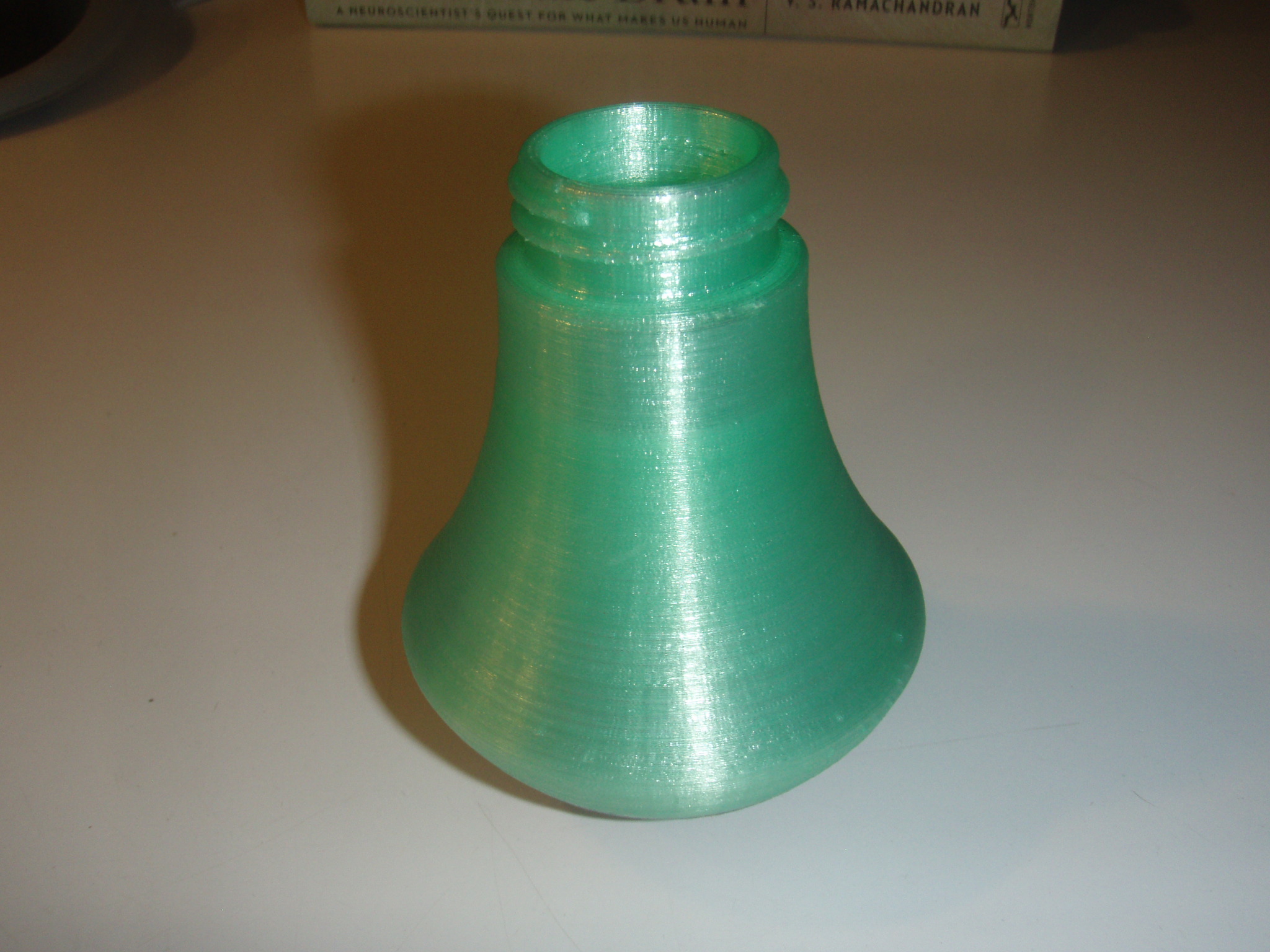
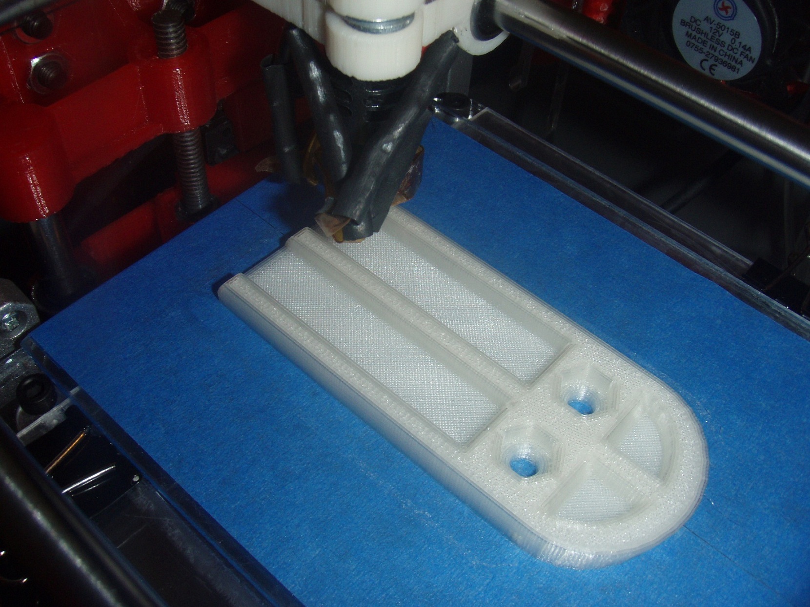
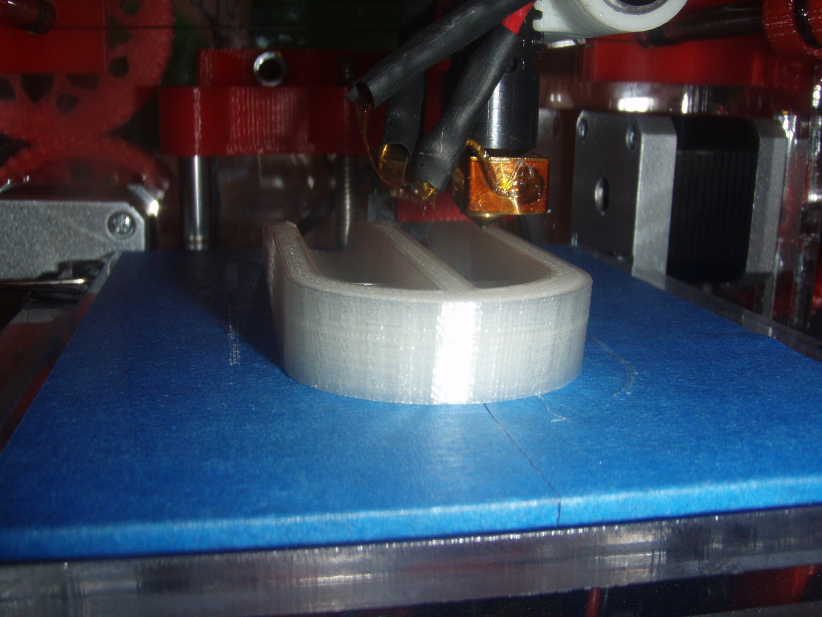
Changed the Z-offset by another .05 as you recommended and halved the bottom layer speed to get a really nice result - see first 3 attached pics. The part is a threaded cap and the threads turned out really nicely shaped. I think they may need to be painted with some adhesive epoxy type stuff to toughen them up a bit. No cleanup was done to it.
Haven't seen the layer peeling issue since the first run so have yet to try changing the fan speed.
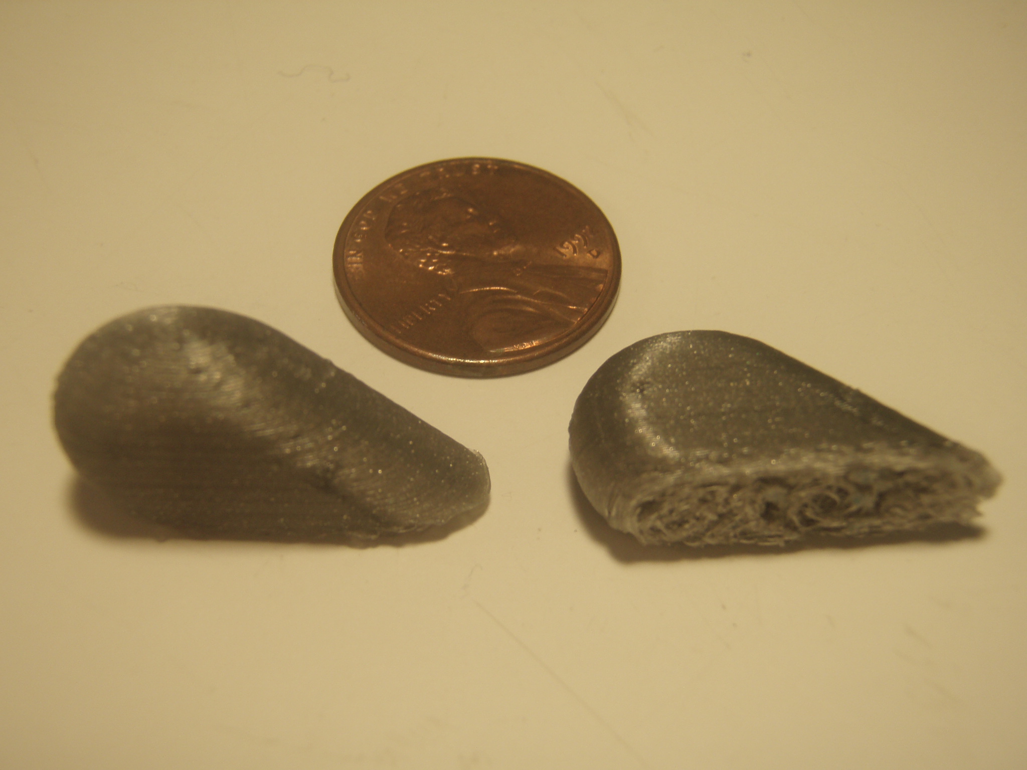
The other close up pic is of a couple heart pendant pieces that I tried earlier today - these are the parts that had the problem with the bottom 1.5mm. I'll give them another shot with the new offset - they only take like 15 minutes each with 100% infill
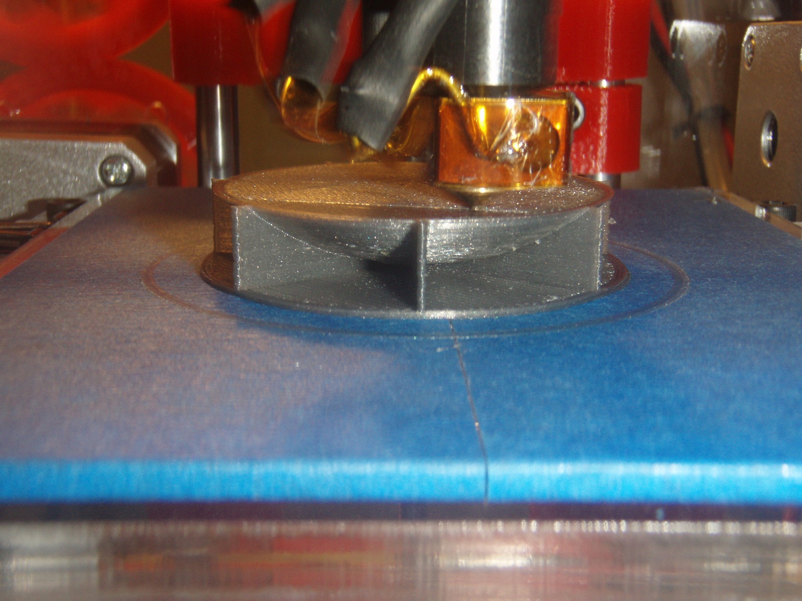
The last couple pics are of a part that''s running now - it has some support structures and is supposed to be 3.5 inches (about 90mm) tall, so it will be very interesting to see how it does, though I think I'm going to run out of filament before it ends
Edited 2 time(s). Last edit at 08/25/2012 09:23PM by Eric Young.
- see first 3 attached pics. The part is a threaded cap and the threads turned out really nicely shaped. I think they may need to be painted with some adhesive epoxy type stuff to toughen them up a bit. No cleanup was done to it.Haven't seen the layer peeling issue since the first run so have yet to try changing the fan speed.
The other close up pic is of a couple heart pendant pieces that I tried earlier today - these are the parts that had the problem with the bottom 1.5mm. I'll give them another shot with the new offset - they only take like 15 minutes each with 100% infill
The last couple pics are of a part that''s running now - it has some support structures and is supposed to be 3.5 inches (about 90mm) tall, so it will be very interesting to see how it does, though I think I'm going to run out of filament before it ends
Edited 2 time(s). Last edit at 08/25/2012 09:23PM by Eric Young.
|
Re: Eric's Tantillus build August 27, 2012 02:41AM |
Registered: 11 years ago Posts: 149 |
Day 2 of printing and the Tantillus continues to just kill it.
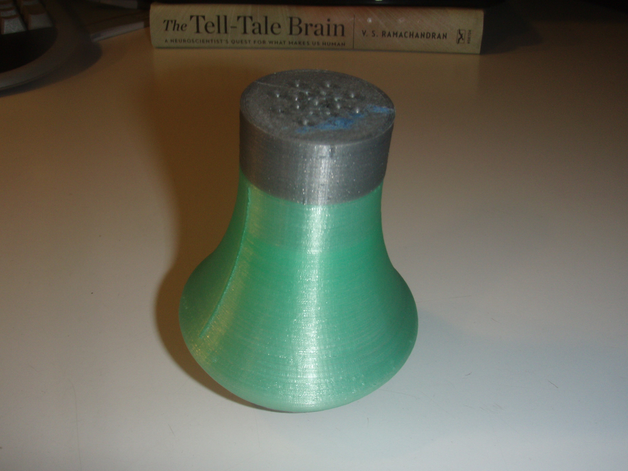
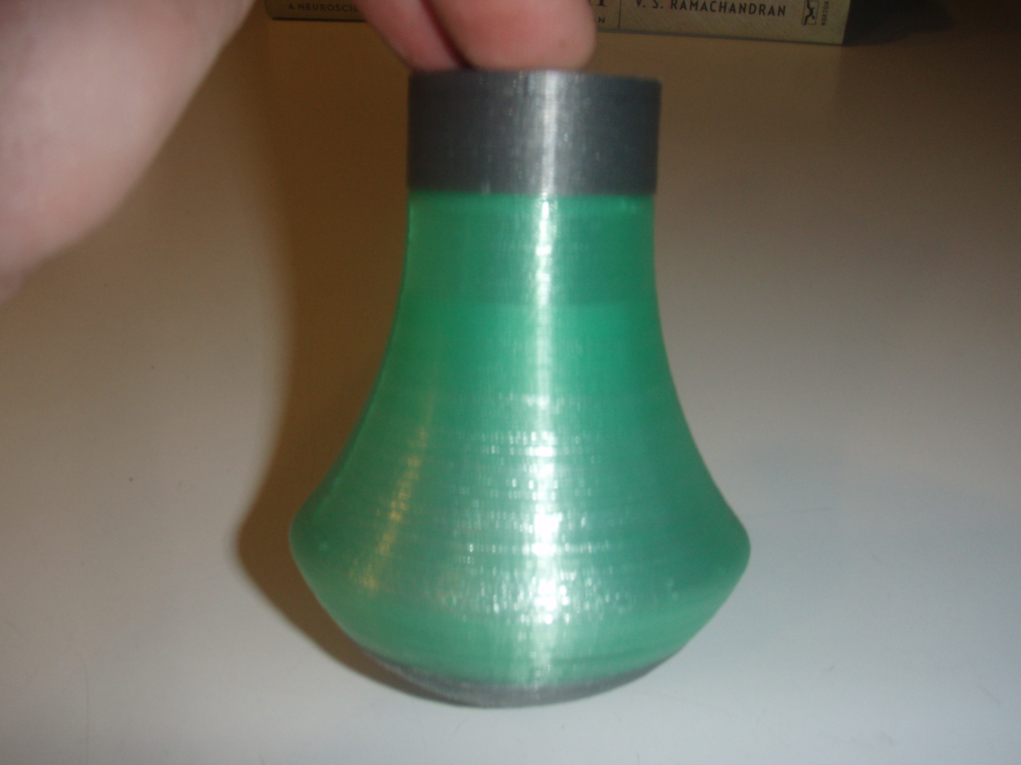
Pics are attached are for a big print - the green portion is 3 inch tall and max diameter is 2.725 inch by design. The printed part measures in at 2.721" on that max diameter and I forgot to measure the height before gluing it to the grey base so too late now. The threads are gorgeous and mate perfectly with the threads of the grey cap.
Only issue I had was a little backlash in the gears in one spot of the rotation where they don't mesh up perfectly. This bad-mesh spot happened to be in (or maybe wore the gears as a result of??) the same spot on the print where the hotend had a quick movement/direction change in order to finish one arc/circle and move on to the next concentric arc/circle of the layer it was printing. The result was the visible line going up the side of the green part. I'd guess all machines (of this FDM type) have the same issue where there is a direction change in the software, but my gear-mesh problem just made the line a bit more visible this time around.
|
Re: Eric's Tantillus build August 27, 2012 02:59AM |
Registered: 13 years ago Posts: 2,947 |
The print looks really nice and I am so glad to see the first printer in the wild printing that well. It tells me its not just my experience that makes mine print well.
For the play in the gears:
It is possible that one of the gears is not perfectly centered and can be corrected by loosening the set screw on one side and tightening the one on the other side.
It is possible that the gears had some surface imperfections that have now worn off and you can move the gears closer together.
It is possible that the gears are slightly out of round (doubtful as it took special care printing the gears) and they need to be tuned. To tune them you loosen the motor mounting bolts and lower the motor down just enough to turn the motor gear a few degrees and then remount the motor and test. For gears that are out of round you will find two spots where the out of round of one gear syncs with the out of round of the other gear.
| FFF Settings Calculator | Gcode post processors | Geometric Object Deposition Tool Blog |
| Tantillus.org | Mini Printable Lathe | How NOT to install a Pololu driver |
|
Re: Eric's Tantillus build August 27, 2012 03:01AM |
Registered: 13 years ago Posts: 2,947 |
Also the vertical line is the seam where the ends of the outer perimeter meet. It should not stick out but it will always be visible as a dark line or row of small pin holes.
| FFF Settings Calculator | Gcode post processors | Geometric Object Deposition Tool Blog |
| Tantillus.org | Mini Printable Lathe | How NOT to install a Pololu driver |
|
Re: Eric's Tantillus build August 27, 2012 07:15AM |
Registered: 11 years ago Posts: 51 |
|
Re: Eric's Tantillus build August 27, 2012 03:30PM |
Registered: 11 years ago Posts: 95 |
|
Re: Eric's Tantillus build August 29, 2012 03:27AM |
Registered: 11 years ago Posts: 149 |
Thanks for the hat tips guys
Sublime - Thank you for all your suggestions on the gears. I ended up spending some real quality time with them today and right now it's printing a spool holder that so far looks to be the best print to date on this machine
Since it's doing so well right now I figure maybe I should take a shot at printing some backup gears; does that sound reasonable at this point given I'm not too experienced with this yet? If so I'm wondering if you use any special settings or other tricks I should know of for gear printing? I have the .5 nozzle in right now.
Edit: Just in case anyone notices - those larger-sized facets on the semicircle of the spool holder part are actually in the STL model itself, so it's supposed to look a little squared off where it goes around that arc.
Edited 1 time(s). Last edit at 08/29/2012 03:34AM by Eric Young.
|
Re: Eric's Tantillus build August 29, 2012 03:42AM |
Registered: 13 years ago Posts: 2,947 |
We want the gears to be almost solid or completely solid. You can do this by setting the infill to 0.8 or higher. I must say though, I have never switched gears yet and my machines have hundreds of hours on them. Mine are starting to show signs of wear (white area on the gray gears and some noise as it does rapid narrow infill) but not enough to show up in the prints yet. If you do print an extra gear I recommend you follow the basic flow calibration first to ensure it is correct. After printing one gear confirm it fits on a motor or that the nut fits inside before printing an entire set.
| FFF Settings Calculator | Gcode post processors | Geometric Object Deposition Tool Blog |
| Tantillus.org | Mini Printable Lathe | How NOT to install a Pololu driver |
|
Re: Eric's Tantillus build August 29, 2012 01:53PM |
Registered: 11 years ago Posts: 149 |
Does anyone know if there has been any experimentation with heat packs to warm up a printer bed? I mean the type you take camping - there are some that are rechargeable if boiled in water and their temp hovers around 54 deg Celcius or 130 deg Farenheit when activated. I just had the random thought last night that if one of these could fit in between the top and bottom bed acrylic it could be worth a try. Any thoughts?
Link to heat pack description: [beneforce.com]
Link to heat pack description: [beneforce.com]
|
Re: Eric's Tantillus build August 29, 2012 03:51PM |
Registered: 13 years ago Posts: 2,947 |
The point of a heated bed is to keep as much of the object as possible just below the glass transition temperature so the entire thing can cool and shrink at the same time. With this said anything that can keep the PLA at or near 50c for most of the build will work. But we do not want the Z-arms to reach that temp so you need to make sure the heat goes up and not down.
| FFF Settings Calculator | Gcode post processors | Geometric Object Deposition Tool Blog |
| Tantillus.org | Mini Printable Lathe | How NOT to install a Pololu driver |
|
Re: Eric's Tantillus build August 29, 2012 04:20PM |
Admin Registered: 17 years ago Posts: 7,879 |
Sublime,
Do you put grease on your gears? It makes ABS extruder gears last many many times longer.
[www.hydraraptor.blogspot.com]
Do you put grease on your gears? It makes ABS extruder gears last many many times longer.
[www.hydraraptor.blogspot.com]
|
Re: Eric's Tantillus build August 29, 2012 04:41PM |
Registered: 13 years ago Posts: 2,947 |
nophead Wrote:
-------------------------------------------------------
> Sublime,
> Do you put grease on your gears? It makes ABS
> extruder gears last many many times longer.
I have on one machine to see if it made any difference and it made it a little quieter but I am not sure if it made them last longer. I will have to grease one set only on one machine and see if it lasts longer then the other set on that machine. Do you have a recommendation on the type of grease to use? I have just been using Vaseline because it is always around and safe around most stuff.
| FFF Settings Calculator | Gcode post processors | Geometric Object Deposition Tool Blog |
| Tantillus.org | Mini Printable Lathe | How NOT to install a Pololu driver |
|
Re: Eric's Tantillus build August 29, 2012 06:35PM |
Admin Registered: 17 years ago Posts: 7,879 |
|
Re: Eric's Tantillus build August 29, 2012 10:11PM |
Registered: 11 years ago Posts: 149 |
While in the middle of a print just now I heard a fairly loud pop come from my machine and looked back to see that nothing was moving. 99% sure it was electrical because I've heard similar pops before from short circuits.
I unplugged USB and wall power immediately and after plugging back into USB only the Arduino green and orange LEDs light up and the RAMPS green LED lights. Pulled off each Pololu and they all look fine. Visually I can't see anything that looks out of sorts on any board or cable connector.
Any suggestions or references I'd be able to use to figure this one out?
|
Re: Eric's Tantillus build August 29, 2012 10:55PM |
Registered: 13 years ago Posts: 2,947 |
I would start with the power supply and see if it is dead. If it works and has 15v then we need to move onto the Arduino voltage regulator and see if it is supplying 5 from the 15v input.
| FFF Settings Calculator | Gcode post processors | Geometric Object Deposition Tool Blog |
| Tantillus.org | Mini Printable Lathe | How NOT to install a Pololu driver |
|
Re: Eric's Tantillus build August 30, 2012 01:29AM |
Registered: 11 years ago Posts: 149 |
|
Re: Eric's Tantillus build August 30, 2012 01:30AM |
Registered: 13 years ago Posts: 2,947 |
|
Re: Eric's Tantillus build August 30, 2012 01:01PM |
Registered: 11 years ago Posts: 149 |
|
Re: Eric's Tantillus build August 31, 2012 01:02PM |
Registered: 11 years ago Posts: 149 |
|
Re: Eric's Tantillus build August 31, 2012 03:25PM |
Registered: 13 years ago Posts: 2,947 |
The voltage regulator on the Arduino is only rated to 19v and it is not recommended to go over 12v really. My 15v power supplies are already making the regulator heat up a little so I would not go higher then 15v. You can use a lower voltage unit without issue.
| FFF Settings Calculator | Gcode post processors | Geometric Object Deposition Tool Blog |
| Tantillus.org | Mini Printable Lathe | How NOT to install a Pololu driver |
|
Re: Eric's Tantillus build August 31, 2012 05:22PM |
Registered: 11 years ago Posts: 149 |
|
Re: Eric's Tantillus build August 31, 2012 05:42PM |
Registered: 13 years ago Posts: 2,947 |
I would not go below 12v. For amperage I have run them off of a 12v @ 5A power supply and had no problems.
| FFF Settings Calculator | Gcode post processors | Geometric Object Deposition Tool Blog |
| Tantillus.org | Mini Printable Lathe | How NOT to install a Pololu driver |
|
Re: Eric's Tantillus build September 13, 2012 02:51PM |
Registered: 11 years ago Posts: 149 |
Just burnt up a resistor (it was not foil wrapped). While trying to insert the second one, which is wrapped with foil this time, I had problems getting the foil to actually go into the hole along with the resistor. It kept bunching up on the outside of the hotend when I tried to push it in. Is there some trick to this other than just wrapping the foil as tight as possible? I did get a little bit of foil to squeeze in there on one try, but the fit still felt very loose.
Is there anything else I could use instead of foil? Maybe thermal paste or some other conductive, non-permanent adhesive or goopy type stuff to fill the air gap? WWFP linked his thermal paste (thanks WWFP), so I guess I'm wondering if anyone knows of some sort of inexpensive, 'readily available at the local electronics or hardware store' type of paste?
Is there anything else I could use instead of foil? Maybe thermal paste or some other conductive, non-permanent adhesive or goopy type stuff to fill the air gap? WWFP linked his thermal paste (thanks WWFP), so I guess I'm wondering if anyone knows of some sort of inexpensive, 'readily available at the local electronics or hardware store' type of paste?
|
Re: Eric's Tantillus build September 13, 2012 03:04PM |
Registered: 13 years ago Posts: 2,947 |
No secret to installing the foil, just a fight. You can use muffler cement from an automotive store. It is similar to fire cement but a little weaker and can be removed without needing to drill out the resistor. You can also use thermal adhesive like Arctic Silver (for computers) but you will have to drill out the resistor if it fails. In the past I have used tin foil with a small drop of thermal compound on it and it did seem to work but was messy. But if your resistor is fairly straight (not peanut shaped) and fits well it may not need anything. I have a couple that needed the foil and some that did not.
| FFF Settings Calculator | Gcode post processors | Geometric Object Deposition Tool Blog |
| Tantillus.org | Mini Printable Lathe | How NOT to install a Pololu driver |
|
Re: Eric's Tantillus build September 13, 2012 03:12PM |
Registered: 11 years ago Posts: 149 |
Thanks Sublime - this second resistor I have is more peanut-shaped than the first, so I think I'll try a couple of your suggestions.
What do you think about using muffler cement to coat the resitor just a bit and then letting it dry before inserting it? this way it could be sanded down to the proper size (I'd think).
What do you think about using muffler cement to coat the resitor just a bit and then letting it dry before inserting it? this way it could be sanded down to the proper size (I'd think).
|
Re: Eric's Tantillus build September 13, 2012 03:17PM |
Registered: 13 years ago Posts: 2,947 |
Eric Young Wrote:
-------------------------------------------------------
> Thanks Sublime - this second resistor I have is
> more peanut-shaped than the first, so I think I'll
> try a couple of your suggestions.
>
> What do you think about using muffler cement to
> coat the resitor just a bit and then letting it
> dry before inserting it? this way it could be
> sanded down to the proper size (I'd think).
It could work but you would have to be careful. The resistor is a coil of nichrome wire that has been coated in ceramic and the nichrome can be very close to the surface which means you could sand off enough coating that it can short out against the brass block.
| FFF Settings Calculator | Gcode post processors | Geometric Object Deposition Tool Blog |
| Tantillus.org | Mini Printable Lathe | How NOT to install a Pololu driver |
|
Re: Eric's Tantillus build September 13, 2012 03:23PM |
Registered: 11 years ago Posts: 149 |


Sorry, only registered users may post in this forum.