PxT's Tantillus build
Posted by PxT
|
PxT's Tantillus build September 25, 2012 10:31PM |
Registered: 11 years ago Posts: 16 |
I'm progressing along with my build pretty well so I figured I would start a thread to track my progress, and hopefully get a few hints along the way.
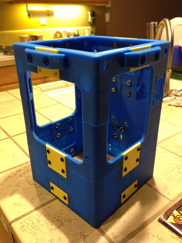
I have now printed the entire case twice. The first time my calibration was slightly off, causing all the parts to be stretched vertically by a small amount. Unfortunately I didn't inspect the parts closely enough as they were printing and I didn't catch it until all 12 pieces were done. So that was about 36 hours of printing wasted.
Just finished up the second go round and things are fitting together a bit better this time:
Are there any build instructions anywhere for the printed case? The tantillus.org build guide only seems to cover the laser-cut case and I'm not sure that I got all the bolts right. For example, which ones need washers and which ones don't? For the vertical (corner) connectors, which size bolts should I be using there? I have all these unmarked bags of bolts, nuts and washers and I'm confusing myself a bit. Which size bolts are used for the lower two holes on the top rear and top front connectors? I thought it would be the 10-32 1/4 but the BOM only has 22 listed and I have used them all already on the other connectors.
Edited 1 time(s). Last edit at 09/25/2012 10:35PM by PxT.
|
Re: PxT's Tantillus build September 25, 2012 11:02PM |
Registered: 13 years ago Posts: 2,947 |
PxT Wrote:
-------------------------------------------------------
> Are there any build instructions anywhere for the
> printed case?
Not really, I have asked anyone assembling one to document it and put it on the Wiki.
The tantillus.org build guide only
> seems to cover the laser-cut case and I'm not sure
> that I got all the bolts right. For example,
> which ones need washers and which ones don't?
The only washers on the printed case are the ones that are used to adjust the force applied by the stiffeners.
For
> the vertical (corner) connectors, which size bolts
> should I be using there?
I believe those may be missing. I think someone else that built the printed case mentioned it and I forgot until now. Maybe they will speak up and let us know.
Which size bolts are used
> for the lower two holes on the top rear and top
> front connectors? I thought it would be the 10-32
> 1/4 but the BOM only has 22 listed and I have used
> them all already on the other connectors.
You used them to hold the right side connector on which is actually supposed to have #10x3/4" because they hold the extruder on as well.
| FFF Settings Calculator | Gcode post processors | Geometric Object Deposition Tool Blog |
| Tantillus.org | Mini Printable Lathe | How NOT to install a Pololu driver |
|
Re: PxT's Tantillus build September 26, 2012 12:10AM |
Registered: 11 years ago Posts: 16 |
|
Re: PxT's Tantillus build September 26, 2012 12:16AM |
Registered: 11 years ago Posts: 16 |
Sublime Wrote:
>> For the vertical (corner) connectors, which size
>> bolts should I be using there?
>
> I believe those may be missing. I think someone
> else that built the printed case mentioned it and
> I forgot until now. Maybe they will speak up and
> let us know.
Looks like you have answered it already here:
[forums.reprap.org]
> You used them to hold the right side connector on
> which is actually supposed to have #10x3/4"
> because they hold the extruder on as well.
Ok, thanks.
|
Re: PxT's Tantillus build September 26, 2012 12:31AM |
Registered: 13 years ago Posts: 2,947 |
High infill (80-100%) on:
Carriage parts.
Gears.
Extruder parts.
XYends.
Z-coupler.
Normal infill on the rest. I use 25%
Carriage parts.
Gears.
Extruder parts.
XYends.
Z-coupler.
Normal infill on the rest. I use 25%
| FFF Settings Calculator | Gcode post processors | Geometric Object Deposition Tool Blog |
| Tantillus.org | Mini Printable Lathe | How NOT to install a Pololu driver |
|
Re: PxT's Tantillus build September 26, 2012 01:04AM |
Registered: 12 years ago Posts: 195 |
Way to go! I'm glad to see someone else building a printed case Tantillus. Good color scheme too...
I'd updated the printed case section on the wiki a while back to cover a few issues I had. Please take a look at that as well as my build log thread in this forum for some tips.
The printed build is surprisingly similar to the laser cut build with the exceptions being the extruder mounting, fan mounts, XY 5/16" rod lengths, electronics mounting (will add to the wiki when I finish), potentially an offset in drilling the lower platform (see wiki), and of course less clearance for stringing the cable.
|
Re: PxT's Tantillus build September 26, 2012 01:24AM |
Registered: 11 years ago Posts: 16 |
|
Re: PxT's Tantillus build September 26, 2012 01:54AM |
Registered: 13 years ago Posts: 2,947 |
PxT Wrote:
-------------------------------------------------------
> Just noticed that there doesn't seem to be a
> provision for mounting the LCD/encoder on the
> printed case (no cutout window as found on the
> acrylic case). Kinda bummed, I really want the
> LCD. Any reason this wasn't designed into the
> plastic version?
It won't really fit correctly in the printed case because of having it split. The idea I had was to make a plate that bolted to the front using four of the bolts on the front connector. I did cut an opening in my printed machine for the LCD but it intersects the seam in the middle and I had to glue it in.
| FFF Settings Calculator | Gcode post processors | Geometric Object Deposition Tool Blog |
| Tantillus.org | Mini Printable Lathe | How NOT to install a Pololu driver |
|
Re: PxT's Tantillus build September 27, 2012 03:17PM |
Registered: 12 years ago Posts: 195 |
Sublime Wrote:
-------------------------------------------------------
> PxT Wrote:
> --------------------------------------------------
> -----
> For
> > the vertical (corner) connectors, which size
> bolts
> > should I be using there?
>
> I believe those may be missing. I think someone
> else that built the printed case mentioned it and
> I forgot until now. Maybe they will speak up and
> let us know.
Forgot to answer this earlier...
IIRC you'd mentioned that those were vestiges of a design intended to be printed on a 200x200mm platform where the parts joined vertically and didn't have horizontal connectors, right?
I found that a #10 bolt (can't remember the length I used) will barely fit in that hole, and aligns the top and mid corners which otherwise sit a few mm off in my build. Zip ties might work too. This isn't supposed to be necessary, but I feel safer picking the printer up by the top part with the screws there as the only other support between the top and mid is one connector.
|
Re: PxT's Tantillus build September 27, 2012 03:42PM |
Registered: 13 years ago Posts: 2,947 |
pokey9000 Wrote:
-------------------------------------------------------
> Sublime Wrote:
> --------------------------------------------------
> -----
> > PxT Wrote:
> >
> --------------------------------------------------
>
> > -----
> > For
> > > the vertical (corner) connectors, which size
> > bolts
> > > should I be using there?
> >
> > I believe those may be missing. I think someone
> > else that built the printed case mentioned it
> and
> > I forgot until now. Maybe they will speak up
> and
> > let us know.
>
> Forgot to answer this earlier...
>
> IIRC you'd mentioned that those were vestiges of a
> design intended to be printed on a 200x200mm
> platform where the parts joined vertically and
> didn't have horizontal connectors, right?
Yes and no. All of them except the two in the front posts are from the 3 piece 200 x 200 design. But the two in the front two post are needed since they are the only way of connecting the posts together.
| FFF Settings Calculator | Gcode post processors | Geometric Object Deposition Tool Blog |
| Tantillus.org | Mini Printable Lathe | How NOT to install a Pololu driver |
|
Re: PxT's Tantillus build September 27, 2012 06:02PM |
Registered: 12 years ago Posts: 195 |
Sublime Wrote:
-------------------------------------------------------
> Yes and no. All of them except the two in the
> front posts are from the 3 piece 200 x 200 design.
> But the two in the front two post are needed since
> they are the only way of connecting the posts
> together.
Ok, sorry I wasn't clear on that. Wiki'd.
|
Re: PxT's Tantillus build September 29, 2012 08:50PM |
Registered: 11 years ago Posts: 16 |
|
Re: PxT's Tantillus build September 29, 2012 09:44PM |
Registered: 13 years ago Posts: 2,947 |
Check out the SVG or DXF called All_panels in the laser cut case files. It includes the Bed parts. The dimensions are a result of the window cutouts in the laser cut case
| FFF Settings Calculator | Gcode post processors | Geometric Object Deposition Tool Blog |
| Tantillus.org | Mini Printable Lathe | How NOT to install a Pololu driver |
|
Re: PxT's Tantillus build September 30, 2012 12:48PM |
Registered: 11 years ago Posts: 16 |
Forgive my ignorance, but how do I use those files to get the exact dimensions? How thick should the material be? I can cut something out of acrylic or plywood on my table saw and drill the appropriate holes but I'm not sure how to proceed just based on those files. I guess I could assemble everything else and measure based on that but it seems like the dimensions should be available as a reference as well. Thanks
|
Re: PxT's Tantillus build September 30, 2012 01:35PM |
Registered: 12 years ago Posts: 195 |
PxT Wrote:
-------------------------------------------------------
> Forgive my ignorance, but how do I use those files
> to get the exact dimensions? How thick should the
> material be? I can cut something out of acrylic
> or plywood on my table saw and drill the
> appropriate holes but I'm not sure how to proceed
> just based on those files. I guess I could
> assemble everything else and measure based on that
> but it seems like the dimensions should be
> available as a reference as well. Thanks
I used inkscape to isolate just those parts, measured spacings for reference, and printed them to scale. Ultimately I cut the acrylic square and cut the clearance for the motors after assembling. These are in 6mm acrylic like the rest of the case.
|
Re: PxT's Tantillus build September 30, 2012 03:23PM |
Registered: 13 years ago Posts: 2,947 |
I would just print them on paper and use it as a template. You could also do as you said and just measure the space you have and make it fit. I do not work at all like CAD people, I make the part to fit in the space in Blender and the holes end up where they end up based on the relation of the two parts. I don't make drawings from measurements so I do not have the measurements for them. If you figure it out you could add them to the wiki for the next person.
I can tell you the top bed is 130 x 130mm and the bottom bed is 130 x 115mm. But they could both be 130 x 130mm as the 115 is a result of the window cut out in the laser cut case.
I can tell you the top bed is 130 x 130mm and the bottom bed is 130 x 115mm. But they could both be 130 x 130mm as the 115 is a result of the window cut out in the laser cut case.
| FFF Settings Calculator | Gcode post processors | Geometric Object Deposition Tool Blog |
| Tantillus.org | Mini Printable Lathe | How NOT to install a Pololu driver |
|
Re: PxT's Tantillus build October 06, 2012 07:39PM |
Registered: 11 years ago Posts: 16 |
No questions today, just thought I would post an update. I'm making progress. Got the hot end, X/Y, and extruder assembled.

|
Re: PxT's Tantillus build October 13, 2012 04:47PM |
Registered: 11 years ago Posts: 16 |
A couple of issues that I have run into:
The LMU bearings in the X/Y are a good friction fit but not a tight fit. Sliding the print head can cause them to come out of the carriage. Suggestions?
What is supposed to hold the linear rods in place? There is no tension holding them in the 608 bearings so the friction from the movement of the X/Y carriage is enough to pull them out of place. What am I missing?
|
Re: PxT's Tantillus build October 13, 2012 04:59PM |
Registered: 13 years ago Posts: 2,947 |
PxT Wrote:
-------------------------------------------------------
> A couple of issues that I have run into:
>
> The LMU bearings in the X/Y are a good friction
> fit but not a tight fit. Sliding the print head
> can cause them to come out of the carriage.
> Suggestions?
The LM8uu's are supposed to touch the acrylic extruder mount which puts friction on the and holds them in. Depending on your slicer you may have run into the same problem as WWFP in the metric build where the sharp points of the carriage parts are to long and space the bearings away form the acrylic plate. On one of my machines I had the bearing opening to large in diameter and ended up wrapping some Kapton around the bearing to hold it in. I know it is a little ghetto but figured since it was mine I did not have to worry since I could print new parts if needed.
>
> What is supposed to hold the linear rods in place?
> There is no tension holding them in the 608
> bearings so the friction from the movement of the
> X/Y carriage is enough to pull them out of place.
> What am I missing?
On the original machine and the laser cut case the rods can not come out except for the two holes where the gears are attached and the herringbone gears hold in those two rods. I then ended up adding the access holes on the printed case because assembly was really hard otherwise but never made a retainer to hold in the rods that now have holes to the outside. So if the tension on the cables is not enough to hold in the rods either the bushings have too much friction or you need to make a small cover for the rod hole in the case. You may be able to buy small chrome electrical access hole covers from the local DIY store (for filling in holes on electrical boxes in mains wiring).
| FFF Settings Calculator | Gcode post processors | Geometric Object Deposition Tool Blog |
| Tantillus.org | Mini Printable Lathe | How NOT to install a Pololu driver |
|
Re: PxT's Tantillus build April 29, 2013 06:59PM |
Registered: 11 years ago Posts: 16 |
Finally getting back to my build after a long hiatus. I have just about completed the physical build now. I got my problems with the printable bushings solved by reaming them out a bit more, they were just too tight before.
One thing that I spent a lot of time on was the drive cables. I swear I did and re-did those several times each and I still don't think they are really tight enough. The instructions could use some work in terms of which way to wrap which cable, because I got it wrong several times. Maybe I'm easily confused but it was very difficult to get right (the small amount of clearance on the printed case certainly added to my frustration!).
Next couple of questions - how do I wire the endstop? My cable has pre-made ends similar to the pic in the build-guide but the three pins on the endstop are spaced too widely to use it directly. It looks like the build guide version only connects to two pins?
Is there a 50mm fan mount for the printed case? I only see 40mm on github.
|
Re: PxT's Tantillus build April 29, 2013 08:04PM |
Registered: 13 years ago Posts: 2,947 |
For the endstop do not use the red wire or the middle terminal of the switch and solder the wires directly to it.
For the fan mounts I just pushed them to Github. I did not realize they were not up there.
For the cables I agree they are hard and the instructions are not the easiest to figure out. The problem is I do not know how to explain or show it any better.
For the fan mounts I just pushed them to Github. I did not realize they were not up there.
For the cables I agree they are hard and the instructions are not the easiest to figure out. The problem is I do not know how to explain or show it any better.
| FFF Settings Calculator | Gcode post processors | Geometric Object Deposition Tool Blog |
| Tantillus.org | Mini Printable Lathe | How NOT to install a Pololu driver |
|
Re: PxT's Tantillus build April 30, 2013 12:32AM |
Registered: 12 years ago Posts: 195 |
This post has a 50mm fan mount that I've been using for some time on my printed case.
Out of curiousity, Sublime, why are your fan mounts offset?
As for cables, it took a few days and 5 total restringings but I eventually got it right. The name of the game is to get all the cables drum tight while square such that sliding the carriage back and forth along one axis doesn't cause the rods on the other axis to side in and out of the bearings. If you can do this without cracking an XY end or allowing the knot in the cable to go inside the XY ends then it should stay tight for some time. It's been months since I've had to retighten mine and it's still going fine.
|
Re: PxT's Tantillus build April 30, 2013 01:24AM |
Registered: 13 years ago Posts: 2,947 |
pokey9000 Wrote:
-------------------------------------------------------
> Out of curiousity, Sublime, why are your fan
> mounts offset?
I was printing really small stuff and I found that the cooling on the printed case did not work as well as the cooling on the laser cut machine. I found it was because I always had the fans offset on the laser cut machine because they slide. I think the reason they work better this way is the air coming together right in the middle created a dead spot that was only visible while printing something really small (sappho statue 15mm tall). Now with them offset you get a small vortex of air in the middle that surrounds what ever you are printing.
| FFF Settings Calculator | Gcode post processors | Geometric Object Deposition Tool Blog |
| Tantillus.org | Mini Printable Lathe | How NOT to install a Pololu driver |
Sorry, only registered users may post in this forum.