Nico's Build
Posted by Nico3ck
|
Nico's Build February 01, 2013 01:57PM |
Registered: 11 years ago Posts: 41 |
Hi all, I've started my tantillus build, taking pictures as I progress, I'll put them here later when I'm finished.
It's looking good so far, I'm still waiting some parts before putting everything's together.
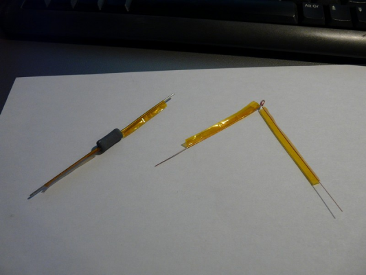
I'm a bit stuck at the endstop soldering; I don't know which wire goes to which pole.
- S (yellow) should go to C
- gnd (black) NC or NO ?
- +5 (red) NC or NO ?
Could somebody help me on this one ?
I'm also a bit lost on some of the lcd panel wire :
black should be on vss (with brown & some sort of rotating switch), rw and k (with the second rotating switch)
a red wire is on this 2nd switch, should I solder back & this red on rw ?
orange is on rs, but one of the 1st switch's leg is already soldered there; should I unsolder it and put it back on with orange ?
Edited 1 time(s). Last edit at 02/01/2013 03:47PM by Nico3ck.
|
Re: Nico's Build February 01, 2013 04:43PM |
Registered: 13 years ago Posts: 2,947 |
Nico3ck Wrote:
-------------------------------------------------------
> Hi all, I've started my tantillus build, taking
> pictures as I progress, I'll put them here later
> when I'm finished.
> It's looking good so far, I'm still waiting some
> parts before putting everything's together.
>
>
> I'm a bit stuck at the endstop soldering; I don't
> know which wire goes to which pole.
>
> - S (yellow) should go to C
> - gnd (black) NC or NO ?
> - +5 (red) NC or NO ?
Black and white go to the outer terminals of the switch (no polarity). The middle terminal and red wire are not used.
>
>
> Could somebody help me on this one ?
>
>
>
> I'm also a bit lost on some of the lcd panel wire
> :
>
> black should be on vss (with brown & some sort of
> rotating switch), rw and k (with the second
> rotating switch)
> a red wire is on this 2nd switch, should I solder
> back & this red on rw ?
>
> orange is on rs, but one of the 1st switch's leg
> is already soldered there; should I unsolder it
> and put it back on with orange ?
This is how it should look. I will try and get a better diagram up soon.
Note the colors may differ due to batch differences.
Let me know if you need more help.
| FFF Settings Calculator | Gcode post processors | Geometric Object Deposition Tool Blog |
| Tantillus.org | Mini Printable Lathe | How NOT to install a Pololu driver |
|
Re: Nico's Build February 01, 2013 05:36PM |
Registered: 11 years ago Posts: 41 |
|
Re: Nico's Build February 01, 2013 06:11PM |
Registered: 13 years ago Posts: 2,947 |
Nico3ck Wrote:
-------------------------------------------------------
> My left rotating switch does not seems to be
> soldered as yours.
>
> What I see on your .jpg, from the left, is :
>
> 1 - brown
> 2 - long red + left back leg + wire to leg of second potentiometer
> 3 - center leg
> 4 - orange+ short red just the orange
> 5 - right back leg + short jumper from 1 (brown) + jumper to 16 (brown)
>
> Is that right ? the rest seems ok.
Very close just 2 - 4 were a little off
-------------------------------------------------------
> My left rotating switch does not seems to be
> soldered as yours.
>
> What I see on your .jpg, from the left, is :
>
> 1 - brown
> 2 - long red + left back leg + wire to leg of second potentiometer
> 3 - center leg
> 4 - orange
> 5 - right back leg + short jumper from 1 (brown) + jumper to 16 (brown)
>
> Is that right ? the rest seems ok.
Very close just 2 - 4 were a little off
| FFF Settings Calculator | Gcode post processors | Geometric Object Deposition Tool Blog |
| Tantillus.org | Mini Printable Lathe | How NOT to install a Pololu driver |
|
Re: Nico's Build February 01, 2013 07:39PM |
Registered: 11 years ago Posts: 41 |
|
Re: Nico's Build March 05, 2013 11:09AM |
Registered: 11 years ago Posts: 41 |
Yesterday I finally finished building / preping my Tantillus; x, y & z are moving, extruder is extruding.
But (as everything can't be perfect) my lcd screen doesn't light up.
Is there something wrong with the way i've plugged it in ? if no I'll add some picture of the solered wires tonight.
edit
wiring :
The goo-like stuff is silicon; I put some because I feared the wires would touch, but now it seemed a bad idea ...
Edited 1 time(s). Last edit at 03/05/2013 07:16PM by Nico3ck.
|
Re: Nico's Build March 05, 2013 11:07PM |
Registered: 11 years ago Posts: 78 |
|
Re: Nico's Build March 06, 2013 03:05PM |
Registered: 11 years ago Posts: 41 |
|
Re: Nico's Build March 06, 2013 04:52PM |
Registered: 13 years ago Posts: 2,947 |
Ok I think I found the problem. Have a look at the attached picture with my notes
. I think you have an extra wire going to RW. Also the red and brown on the connector will need to be switched after correcting the above noted wire.
| FFF Settings Calculator | Gcode post processors | Geometric Object Deposition Tool Blog |
| Tantillus.org | Mini Printable Lathe | How NOT to install a Pololu driver |
|
Re: Nico's Build March 07, 2013 05:56PM |
Registered: 11 years ago Posts: 41 |
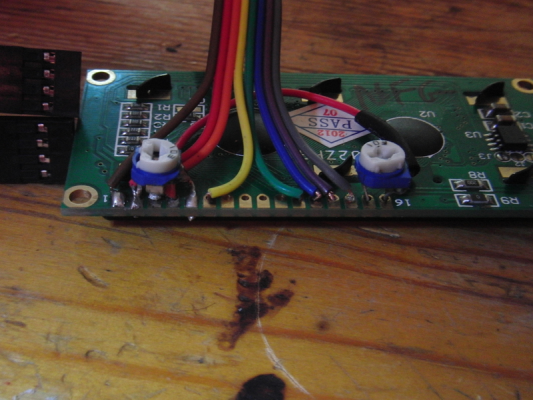
After some soldering, it's still the same.
Here is a picture of what it looks like:
From right to left :
1 - brown + black (goes to 5)
2 - red + red (goes to 2nd pot right leg) + 1st pot right leg
3 - 1st pot front leg
4 - orange
5- 1st pot left leg + black (goes to 1)
6 - yellow
7 -
8 -
9 -
10 -
11- green
12 - blue
13 - purple
14 - gray
15 - 2nd pot front leg
16 - 2nd pot left leg
|
Re: Nico's Build March 07, 2013 07:00PM |
Registered: 13 years ago Posts: 2,947 |
Nico3ck Wrote:
-------------------------------------------------------
> After some soldering, it's still the same.
>
> Here is a picture of what it looks like:
> [img4.hostingpics.net]
> 0103.jpg
>
>
> From right to left :
>
> 1 - brown + black (goes to 5)
> 2 - red + red (goes to 2nd pot right leg) + 1st
> pot right leg
> 3 - 1st pot front leg
> 4 - orange
> 5- 1st pot left leg + black (goes to 1)
> 6 - yellow
> 7 -
> 8 -
> 9 -
> 10 -
> 11- green
> 12 - blue
> 13 - purple
> 14 - gray
> 15 - 2nd pot front leg
> 16 - 2nd pot left leg
That picture still shows a red wire going to pin 5 but your description does not have the red wire and I believe it is the issue.
| FFF Settings Calculator | Gcode post processors | Geometric Object Deposition Tool Blog |
| Tantillus.org | Mini Printable Lathe | How NOT to install a Pololu driver |
|
Re: Nico's Build March 08, 2013 03:52PM |
Registered: 11 years ago Posts: 41 |
I uploaded twice the same image ... This is why sleep is nedeed from time to time !
|
Re: Nico's Build March 08, 2013 03:59PM |
Registered: 13 years ago Posts: 2,947 |
I probably should have asked you this first. Have you tried turning the pots? Start with the one on the left first and see if you can get the back light lit. Once it is lit up then turn the other one to set the contrast so you can read the display. Also some of the displays came with a little solder jumper soldered that needs to be unsoldered, its marked j3. If it was none of those can you check with a meter you are getting 5v and ground.
Edited 1 time(s). Last edit at 03/08/2013 04:13PM by Sublime.
Edited 1 time(s). Last edit at 03/08/2013 04:13PM by Sublime.
| FFF Settings Calculator | Gcode post processors | Geometric Object Deposition Tool Blog |
| Tantillus.org | Mini Printable Lathe | How NOT to install a Pololu driver |
|
Re: Nico's Build March 08, 2013 04:23PM |
Registered: 11 years ago Posts: 41 |
|
Re: Nico's Build March 08, 2013 04:34PM |
Registered: 13 years ago Posts: 2,947 |
Ok that tells us you have a short between + and - . Is it possible one of the legs on the pots is bent so far it is touching the center tap of the pot? Can you test for continuity between solder points.
| FFF Settings Calculator | Gcode post processors | Geometric Object Deposition Tool Blog |
| Tantillus.org | Mini Printable Lathe | How NOT to install a Pololu driver |
|
Re: Nico's Build March 08, 2013 04:59PM |
Registered: 11 years ago Posts: 41 |
|
Re: Nico's Build March 08, 2013 05:39PM |
Registered: 13 years ago Posts: 2,947 |
Hmmm.. If those are readings from the meter set on resistance than the 1 <> 2 looks like the one with continuity which could be because it is still connected to the RAMPS board.
Can you unplug all the wires from the four pin connector that has the red/brown wires and try putting them in in this order Red, Brown, Orange, Yellow and try connecting it to the RAMPS and see if you get 5v and ground at the LCD. If you still do not get 5V we can rule out a short caused by the other wires. In the end it could be a bad LCD ( I have one that does not work out of 100 [the one I use for pictures]).
Can you unplug all the wires from the four pin connector that has the red/brown wires and try putting them in in this order Red, Brown, Orange, Yellow and try connecting it to the RAMPS and see if you get 5v and ground at the LCD. If you still do not get 5V we can rule out a short caused by the other wires. In the end it could be a bad LCD ( I have one that does not work out of 100 [the one I use for pictures]).
| FFF Settings Calculator | Gcode post processors | Geometric Object Deposition Tool Blog |
| Tantillus.org | Mini Printable Lathe | How NOT to install a Pololu driver |
|
Re: Nico's Build March 11, 2013 07:12PM |
Registered: 11 years ago Posts: 41 |
After scratching my head for a while, I re-checked every wires, and when I was re-reading the post I found that the first picture was not showing rightly the red & brown wire.
Just after the bend, they twist and the brown is plugged in what seems the red and vice-versa - theses wires don't need to be reversed.
So since the 7th we are trying to work on a something that can't work that way, the joys of tele-debugging ...
So after getting brown and red rigth, I do have something - the backlight seems to be working a bit, around 1/10th of [farm9.staticflickr.com] (even with max power from the pot).
There are some black pixel on the lcd, seemingly placed at random.
|
Re: Nico's Build March 11, 2013 09:29PM |
Registered: 13 years ago Posts: 2,947 |
I do not know if they have any protection against reverse voltage so it may be damaged in some way. Or it may be that jumper J3 has a little solder on it still. Try running a utility knife between the pads while the power is off to be sure the circuit is broken. It enables a smart brightness feature that does not work correctly for some reason.
| FFF Settings Calculator | Gcode post processors | Geometric Object Deposition Tool Blog |
| Tantillus.org | Mini Printable Lathe | How NOT to install a Pololu driver |
|
Re: Nico's Build March 12, 2013 07:08PM |
Registered: 11 years ago Posts: 41 |
Well, no change after cleaning a bit more the 2 pads ... It seems my lcd is cooked.
Do you have some lcd left ?
If yes, I'd like to order another - if you could solder it and test it on your printer I'll gladdly pay for the extra.
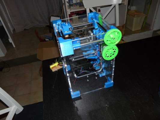
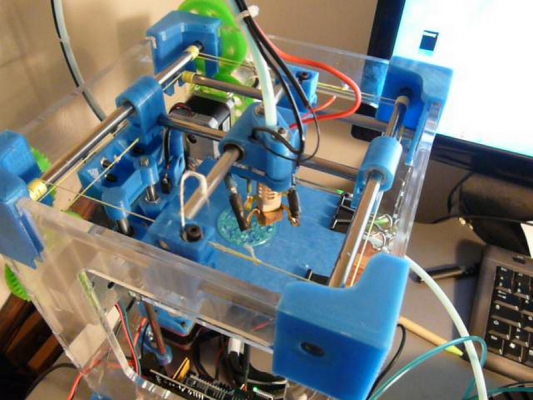
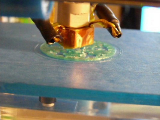
For some good news, my Tantillus is up and running, some fine tuning is still going on (axis step by unit atm, there are still some small ridge forming due to an over-extrusion of pla).
Here are some videos of a gear bearing printing :
- begining : [www.youtube.com]
- hotend close-up : [www.youtube.com]
- longer HD middle print : [www.youtube.com]
Do you hear / see something that's wrong ?
Sadly It could not print to the end, pronterface froze at ~70%.
I'm now printing a support for my fans, edited to take them correctly.
I'll post some picture of the ongoing build later and my thoughts about it.
|
Re: Nico's Build March 12, 2013 07:30PM |
Registered: 13 years ago Posts: 2,947 |
Yes just email me about the LCD.
If the video is actually how the machine sounds I think there is something wrong but I have no idea. Or the microphone was cutting in and out because of the volume of the machine. The sounds between when the sound cut in and out sounded fine. A little high pitch which could just be the motor current being a little off. Other than that it looks perfectly assembled. Looks like you spent some time to get the cables perfect.
If the video is actually how the machine sounds I think there is something wrong but I have no idea. Or the microphone was cutting in and out because of the volume of the machine. The sounds between when the sound cut in and out sounded fine. A little high pitch which could just be the motor current being a little off. Other than that it looks perfectly assembled. Looks like you spent some time to get the cables perfect.
| FFF Settings Calculator | Gcode post processors | Geometric Object Deposition Tool Blog |
| Tantillus.org | Mini Printable Lathe | How NOT to install a Pololu driver |
|
Re: Nico's Build March 12, 2013 08:43PM |
Registered: 11 years ago Posts: 41 |
The motors tends to "sing" when printing something round, this can be this noice you are talking about. As my X and Y slipped twice during calibration, I upped a little the current going to the motors.
While printing my fan mount, I noticed the gears are rattling a bit when going rapidly from side to side, in certain positions.
After my cables got loose (I over tightned them and they slepped on the axis) I tried to get them really right.
I found it easier to wrap them in a neat coil around the shaft from the start.
My main concern is now to perfectly tune the pla flow, to keep of the ridges & little blobs (next test : 348)
|
Re: Nico's Build March 26, 2013 12:41PM |
Registered: 11 years ago Posts: 41 |
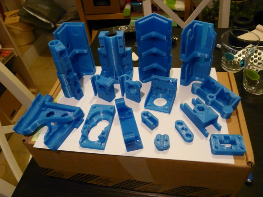
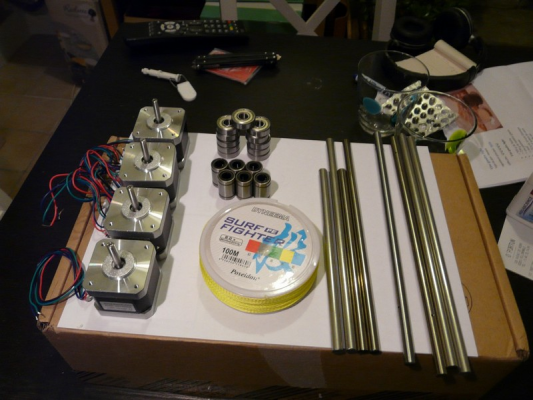
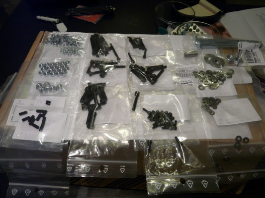
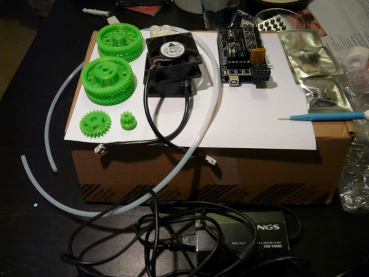
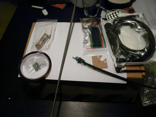
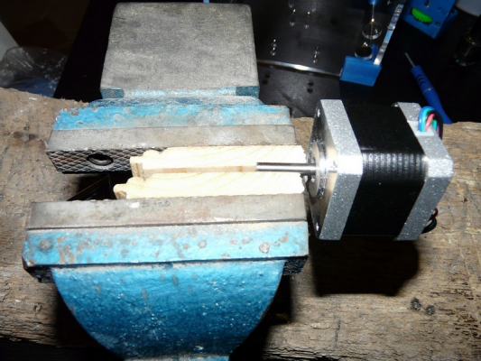
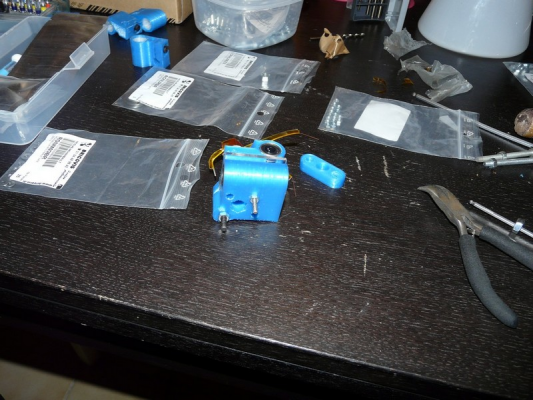
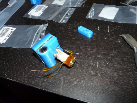
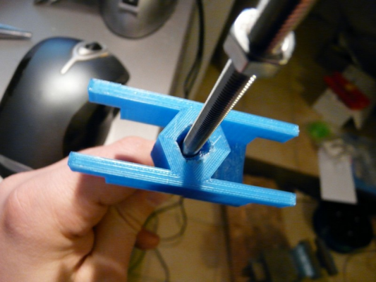
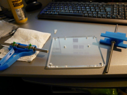
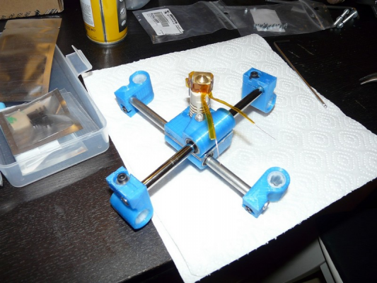
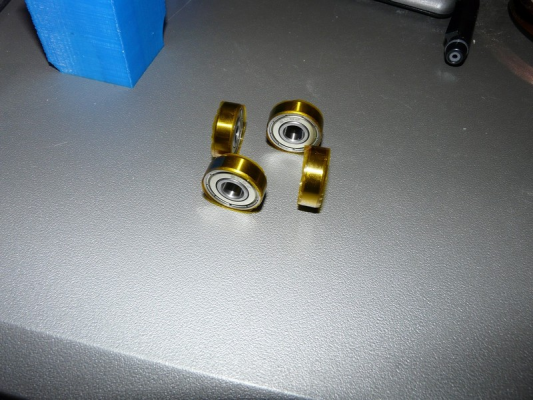
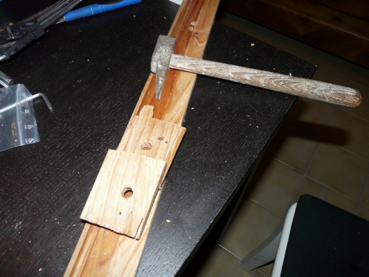
Here are a few picture taken during the build, and my comments
"Strucure" pieces, printed by by Ghun from the french forum
Cables, motors, bearings
Screws
Fans (I did not used theses ones but a larger one), gears, electronics
Encoder, lcd screen and cable kit
Starting j-head build
j-head done, ready to take fly
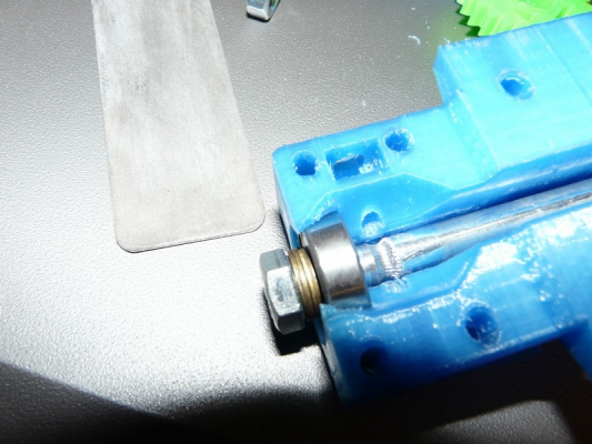
Work started on the hobbed bolt
Montage de la partie fixe de l'exrudeur
Ajusting ...
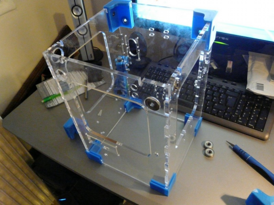
Structure nearly done
Creating a flat
Finishing the extruder's bolted part
Finishing the extruder's moving part
Working on Z
Working working working
A little csk to get clean drilled holes
Searching the perfect fit (did not work in the end
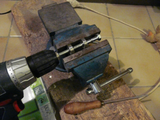
Since 2 of my rods were a bit bit large, I needed to use unusual tools for a 3D printer
Starts to looks good !
Working zone
First real print
After a few starting problems - the thread count on Z was off by minus 20% - everything is nicely tuned. I just printed the encoder knob on 0.1, quality is nice (at max speed)
|
Re: Nico's Build March 26, 2013 01:47PM |
Registered: 13 years ago Posts: 2,947 |
Nice work documenting your build. I had the hardest time remembering to take pictures and I built a lot more than one.
Please keep us updated with results.
Please keep us updated with results.
| FFF Settings Calculator | Gcode post processors | Geometric Object Deposition Tool Blog |
| Tantillus.org | Mini Printable Lathe | How NOT to install a Pololu driver |
|
Re: Nico's Build March 27, 2013 02:43AM |
Registered: 11 years ago Posts: 111 |
|
Re: Nico's Build March 27, 2013 06:37AM |
Registered: 11 years ago Posts: 41 |
Sorry, only registered users may post in this forum.
