Variant of Goopyplastic's Tantillus Variant (Ingentis)
Posted by jimjimma
|
Variant of Goopyplastic's Tantillus Variant (Ingentis) July 01, 2013 12:32AM |
Registered: 12 years ago Posts: 95 |
Hi Folks
I've been working on a variant to Goopyplastic's excellent T-Slot Tantillus and I'd like to get some feedback before I start building it in earnest. I’m uncertain if this should be a new post or not as it leans heavily on Goopy’s work so I'll stick it here to start with and I'm sure I'll get told if it should go somewhere else.
The attached images show the WIP model. I'll post more if there's interest and/or as it progresses.
The principal change I've made is significant increase in size, the current design is ~450mm per side (external dimensions).
The increase in size has driven or facilitated a number of other changes:
• Thicker linear rods to support the print head/carriage; twice the span would increase the deflection for a given lateral force so this should be offset with thicker rails. In my case I’m using 12mm rods for the x-y rails supporting the print head and leaving the side rails as 8mm, mainly because this is what I have to hand and I don’t want to have to change the bearing mounts on the corner brackets to accommodate for a larger roller bearing.
• Moving the Nema’s driving the x-y motion back into the printer’s envelope; I’ve used a similar approach to Ultimaker in placing the Nema below the relevant drive/linear rail and linking the 2 with GT2 pullies and an appropriate closed loop belt (all off the shelf stuff from SDP-SI).
• Completely re-designed Z axis; including an 8mm Lead screw instead of spectra, using T-slot and 90 degree brackets to support the platform and using horizontal t-slot supports for the top and bottom mounts. This should facilitate easy Z scaling and allows for a variety of nut traps to be used to link the lead screw nut to the platform.
Further changes I’ve made:
• Using Sintered Bronze bushings instead of linear bearings – mainly because I’ve got spares and that’s what Ultimaker use. This has meant I’ve had to re-do the original x/y ends to take the bushings as well as accommodating for clamping the 12mm rods.
• Re-designed print head/carriage for Dual Bowden extruders. This is still very much a WIP but the idea is to have each hot end clamped in place with 2 pieces of machined aluminium (top and bottom sides of the printed mounting structure). This should allow for micro adjustment of the HE heights relative to each other with some sort of consistent thickness shim material. The top piece of Aluminium will also be tapped with an M5 thread to take a push fit pneumatic coupler. This is not properly represented on the attached renders btw.
Anyway, although I’ve heavily modified my mendelmax and I’m no stranger to 3D Design, I’d greatly appreciate any feedback, positive or negative. Also happy to share source files if anyone want’s to tinker with the design.
Edited 1 time(s). Last edit at 02/18/2014 10:00PM by MattMoses.
|
Re: Variant of Goopyplastic's Tantillus Variant July 01, 2013 08:39AM |
Registered: 10 years ago Posts: 180 |
I have oilite bearings on my tantillus, they work great. No noise, smooth, cheap and self lubricating.
I'd probably start with the 8mm rods for the crossbar. The larger diameter rod would add extra mass and the 8mm rods are pretty stiff at 400mm length. If anything I would make the side rods thicker to lower the number of cable loops required. To allow for the extra cable, you'll probably have to modify the corners (rod position) anyway.
I'd probably start with the 8mm rods for the crossbar. The larger diameter rod would add extra mass and the 8mm rods are pretty stiff at 400mm length. If anything I would make the side rods thicker to lower the number of cable loops required. To allow for the extra cable, you'll probably have to modify the corners (rod position) anyway.
|
Re: Variant of Goopyplastic's Tantillus Variant July 01, 2013 02:36PM |
Registered: 13 years ago Posts: 2,947 |
jimjimma Wrote:
-------------------------------------------------------
> • Thicker linear rods to support the print
> head/carriage; twice the span would increase the
> deflection for a given lateral force so this
> should be offset with thicker rails. In my case
> I’m using 12mm rods for the x-y rails supporting
> the print head and leaving the side rails as 8mm,
> mainly because this is what I have to hand and I
> don’t want to have to change the bearing mounts
> on the corner brackets to accommodate for a larger
> roller bearing.
As Lajos mentioned the extra moving mass is a bad thing. I personally think it could defeat the design of the light weight head which allows the high acceleration speeds which results in the sharp print definition. Also as Lajos says the larger diameter on the outer rods would help with the cable drive on a machine that large.
One more thing I notice is the changes you made to the X/Y ends to accommodate the larger rods look to have moved the cable hole vertically which would then change the alignment with the outer rods where it is spooled. Right now the cables run perfectly level and only has any angular deflection as a result of the spooling on and off of the rods. This would also be an issue with using larger outer rods. To use larger rods I would simply scale the entire model up by 20% for 10mm rods or 40% for 12mm. That way spacing and alignment stay the same. Then you could resize the bearing hole by a fraction to fit the appropriate bearings. Then resize the machine to your specs.
> • Moving the Nema’s driving the x-y motion
> back into the printer’s envelope; I’ve used a
> similar approach to Ultimaker in placing the Nema
> below the relevant drive/linear rail and linking
> the 2 with GT2 pullies and an appropriate closed
> loop belt (all off the shelf stuff from SDP-SI).
Just remember the belts are where backlash is introduced if the pulleys are not designed perfectly and if the belts are not tight enough. Also be sure to have the largest possible diameter you can so the possible backlash in the teeth is averaged over more teeth.
I have one machine running belts between the motors and the shafts. It is quieter then the geared machines by a little but I can see slight differences in the prints between the machines that I assume are a result of the belts.
I really like Goopyplastics direct drive method. Also Lajos's laser/milled gears seem nice and should run quieter than the printed ones.
Also if it is the noise people do not like they can always print a cover for the gears and pack it full of grease. They would last way longer and be almost silent.
> • Completely re-designed Z axis; including an
> 8mm Lead screw instead of spectra, using T-slot
> and 90 degree brackets to support the platform and
> using horizontal t-slot supports for the top and
> bottom mounts. This should facilitate easy Z
> scaling and allows for a variety of nut traps to
> be used to link the lead screw nut to the
> platform.
I would stay away from the 8mm lead screw and the upper bearing support on the lead screw. Both introduce more Z wobble. The reason for the 6mm lead screw is it is weaker then the smooth rods so if it wobbles the smooth rods should not wobble. But with the 8mm lead screw if it wobbles it will force the smooth rods around and you get wobble.
The bearing at the top means if it wobbles a little instead of the top of the rod just moving around it now wobbles in the middle where the Z stage is attached.
>
> Further changes I’ve made:
> • Using Sintered Bronze bushings instead of
> linear bearings – mainly because I’ve got
> spares and that’s what Ultimaker use. This has
> meant I’ve had to re-do the original x/y ends to
> take the bushings as well as accommodating for
> clamping the 12mm rods.
Bronze works really well just remember you are using 5/16" rods on the outside not 8mm since high precision rods do not fit in 608 bearings
> • Re-designed print head/carriage for Dual
> Bowden extruders. This is still very much a WIP
> but the idea is to have each hot end clamped in
> place with 2 pieces of machined aluminium (top and
> bottom sides of the printed mounting structure).
> This should allow for micro adjustment of the HE
> heights relative to each other with some sort of
> consistent thickness shim material. The top piece
> of Aluminium will also be tapped with an M5 thread
> to take a push fit pneumatic coupler. This is not
> properly represented on the attached renders btw.
Nice looking carriage. Be sure to have the spacing between the rods correct vertically so they do not bind.
I would put both hotends on the same side of one of the rods so they are as close as possible to each other since the further apart the smaller the combined build area.
I would put the hotends next to each other on X axis not the Y and reduce the Y axis by as much as you were will to lose from having the hotends in the current configuration. This is because the cantilever will always be weaker the further out you go, but sideways along X you can simply widen the arms apart if needed.
Edited 1 time(s). Last edit at 07/01/2013 04:49PM by Sublime.
| FFF Settings Calculator | Gcode post processors | Geometric Object Deposition Tool Blog |
| Tantillus.org | Mini Printable Lathe | How NOT to install a Pololu driver |
|
Re: Variant of Goopyplastic's Tantillus Variant July 01, 2013 06:49PM |
Registered: 12 years ago Posts: 95 |
Hi Lajos and Sublime
Thank you both for your feedback. Appreciate both of you taking the time; although I've not posted in this forum before I've been lurking for quite a while so I'm aware of your respective efforts with Tantillus development (and it's inception in Sublime's case).
I was in 2 minds about the rail diameters as I'm keen to use what I've already got but as you both suggest, extra weight on the moving parts is sub optimal. I'll see what I can find in the way of 10mm rods and appropriate bearings for the support/drive rails and go back to 8mm rods to support the carriage. Now i think about it, deflection should be pretty low anyway (compared to a mendel style bot) given that the carriage is supported by 6 rods and (if my static mechanics isn't too rusty ) any load and associated deflection is distributed across the system.
I've assumed twice as many cable turns around the 8mm shafts, there looks like there is enough room but I will double check.
In response to Sublime's comments:
> One more thing I notice is the changes you made to the
> X/Y ends to accommodate the larger rods look to have
> moved the cable hole vertically which would then change
> the alignment with the outer rods where it is spooled
This must be a trick of perspective as the holes are perfectly in line with the outer edge of the rods - obviously this will have to change if the support rod diameters increase. I've not included the spectra in the renders so far, will add it once I've settled on the mechanical design.
> Just remember the belts are where backlash is introduced if the
> pulleys are not designed perfectly and if the belts are not tight
> enough. Also be sure to have the largest possible diameter you can
> so the possible backlash in the teeth is averaged over more teeth.
Duly noted, I've been toying with drive gears instead (I'd likely buy proper machined ones if I went that way) but I've heard good things about FHT timing belts that apparently have even less backlash than GT2. I've got a plan for getting the belts good and tight, we'll have to see how that pans out.
At worse case, it should be easy enough to change the design to use drive gears if backlash artifacts are apparent.
> I would stay away from the 8mm lead screw and the upper bearing
> support on the lead screw. Both introduce more Z wobble. The
> reason for the 6mm lead screw is it is weaker then the smooth
> rods so if it wobbles the smooth rods should not wobble. But with
> the 8mm lead screw if it wobbles it will force the smooth rods
> around and you get wobble.
> The bearing at the top means if it wobbles a little instead of the top
> of the rod just moving around it now wobbles in the middle where
> the Z stage is attached.
Another thing I've been procrastinating about - I don't like having a loose end to the lead screw - apart from oscillating like crazy during small infills, it looks untidy . In saying that, I hear you. Perhaps some sort of flexible bushing (ruber tube or similar) at the top end would work to minimize vibrations without constraining things too much. The thing about z wobble is that it stems from bad engineering (IMO), a well machined, straight lead screw and coupler, combined with a correctly orientated motor and nut should not produce any wobble. Not sure how to handle this - I have some 1/4 inch acme screws I could cannibalize from my MM, so perhaps I'll keep them up my sleeve if this design produces wobble.
> Bronze works really well just remember you are using 5/16" rods
> on the outside not 8mm since high precision rods do not fit in 608
> bearings
Bloody good point, I had completely missed that - If I go for 10mm support rails, this turns into a voyage of discovery as I'd need to find bearings that support the rails snugly, 6900-ZZ looks like a candidate as it's 22mm external (same as 608-ZZ). No doubt the precision 10mm rods won't fit in those either though. Did you look into reducing the ends of the rods to make them fit? I assume the reduction required is <0.5 mm. As I don't intend to place gears on the outside of the frame, the reduction would only need to be on the last 10mm (ish) of the rod.
> I would put the hotends next to each other on X axis not the Y and
> reduce the Y axis by as much as you were will to lose from having the
> hotends in the current configuration. This is because the cantilever will
> always be weaker the further out you go, but sideways along X you can > simply widen the arms apart if needed.
You've read my mind - I was half way through shifting the extruders to one side of the rails when I closed the laptop last night. Previous design was a result of my love for symmetry to the detriment of good practice and maximized build area.
I'll post some more images once I've made the suggested changes.
Many thanks again for you feedback!
Thank you both for your feedback. Appreciate both of you taking the time; although I've not posted in this forum before I've been lurking for quite a while so I'm aware of your respective efforts with Tantillus development (and it's inception in Sublime's case).
I was in 2 minds about the rail diameters as I'm keen to use what I've already got but as you both suggest, extra weight on the moving parts is sub optimal. I'll see what I can find in the way of 10mm rods and appropriate bearings for the support/drive rails and go back to 8mm rods to support the carriage. Now i think about it, deflection should be pretty low anyway (compared to a mendel style bot) given that the carriage is supported by 6 rods and (if my static mechanics isn't too rusty ) any load and associated deflection is distributed across the system.
I've assumed twice as many cable turns around the 8mm shafts, there looks like there is enough room but I will double check.
In response to Sublime's comments:
> One more thing I notice is the changes you made to the
> X/Y ends to accommodate the larger rods look to have
> moved the cable hole vertically which would then change
> the alignment with the outer rods where it is spooled
This must be a trick of perspective as the holes are perfectly in line with the outer edge of the rods - obviously this will have to change if the support rod diameters increase. I've not included the spectra in the renders so far, will add it once I've settled on the mechanical design.
> Just remember the belts are where backlash is introduced if the
> pulleys are not designed perfectly and if the belts are not tight
> enough. Also be sure to have the largest possible diameter you can
> so the possible backlash in the teeth is averaged over more teeth.
Duly noted, I've been toying with drive gears instead (I'd likely buy proper machined ones if I went that way) but I've heard good things about FHT timing belts that apparently have even less backlash than GT2. I've got a plan for getting the belts good and tight, we'll have to see how that pans out.
At worse case, it should be easy enough to change the design to use drive gears if backlash artifacts are apparent.
> I would stay away from the 8mm lead screw and the upper bearing
> support on the lead screw. Both introduce more Z wobble. The
> reason for the 6mm lead screw is it is weaker then the smooth
> rods so if it wobbles the smooth rods should not wobble. But with
> the 8mm lead screw if it wobbles it will force the smooth rods
> around and you get wobble.
> The bearing at the top means if it wobbles a little instead of the top
> of the rod just moving around it now wobbles in the middle where
> the Z stage is attached.
Another thing I've been procrastinating about - I don't like having a loose end to the lead screw - apart from oscillating like crazy during small infills, it looks untidy
. In saying that, I hear you. Perhaps some sort of flexible bushing (ruber tube or similar) at the top end would work to minimize vibrations without constraining things too much. The thing about z wobble is that it stems from bad engineering (IMO), a well machined, straight lead screw and coupler, combined with a correctly orientated motor and nut should not produce any wobble. Not sure how to handle this - I have some 1/4 inch acme screws I could cannibalize from my MM, so perhaps I'll keep them up my sleeve if this design produces wobble.> Bronze works really well just remember you are using 5/16" rods
> on the outside not 8mm since high precision rods do not fit in 608
> bearings
Bloody good point, I had completely missed that - If I go for 10mm support rails, this turns into a voyage of discovery as I'd need to find bearings that support the rails snugly, 6900-ZZ looks like a candidate as it's 22mm external (same as 608-ZZ). No doubt the precision 10mm rods won't fit in those either though. Did you look into reducing the ends of the rods to make them fit? I assume the reduction required is <0.5 mm. As I don't intend to place gears on the outside of the frame, the reduction would only need to be on the last 10mm (ish) of the rod.
> I would put the hotends next to each other on X axis not the Y and
> reduce the Y axis by as much as you were will to lose from having the
> hotends in the current configuration. This is because the cantilever will
> always be weaker the further out you go, but sideways along X you can > simply widen the arms apart if needed.
You've read my mind - I was half way through shifting the extruders to one side of the rails when I closed the laptop last night. Previous design was a result of my love for symmetry to the detriment of good practice and maximized build area.
I'll post some more images once I've made the suggested changes.
Many thanks again for you feedback!
|
Re: Variant of Goopyplastic's Tantillus Variant July 01, 2013 07:08PM |
Registered: 13 years ago Posts: 2,947 |
jimjimma Wrote:
-------------------------------------------------------
> In response to Sublime's comments:
>
> > One more thing I notice is the changes you made
> to the
> > X/Y ends to accommodate the larger rods look to
> have
> > moved the cable hole vertically which would then
> change
> > the alignment with the outer rods where it is
> spooled
>
> This must be a trick of perspective as the holes
> are perfectly in line with the outer edge of the
> rods - obviously this will have to change if the
> support rod diameters increase. I've not included
> the spectra in the renders so far, will add it
> once I've settled on the mechanical design.
I just knew I had the cables basically sitting on top of the rods as the cable went through the X/Y end and assumed with the larger rods that point had to go up. But looking now I assume you got around this by not having bushings in the center where the rods cross allowing you to have them closer together then the original with the linear bearings.
>
> > Just remember the belts are where backlash is
> introduced if the
> > pulleys are not designed perfectly and if the
> belts are not tight
> > enough. Also be sure to have the largest
> possible diameter you can
> > so the possible backlash in the teeth is
> averaged over more teeth.
>
> Duly noted, I've been toying with drive gears
> instead (I'd likely buy proper machined ones if I
> went that way) but I've heard good things about
> FHT timing belts that apparently have even less
> backlash than GT2. I've got a plan for getting the
> belts good and tight, we'll have to see how that
> pans out.
> At worse case, it should be easy enough to change
> the design to use drive gears if backlash
> artifacts are apparent.
>
> > I would stay away from the 8mm lead screw and
> the upper bearing
> > support on the lead screw. Both introduce more Z
> wobble. The
> > reason for the 6mm lead screw is it is weaker
> then the smooth
> > rods so if it wobbles the smooth rods should not
> wobble. But with
> > the 8mm lead screw if it wobbles it will force
> the smooth rods
> > around and you get wobble.
> > The bearing at the top means if it wobbles a
> little instead of the top
> > of the rod just moving around it now wobbles in
> the middle where
> > the Z stage is attached.
>
> Another thing I've been procrastinating about - I
> don't like having a loose end to the lead screw -
> apart from oscillating like crazy during small
> infills, it looks untidy. In saying that, I
> hear you. Perhaps some sort of flexible bushing
> (ruber tube or similar) at the top end would work
> to minimize vibrations without constraining things
> too much. The thing about z wobble is that it
> stems from bad engineering (IMO), a well machined,
> straight lead screw and coupler, combined with a
> correctly orientated motor and nut should not
> produce any wobble. Not sure how to handle this -
> I have some 1/4 inch acme screws I could
> cannibalize from my MM, so perhaps I'll keep them
> up my sleeve if this design produces wobble.
>
If it is a true lead screw then odds are you will be fine, but be careful with using cheap threaded rod. Also note on the original design I have the top of the rod end inside of a plastic part so you can not see the end wobble as well as it prevent things from getting caught on it.
But I have to say a belt or cable driven Z axis it much nicer. It is really fast and has no wobble. Printers like the UP which has always made good prints uses a belt driven Z. Printxel also uses one and produces really nice prints.
> > Bronze works really well just remember you are
> using 5/16" rods
> > on the outside not 8mm since high precision rods
> do not fit in 608
> > bearings
>
> Bloody good point, I had completely missed that -
> If I go for 10mm support rails, this turns into a
> voyage of discovery as I'd need to find bearings
> that support the rails snugly, 6900-ZZ looks like
> a candidate as it's 22mm external (same as
> 608-ZZ). No doubt the precision 10mm rods won't
> fit in those either though. Did you look into
> reducing the ends of the rods to make them fit? I
> assume the reduction required is <0.5 mm. As I
> don't intend to place gears on the outside of the
> frame, the reduction would only need to be on the
> last 10mm (ish) of the rod.
Yes you can machine them or in your case with the pulleys on the inside you could just press fit them on the shafts. The 5/16" rods I use measure 7.92mm so 80micron less then 8mm, any more I think could be a problem.
>
> > I would put the hotends next to each other on X
> axis not the Y and
> > reduce the Y axis by as much as you were will to
> lose from having the
> > hotends in the current configuration. This is
> because the cantilever will
> > always be weaker the further out you go, but
> sideways along X you can > simply widen the arms
> apart if needed.
>
> You've read my mind - I was half way through
> shifting the extruders to one side of the rails
> when I closed the laptop last night. Previous
> design was a result of my love for symmetry to
> the detriment of good practice and maximized build
> area.
Yeah I am an artist and have that same issue. But with Tantillus I had to break the rules and the entire Z axis and carriage are offset to the left.
>
> I'll post some more images once I've made the
> suggested changes.
Please do.
-------------------------------------------------------
> In response to Sublime's comments:
>
> > One more thing I notice is the changes you made
> to the
> > X/Y ends to accommodate the larger rods look to
> have
> > moved the cable hole vertically which would then
> change
> > the alignment with the outer rods where it is
> spooled
>
> This must be a trick of perspective as the holes
> are perfectly in line with the outer edge of the
> rods - obviously this will have to change if the
> support rod diameters increase. I've not included
> the spectra in the renders so far, will add it
> once I've settled on the mechanical design.
I just knew I had the cables basically sitting on top of the rods as the cable went through the X/Y end and assumed with the larger rods that point had to go up. But looking now I assume you got around this by not having bushings in the center where the rods cross allowing you to have them closer together then the original with the linear bearings.
>
> > Just remember the belts are where backlash is
> introduced if the
> > pulleys are not designed perfectly and if the
> belts are not tight
> > enough. Also be sure to have the largest
> possible diameter you can
> > so the possible backlash in the teeth is
> averaged over more teeth.
>
> Duly noted, I've been toying with drive gears
> instead (I'd likely buy proper machined ones if I
> went that way) but I've heard good things about
> FHT timing belts that apparently have even less
> backlash than GT2. I've got a plan for getting the
> belts good and tight, we'll have to see how that
> pans out.
> At worse case, it should be easy enough to change
> the design to use drive gears if backlash
> artifacts are apparent.
>
> > I would stay away from the 8mm lead screw and
> the upper bearing
> > support on the lead screw. Both introduce more Z
> wobble. The
> > reason for the 6mm lead screw is it is weaker
> then the smooth
> > rods so if it wobbles the smooth rods should not
> wobble. But with
> > the 8mm lead screw if it wobbles it will force
> the smooth rods
> > around and you get wobble.
> > The bearing at the top means if it wobbles a
> little instead of the top
> > of the rod just moving around it now wobbles in
> the middle where
> > the Z stage is attached.
>
> Another thing I've been procrastinating about - I
> don't like having a loose end to the lead screw -
> apart from oscillating like crazy during small
> infills, it looks untidy
. In saying that, I> hear you. Perhaps some sort of flexible bushing
> (ruber tube or similar) at the top end would work
> to minimize vibrations without constraining things
> too much. The thing about z wobble is that it
> stems from bad engineering (IMO), a well machined,
> straight lead screw and coupler, combined with a
> correctly orientated motor and nut should not
> produce any wobble. Not sure how to handle this -
> I have some 1/4 inch acme screws I could
> cannibalize from my MM, so perhaps I'll keep them
> up my sleeve if this design produces wobble.
>
If it is a true lead screw then odds are you will be fine, but be careful with using cheap threaded rod. Also note on the original design I have the top of the rod end inside of a plastic part so you can not see the end wobble as well as it prevent things from getting caught on it.
But I have to say a belt or cable driven Z axis it much nicer. It is really fast and has no wobble. Printers like the UP which has always made good prints uses a belt driven Z. Printxel also uses one and produces really nice prints.
> > Bronze works really well just remember you are
> using 5/16" rods
> > on the outside not 8mm since high precision rods
> do not fit in 608
> > bearings
>
> Bloody good point, I had completely missed that -
> If I go for 10mm support rails, this turns into a
> voyage of discovery as I'd need to find bearings
> that support the rails snugly, 6900-ZZ looks like
> a candidate as it's 22mm external (same as
> 608-ZZ). No doubt the precision 10mm rods won't
> fit in those either though. Did you look into
> reducing the ends of the rods to make them fit? I
> assume the reduction required is <0.5 mm. As I
> don't intend to place gears on the outside of the
> frame, the reduction would only need to be on the
> last 10mm (ish) of the rod.
Yes you can machine them or in your case with the pulleys on the inside you could just press fit them on the shafts. The 5/16" rods I use measure 7.92mm so 80micron less then 8mm, any more I think could be a problem.
>
> > I would put the hotends next to each other on X
> axis not the Y and
> > reduce the Y axis by as much as you were will to
> lose from having the
> > hotends in the current configuration. This is
> because the cantilever will
> > always be weaker the further out you go, but
> sideways along X you can > simply widen the arms
> apart if needed.
>
> You've read my mind - I was half way through
> shifting the extruders to one side of the rails
> when I closed the laptop last night. Previous
> design was a result of my love for symmetry to
> the detriment of good practice and maximized build
> area.
Yeah I am an artist and have that same issue. But with Tantillus I had to break the rules and the entire Z axis and carriage are offset to the left.
>
> I'll post some more images once I've made the
> suggested changes.
Please do.
| FFF Settings Calculator | Gcode post processors | Geometric Object Deposition Tool Blog |
| Tantillus.org | Mini Printable Lathe | How NOT to install a Pololu driver |
|
Re: Variant of Goopyplastic's Tantillus Variant July 02, 2013 07:27PM |
Registered: 12 years ago Posts: 95 |
Sublime Wrote:
-------------------------------------------------------
> If it is a true lead screw then odds are you will be fine,
> but be careful with using cheap threaded rod.
> Also note on the original design I have the top
> of the rod end inside of a plastic part so you can not
> see the end wobble as well as it prevent things from
> getting caught on it.
Yes, I am using a 'proper' lead screw and It should be easy enough for me to adjust the top Z mount to mimic your approach of covering the end of the lead screw. Incidentally, I'm not expecting this all to just work, iterative development and adjustment is what I expect.
> But I have to say a belt or cable driven Z axis it much
> nicer. It is really fast and has no wobble. Printers like
> the UP which has always made good prints uses a belt
> driven Z. Printxel also uses one and produces really nice prints.
I did look at the belt/cable options but one of the reasons I wanted to build a x/y gantry style bot was that I'd have more freedom to engineer the bed without worrying as much about weight implications. Given the current design, I suspect the bed weight (gravity included) would cause the nema to struggle with a belt/cable approach. Less so with a lead screw, even if it's not as quick. I wonder now if this is flawed reasoning.... I used an UP! to print the parts for my MM, so I'm familiar with it's quality although I have to say it's best feature was the snap away supports, I've yet to see any of the open source slicers do as good a job.
> Yes you can machine them or in your case with the pulleys
> on the inside you could just press fit them on the shafts.
> The 5/16" rods I use measure 7.92mm so 80micron less then
> 8mm, any more I think could be a problem.
I
'll just buy the rods and bearings and see how it goes, press fit might not be the best option as I may well need to pull it apart if some of these new ideas don't pan out :|.
I've altered the design to use 10mm outer rods and 8mm x/y rods, still fiddling with the carriage. Render of the new version attached, still a bit clunky but the HE's are as close together as they can be now and as close to the support rods as possible.
Edited 1 time(s). Last edit at 07/03/2013 06:24AM by jimjimma.
|
Re: Variant of Goopyplastic's Tantillus Variant July 06, 2013 06:21AM |
Registered: 10 years ago Posts: 22 |
For the longer X/Y rods I've been considering what SDP-SI calls a pipe shaft, which they offer in 8mm with a 3mm bore, the tubular rod should be a little stiffer for the longer span and lighter weight to reduce the mass of the system. Only problem is they are quite expensive at $35.65 each for 300mm length, which is the bummer. If anyone knows of a cheaper source for such a rail please let me know. [sdp-si.com]
Edited 1 time(s). Last edit at 07/06/2013 07:06AM by cns1.
Edited 1 time(s). Last edit at 07/06/2013 07:06AM by cns1.
|
Re: Variant of Goopyplastic's Tantillus Variant July 08, 2013 05:57AM |
Registered: 12 years ago Posts: 95 |
A bit of an update.
So, with an upgrade to 10mm outer rods, I now find that I can't find GT2 pulleys with a 10mm bore diameter(that don't cost $25 each). So, cognizant of Sublime's advice above, I'm going to go for Herringbone gears like the original Tantillus; I had a look at off the shelf ones, fell off my chair at how expensive they are and decided that that particular wheel didn't need re-inventing. I'll look into a wee printed box I can fill with Lithium grease (or whatever is appropriate) to cover the gears and reduce noise.
I've also been fiddling with Extruder carriage design, as I'm using press fit bushings instead of LMU88s, I've been able to get it pretty small while maintaining the precious precious symmetry. I'll try a test print once I've got my new E3D Hot end dialled in.
Sublime, if you get a moment, can you confirm that my maths is correct for cable turns:
On the original Tantillus, with a build area 100mm^2, the cable is wrapped around the (nearly) 8mm rod 5 times in each direction. That gives ~25mm per wrap and 125mm movement in each direction from centre. Given that the relevant x/y end is equidistant between the rods when the cable is installed and thus only needs to move 50-60mm I assume the extra 2-3 turns on each side is to maintain enough friction to prevent the cable slipping. So,with a 300mm^2 build area using 10mm rods, (giving ~31mm per turn), i need 5 turns to move the head 150mm from centre. So, burning question: how many extra turns? I was thinking just 1 extra each side of the hole to allow for some over run. Any sagely advice?
Few More pics below.


|
Re: Variant of Goopyplastic's Tantillus Variant July 08, 2013 11:54AM |
Registered: 13 years ago Posts: 2,947 |
jimjimma Wrote:
-----------------------------------------------
> I've also been fiddling with Extruder carriage
> design, as I'm using press fit bushings instead of
> LMU88s, I've been able to get it pretty small
> while maintaining the precious precious symmetry.
> I'll try a test print once I've got my new E3D Hot
> end dialled in.
Looks good. Does that keep the hotends as close as possible while staying symmetrical? What is the foot print of the carriage like that?
>
> Sublime, if you get a moment, can you confirm that
> my maths is correct for cable turns:
> On the original Tantillus, with a build area
> 100mm^2, the cable is wrapped around the (nearly)
> 8mm rod 5 times in each direction. That gives
> ~25mm per wrap and 125mm movement in each
> direction from centre. Given that the relevant x/y
> end is equidistant between the rods when the cable
> is installed and thus only needs to move 50-60mm I
> assume the extra 2-3 turns on each side is to
> maintain enough friction to prevent the cable
> slipping. So,with a 300mm^2 build area using 10mm
> rods, (giving ~31mm per turn), i need 5 turns to
> move the head 150mm from centre. So, burning
> question: how many extra turns? I was thinking
> just 1 extra each side of the hole to allow for
> some over run. Any sagely advice?
The extra turns have a few uses:
1) Extra friction (as you mentioned)
2) Safety so when you install them and do not get the carriage attached at the center wrap it still works.
3) Most importantly is you need the offset that the 10 wraps creates so the cable clears the X/Y end.
For a larger machine I would be sure to have at least 1 wrap per side of the hole more than the amount you calculated you will need for reason 2 above.
| FFF Settings Calculator | Gcode post processors | Geometric Object Deposition Tool Blog |
| Tantillus.org | Mini Printable Lathe | How NOT to install a Pololu driver |
|
Re: Variant of Goopyplastic's Tantillus Variant July 08, 2013 12:56PM |
Registered: 10 years ago Posts: 180 |
What a great idea pushing the two hotends closer using the gap between the bearings.
I've been thinking about a carriage with two hotends also, using a mounting plate at the bottom for easier access to the hotend. But I was planning to keep the carriage itself two pieces so the holes for the X and Y bearing could be printed on the Z axis, similar to how the original carriage is oriented for printing. (As in you would print a cylinder by laying down circles instead of printing a cylinder laying on its side.) Although it might just be overthinking it
Do you need active cooling for the e3d hotend? I'm staying with hotends.com j-heads for now, hoping the frame mounted fans will provide enough cooling.
|
Re: Variant of Goopyplastic's Tantillus Variant July 08, 2013 03:37PM |
Registered: 13 years ago Posts: 2,947 |
lajos Wrote:
-------------------------------------------------------
(As in you
> would print a cylinder by laying down circles
> instead of printing a cylinder laying on its
> side.) Although it might just be overthinking it
>
Without support those never turn out well. Printing it vertically like the original is so much easier and produces a stronger part in most cases. For an even stronger part print it on a diagonal like this [technocraticanarchist.blogspot.ca]
| FFF Settings Calculator | Gcode post processors | Geometric Object Deposition Tool Blog |
| Tantillus.org | Mini Printable Lathe | How NOT to install a Pololu driver |
|
Re: Variant of Goopyplastic's Tantillus Variant July 08, 2013 07:35PM |
Registered: 12 years ago Posts: 95 |
Thanks for further feedback guys.
Sublime Wrote:
-------------------------------------------------------
> Without support those never turn out well.
> Printing it vertically like the original is so
> much easier and produces a stronger part in most
> cases. For an even stronger part print it on a
> diagonal like this
> [technocraticanarchist.blogspot.ca]
> olid-prints.html
Agree, I have a cunning plan in this regard, I'll post some picks once I've realized it.
In the case of the parts that take a press fit bushing, as Lajos suggests, it makes sense to print them on their side as the concentric circles of the internal perimeter will be most regular if printed on the x/y plane, ensuring the best possible alignment of the bushing.
> Looks good. Does that keep the hotends as close as
> possible while staying symmetrical? What is the foot
> print of the carriage like that?
First Image below shows the footprint against your original ( I wasn't sure if the curved piece on top left of your design constrained the carriage's travel) - I think I can trim another 5mm off the footprint on mine by reducing the aluminum plate size. As I'm using E3D hotends they are as close together as possible, Jheads could get closer but I think the press fit Bowden connectors would fowl against the rod that passes between them. Distance between the nozzles is 26mm btw.
I'm aware it looks a bit flimsy from the side, solving this in the next iteration.


|
Re: Variant of Goopyplastic's Tantillus Variant July 09, 2013 12:44PM |
Registered: 13 years ago Posts: 2,947 |
jimjimma Wrote:
-------------------------------------------------------
> First Image below shows the footprint against your
> original ( I wasn't sure if the curved piece on
> top left of your design constrained the carriage's
> travel)
No the X/Y ends fit in the space next to the curved part. It seemed like the only way to get a 100mm movement inside a printed case that was only 200mm on the outside. Now with all the variants and even the laser cut case the space available is much greater.
| FFF Settings Calculator | Gcode post processors | Geometric Object Deposition Tool Blog |
| Tantillus.org | Mini Printable Lathe | How NOT to install a Pololu driver |
|
Re: Variant of Goopyplastic's Tantillus Variant July 11, 2013 02:13AM |
Registered: 10 years ago Posts: 22 |
|
Re: Variant of Goopyplastic's Tantillus Variant July 11, 2013 02:39AM |
Registered: 12 years ago Posts: 95 |
|
Re: Variant of Goopyplastic's Tantillus Variant July 12, 2013 12:14AM |
Registered: 12 years ago Posts: 45 |
|
Re: Variant of Goopyplastic's Tantillus Variant July 25, 2013 10:56PM |
Registered: 12 years ago Posts: 95 |
Hi All
Thought I'd post an update as it's been a few weeks.
Design is effectively complete. Pictures below. The outer dimensions of the frame is 465mm on all axis. The build plate's usable areas is about 300mm per side for a dual extruder config. I've designed for a lead screw Z but I'm getting more and more interested in a belt driven version. May change that in the next week or so – Any thoughts? Would the Z platform drop if the current to the motor is cut?
Other than that, I’ve added 2 x Rich Horne’s Greg’s Wade Reloaded for Bowden at the back of the bot and made few changes to the carriage.
With respect to build, I’ve got the aluminium extrusions. Rods, bearings etc are in the post. Should be starting to put it together in the next few weeks.
So, the big question is.... what do I call it? Best suggestion I've had so far is 'Gigantillus' Other options: B.F.T. or Tantillus Rex. Any thoughts? Sublime, you're the progenitor of this, so if you have a preference, please let me know. I suck at names, so any help appreciated.
Thought I'd post an update as it's been a few weeks.
Design is effectively complete. Pictures below. The outer dimensions of the frame is 465mm on all axis. The build plate's usable areas is about 300mm per side for a dual extruder config. I've designed for a lead screw Z but I'm getting more and more interested in a belt driven version. May change that in the next week or so – Any thoughts? Would the Z platform drop if the current to the motor is cut?
Other than that, I’ve added 2 x Rich Horne’s Greg’s Wade Reloaded for Bowden at the back of the bot and made few changes to the carriage.
With respect to build, I’ve got the aluminium extrusions. Rods, bearings etc are in the post. Should be starting to put it together in the next few weeks.
So, the big question is.... what do I call it? Best suggestion I've had so far is 'Gigantillus'
Other options: B.F.T. or Tantillus Rex. Any thoughts? Sublime, you're the progenitor of this, so if you have a preference, please let me know. I suck at names, so any help appreciated. 


|
Re: Variant of Goopyplastic's Tantillus Variant July 25, 2013 11:40PM |
Registered: 13 years ago Posts: 2,947 |
jimjimma Wrote:
-------------------------------------------------------
I've
> designed for a lead screw Z but I'm getting more
> and more interested in a belt driven version. May
> change that in the next week or so – Any
> thoughts? Would the Z platform drop if the current
> to the motor is cut?
Yes it drops when power is cut.
I would make it two belts connected with a rod going sideways across the bottom and then gear down the entire thing so you keep a higher resolution.
>
> Other than that, I’ve added 2 x Rich Horne’s
> Greg’s Wade Reloaded for Bowden at the back of
> the bot and made few changes to the carriage.
Do note that Tantillus uses 2.7:1 gearing and gregs is some where between 4 and 5:1 so you may not get as fast of retracts.
> So, the big question is.... what do I call it?
> Best suggestion I've had so far is 'Gigantillus'
> Other options: B.F.T. or Tantillus Rex. Any
> thoughts? Sublime, you're the progenitor of this,
> so if you have a preference, please let me know. I
> suck at names, so any help appreciated.
I found the name Tantillus by looking for words that meant small in Latin. Doing the same for large I found:
tantus : so large, so great, of such a size.
Edited 1 time(s). Last edit at 07/26/2013 10:37PM by Sublime.
-------------------------------------------------------
I've
> designed for a lead screw Z but I'm getting more
> and more interested in a belt driven version. May
> change that in the next week or so – Any
> thoughts? Would the Z platform drop if the current
> to the motor is cut?
Yes it drops when power is cut.
I would make it two belts connected with a rod going sideways across the bottom and then gear down the entire thing so you keep a higher resolution.
>
> Other than that, I’ve added 2 x Rich Horne’s
> Greg’s Wade Reloaded for Bowden at the back of
> the bot and made few changes to the carriage.
Do note that Tantillus uses 2.7:1 gearing and gregs is some where between 4 and 5:1 so you may not get as fast of retracts.
> So, the big question is.... what do I call it?
> Best suggestion I've had so far is 'Gigantillus'
>
Other options: B.F.T. or Tantillus Rex. Any> thoughts? Sublime, you're the progenitor of this,
> so if you have a preference, please let me know. I
> suck at names, so any help appreciated.
I found the name Tantillus by looking for words that meant small in Latin. Doing the same for large I found:
tantus : so large, so great, of such a size.
Edited 1 time(s). Last edit at 07/26/2013 10:37PM by Sublime.
| FFF Settings Calculator | Gcode post processors | Geometric Object Deposition Tool Blog |
| Tantillus.org | Mini Printable Lathe | How NOT to install a Pololu driver |
|
Re: Variant of Goopyplastic's Tantillus Variant July 26, 2013 07:26PM |
Registered: 10 years ago Posts: 180 |
It's looking really nice! I've started working on a bigger tantillus in openscad, and it's a lot of work to even get simple parts made. Let alone create an assembly. I mainly started the project to learn openscad, but I've had second thoughts many times, a package like solidworks/inventor would've been a magnitude more productive.
It looks like you'll be using the e3d hotends?
Is this the final placement for the extruders? Do you think you'll have a good path for the filament through the bowden cable?
It looks like you'll be using the e3d hotends?
Is this the final placement for the extruders? Do you think you'll have a good path for the filament through the bowden cable?
|
Re: Variant of Goopyplastic's Tantillus Variant July 28, 2013 11:31PM |
Registered: 12 years ago Posts: 95 |
Sublime Wrote:
-------------------------------------------------------
> Yes it drops when power is cut.
>
> I would make it two belts connected with a rod
> going sideways across the bottom and then gear
> down the entire thing so you keep a higher
> resolution.
That makes good sense, I've got a bunch of spare GT2 pulleys and belts so I can avoid buying another lead screw too. I'll do some work on it this week and put a design up for your perusal if you don't mind? Not sure about how to gear it though. I assume you want it geared so that you've got an acceptably small movement per full step but what's the magic number?
When I do the math: I have 32 tooth pulleys with a pitch diameter of 20.4mm. this gives a pitch circumference of 64.088mm so one full step = 0.32044 mm. So if I gear at a ratio that takes a single step down to 0.1mm would that work do you think?
On a quasi related note, seen this Threadless Ballscrew? Were I not already juggling too many balls I'd be giving this a go instead of a lead screw.
> Do note that Tantillus uses 2.7:1 gearing and
> gregs is some where between 4 and 5:1 so you may
> not get as fast of retracts.
Hmmm, so, you may have noted that this is a dual extruder set-up and in fact I'm seriously considering 3 extruders in order to achieve the perimeter/infill/support holy trinity. With that in mind, I've started thinking that I might actually want to gear each extruder differently: Perimeters should be accurate but still support fast retracts. Infill should be as fast as possible. Supports should be somewhere in between I guess.
I was suprised that the Tantillus ratio was actually lower than the Gregs as I'd assumed you'd want a very accurate extrusion length. Clearly, this can't be an issue given the quality of the prints you're achieving.
So, now I'm in a quandary, why are Gregs geared the way they are if you can achieve what you do with nearly half the ratio?
> I found the name Tantillus by looking for words
> that meant small in Latin. Doing the same for
> large I found:
>
> tantus : so large, so great, of such a size.
I like Tantus, a good nod in the direction of Tantillus. Tantus it is. Thanks! Rest assured, I will be giving you appropriate props when I stick the files on Github.
Oh, also, look what I did over the weekend
Edited 1 time(s). Last edit at 07/29/2013 01:45AM by jimjimma.
-------------------------------------------------------
> Yes it drops when power is cut.
>
> I would make it two belts connected with a rod
> going sideways across the bottom and then gear
> down the entire thing so you keep a higher
> resolution.
That makes good sense, I've got a bunch of spare GT2 pulleys and belts so I can avoid buying another lead screw too. I'll do some work on it this week and put a design up for your perusal if you don't mind? Not sure about how to gear it though. I assume you want it geared so that you've got an acceptably small movement per full step but what's the magic number?
When I do the math: I have 32 tooth pulleys with a pitch diameter of 20.4mm. this gives a pitch circumference of 64.088mm so one full step = 0.32044 mm. So if I gear at a ratio that takes a single step down to 0.1mm would that work do you think?
On a quasi related note, seen this Threadless Ballscrew? Were I not already juggling too many balls I'd be giving this a go instead of a lead screw.
> Do note that Tantillus uses 2.7:1 gearing and
> gregs is some where between 4 and 5:1 so you may
> not get as fast of retracts.
Hmmm, so, you may have noted that this is a dual extruder set-up and in fact I'm seriously considering 3 extruders in order to achieve the perimeter/infill/support holy trinity. With that in mind, I've started thinking that I might actually want to gear each extruder differently: Perimeters should be accurate but still support fast retracts. Infill should be as fast as possible. Supports should be somewhere in between I guess.
I was suprised that the Tantillus ratio was actually lower than the Gregs as I'd assumed you'd want a very accurate extrusion length. Clearly, this can't be an issue given the quality of the prints you're achieving.
So, now I'm in a quandary, why are Gregs geared the way they are if you can achieve what you do with nearly half the ratio?
> I found the name Tantillus by looking for words
> that meant small in Latin. Doing the same for
> large I found:
>
> tantus : so large, so great, of such a size.
I like Tantus, a good nod in the direction of Tantillus. Tantus it is. Thanks! Rest assured, I will be giving you appropriate props when I stick the files on Github
.Oh, also, look what I did over the weekend

Edited 1 time(s). Last edit at 07/29/2013 01:45AM by jimjimma.
|
Re: Variant of Goopyplastic's Tantillus Variant July 29, 2013 12:04AM |
Registered: 12 years ago Posts: 95 |
lajos Wrote:
-------------------------------------------------------
> It's looking really nice! I've started working on
> a bigger tantillus in openscad, and it's a lot of
> work to even get simple parts made. Let alone
> create an assembly. I mainly started the project
> to learn openscad, but I've had second thoughts
> many times, a package like solidworks/inventor
> would've been a magnitude more productive.
>
Thanks
I'm using Rhino for this one as I'm time constrained and I don't ened anything to be parametric. I really like inventor but I don't have the 5-6 years experience I have with Rhino so things are slower going. Designing anything complex in openSCAD sounds like pulling teath, I know it's free and all but I have less time than I do less money
> It looks like you'll be using the e3d hotends?
Yup - I might even make it a tripple extruder version, still procrastinating. Sanjay from E3D has even offered to sponsor the Tantus, not sure what that means yet but he gave me some free nozzles after I killed mine (due to my own stupidity). The E3D hotend is waaay better than my old hotends.com j-head. I thoroughly reccomend them.
> Is this the final placement for the extruders? Do
> you think you'll have a good path for the filament
> through the bowden cable?
I think so, they are axially allinged with the press fit connectors at the top of the unit so I assume the filament will have a good path.
|
Re: Variant of Goopyplastic's Tantillus Variant July 29, 2013 01:03PM |
Registered: 13 years ago Posts: 2,947 |
jimjimma Wrote:
-------------------------------------------------------
> That makes good sense, I've got a bunch of spare
> GT2 pulleys and belts so I can avoid buying
> another lead screw too. I'll do some work on it
> this week and put a design up for your perusal if
> you don't mind? Not sure about how to gear it
> though. I assume you want it geared so that you've
> got an acceptably small movement per full step but
> what's the magic number?
> When I do the math: I have 32 tooth pulleys with a
> pitch diameter of 20.4mm. this gives a pitch
> circumference of 64.088mm so one full step =
> 0.32044 mm. So if I gear at a ratio that takes a
> single step down to 0.1mm would that work do you
> think?
Yeah 0.1 would be ok. Personally I would have it move at 0.005 per micro step (@ 16x) or 0.08 per whole step. This will give you a nice default of 0.16 if you care about the whole steps (which I do not) and will allow all kinds of good low layer heights below 0.1 using the micro stepping without the worry of rounding errors.
> > Do note that Tantillus uses 2.7:1 gearing and
> > gregs is some where between 4 and 5:1 so you
> may
> > not get as fast of retracts.
>
> Hmmm, so, you may have noted that this is a dual
> extruder set-up and in fact I'm seriously
> considering 3 extruders in order to achieve the
> perimeter/infill/support holy trinity. With that
> in mind, I've started thinking that I might
> actually want to gear each extruder differently:
> Perimeters should be accurate but still support
> fast retracts. Infill should be as fast as
> possible. Supports should be somewhere in between
> I guess.
> I was suprised that the Tantillus ratio was
> actually lower than the Gregs as I'd assumed you'd
> want a very accurate extrusion length. Clearly,
> this can't be an issue given the quality of the
> prints you're achieving.
> So, now I'm in a quandary, why are Gregs geared
> the way they are if you can achieve what you do
> with nearly half the ratio?
The original gears for the extruder were 3.3:1 and worked well but had really small teeth that made printing harder and life a little shorter. They would reach a retraction speed of 40mm/s where as the current ones with the same hobbed bolt will reach 47mm/s.
The issue with resolution of the extruder really will only come into play with small nozzle diameters and low layers combined.
For a 0.5mm nozzle and 2.7:1 gears you can go down to (optimal minimum) 0.08 without worry of losing precision of deposition. Then down to (absolute minimum) 0.041mm you will have good control and precision but the overall resolution will go down because the extrusion width needs to be increased below the optimal minimum layer height.
>
> > I found the name Tantillus by looking for words
> > that meant small in Latin. Doing the same for
> > large I found:
> >
> > tantus : so large, so great, of such a size.
>
> I like Tantus, a good nod in the direction of
> Tantillus. Tantus it is. Thanks! Rest assured, I
> will be giving you appropriate props when I stick
> the files on Github.
Thanks that really is what I get the most enjoyment out of.
>
> Oh, also, look what I did over the weekend
Looks good.
-------------------------------------------------------
> That makes good sense, I've got a bunch of spare
> GT2 pulleys and belts so I can avoid buying
> another lead screw too. I'll do some work on it
> this week and put a design up for your perusal if
> you don't mind? Not sure about how to gear it
> though. I assume you want it geared so that you've
> got an acceptably small movement per full step but
> what's the magic number?
> When I do the math: I have 32 tooth pulleys with a
> pitch diameter of 20.4mm. this gives a pitch
> circumference of 64.088mm so one full step =
> 0.32044 mm. So if I gear at a ratio that takes a
> single step down to 0.1mm would that work do you
> think?
Yeah 0.1 would be ok. Personally I would have it move at 0.005 per micro step (@ 16x) or 0.08 per whole step. This will give you a nice default of 0.16 if you care about the whole steps (which I do not) and will allow all kinds of good low layer heights below 0.1 using the micro stepping without the worry of rounding errors.
> > Do note that Tantillus uses 2.7:1 gearing and
> > gregs is some where between 4 and 5:1 so you
> may
> > not get as fast of retracts.
>
> Hmmm, so, you may have noted that this is a dual
> extruder set-up and in fact I'm seriously
> considering 3 extruders in order to achieve the
> perimeter/infill/support holy trinity. With that
> in mind, I've started thinking that I might
> actually want to gear each extruder differently:
> Perimeters should be accurate but still support
> fast retracts. Infill should be as fast as
> possible. Supports should be somewhere in between
> I guess.
> I was suprised that the Tantillus ratio was
> actually lower than the Gregs as I'd assumed you'd
> want a very accurate extrusion length. Clearly,
> this can't be an issue given the quality of the
> prints you're achieving.
> So, now I'm in a quandary, why are Gregs geared
> the way they are if you can achieve what you do
> with nearly half the ratio?
The original gears for the extruder were 3.3:1 and worked well but had really small teeth that made printing harder and life a little shorter. They would reach a retraction speed of 40mm/s where as the current ones with the same hobbed bolt will reach 47mm/s.
The issue with resolution of the extruder really will only come into play with small nozzle diameters and low layers combined.
For a 0.5mm nozzle and 2.7:1 gears you can go down to (optimal minimum) 0.08 without worry of losing precision of deposition. Then down to (absolute minimum) 0.041mm you will have good control and precision but the overall resolution will go down because the extrusion width needs to be increased below the optimal minimum layer height.
>
> > I found the name Tantillus by looking for words
> > that meant small in Latin. Doing the same for
> > large I found:
> >
> > tantus : so large, so great, of such a size.
>
> I like Tantus, a good nod in the direction of
> Tantillus. Tantus it is. Thanks! Rest assured, I
> will be giving you appropriate props when I stick
> the files on Github
.Thanks that really is what I get the most enjoyment out of.
>
> Oh, also, look what I did over the weekend
Looks good.
| FFF Settings Calculator | Gcode post processors | Geometric Object Deposition Tool Blog |
| Tantillus.org | Mini Printable Lathe | How NOT to install a Pololu driver |
|
Re: Variant of Goopyplastic's Tantillus Variant July 29, 2013 02:31PM |
Registered: 10 years ago Posts: 180 |
> The E3D hotend is waaay better than my old hotends.com j-head.
That's a pretty high bar I've never had any issues with my j-head nor my home made ptfe bar/aluminum nozzle hotend (that was used on my cnc machine).
I've been following the discussion on the metal hotends in the general forum and it sounds like the e3d hotend is far ahead of its rivals. There are still a number of complaints about jams, so I'm curious to hear your experience with the dual head setup.
Keep up the good work!
That's a pretty high bar
I've never had any issues with my j-head nor my home made ptfe bar/aluminum nozzle hotend (that was used on my cnc machine).I've been following the discussion on the metal hotends in the general forum and it sounds like the e3d hotend is far ahead of its rivals. There are still a number of complaints about jams, so I'm curious to hear your experience with the dual head setup.
Keep up the good work!
|
Re: Variant of Goopyplastic's Tantillus Variant July 30, 2013 10:25PM |
Registered: 12 years ago Posts: 95 |
Sublime Wrote:
-------------------------------------------------------
>
> Yeah 0.1 would be ok. Personally I would have it
> move at 0.005 per micro step (@ 16x) or 0.08 per
> whole step. This will give you a nice default of
> 0.16 if you care about the whole steps (which I do
> not) and will allow all kinds of good low layer
> heights below 0.1 using the micro stepping without
> the worry of rounding errors.
Ok, so with a 64.088 pitch diameter on the pulleys, 1 need to gear at 1:4 to give 16mm mm/rev or 0.08 whole step.
>
> The original gears for the extruder were 3.3:1 and
> worked well but had really small teeth that made
> printing harder and life a little shorter. They
> would reach a retraction speed of 40mm/s where as
> the current ones with the same hobbed bolt will
> reach 47mm/s.
>
> The issue with resolution of the extruder really
> will only come into play with small nozzle
> diameters and low layers combined.
>
> For a 0.5mm nozzle and 2.7:1 gears you can go down
> to (optimal minimum) 0.08 without worry of losing
> precision of deposition. Then down to (absolute
> minimum) 0.041mm you will have good control and
> precision but the overall resolution will go down
> because the extrusion width needs to be increased
> below the optimal minimum layer height.
It'll be easy enough for me to create a smaller Herringbone from the trifidhunter script. I'll do that to get closer to the 2.7:1 value.
Can you explain where you derive the optimum minumum values from? I assume is some factor of viscosity nozzle diameter and flow rate? I've been toying with your calcualtor and I'll use the values it suggests but I'm interested in how you've come up with the numbers as it's the first time I've come across the concept. The perim nozzle I intend to use is 0.25. I assume the same gear ration will be acceptable for a smaller nozzle...
Thankyou again for your continued help with this.
-------------------------------------------------------
>
> Yeah 0.1 would be ok. Personally I would have it
> move at 0.005 per micro step (@ 16x) or 0.08 per
> whole step. This will give you a nice default of
> 0.16 if you care about the whole steps (which I do
> not) and will allow all kinds of good low layer
> heights below 0.1 using the micro stepping without
> the worry of rounding errors.
Ok, so with a 64.088 pitch diameter on the pulleys, 1 need to gear at 1:4 to give 16mm mm/rev or 0.08 whole step.
>
> The original gears for the extruder were 3.3:1 and
> worked well but had really small teeth that made
> printing harder and life a little shorter. They
> would reach a retraction speed of 40mm/s where as
> the current ones with the same hobbed bolt will
> reach 47mm/s.
>
> The issue with resolution of the extruder really
> will only come into play with small nozzle
> diameters and low layers combined.
>
> For a 0.5mm nozzle and 2.7:1 gears you can go down
> to (optimal minimum) 0.08 without worry of losing
> precision of deposition. Then down to (absolute
> minimum) 0.041mm you will have good control and
> precision but the overall resolution will go down
> because the extrusion width needs to be increased
> below the optimal minimum layer height.
It'll be easy enough for me to create a smaller Herringbone from the trifidhunter script. I'll do that to get closer to the 2.7:1 value.
Can you explain where you derive the optimum minumum values from? I assume is some factor of viscosity nozzle diameter and flow rate? I've been toying with your calcualtor and I'll use the values it suggests but I'm interested in how you've come up with the numbers as it's the first time I've come across the concept. The perim nozzle I intend to use is 0.25. I assume the same gear ration will be acceptable for a smaller nozzle...
Thankyou again for your continued help with this
.
|
Re: Variant of Goopyplastic's Tantillus Variant July 31, 2013 12:15PM |
Registered: 13 years ago Posts: 2,947 |
jimjimma Wrote:
-------------------------------------------------------
> It'll be easy enough for me to create a smaller
> Herringbone from the trifidhunter script. I'll do
> that to get closer to the 2.7:1 value.
I would aim for 3:1 for a good all around extruder.
> Can you explain where you derive the optimum
> minumum values from? I assume is some factor of
> viscosity nozzle diameter and flow rate? I've been
> toying with your calcualtor and I'll use the
> values it suggests but I'm interested in how
> you've come up with the numbers as it's the first
> time I've come across the concept. The perim
> nozzle I intend to use is 0.25. I assume the same
> gear ration will be acceptable for a smaller
> nozzle...
The absolute minimum is simply printing at the nozzle diameter and the layer height is 0.16666 of the nozzle diameter. Or in other words the extrusion width is 600% of the height.
The maximum layer height is printing at the free air extrusion width at a height equal to 0.66 of the free air extrusion width (nozzle diameter + die swell). Or in other words the width is 150% of the height.
All the extrusion widths between the Max height = max width and min height = min width are a result of a linear division between them. This seems to result in the same back pressure inside the hotend resulting in the same extrusion properties through out the height range.
The width at the optimal maximum layer height is 200% of the height.
The optimal minimum layer height takes into account the E steps per mm. It calculates the layer height based on the volume of one step being equal to a dot the size of the extrusion width at that height. Or in other words it makes sure it can extrude a line segment the same width as length to ensure good control over the deposition and to be able to produce small diameter posts like the railings on the Eiffel tower model.
So for a smaller nozzle I would make the gearing higher. Maybe for the 0.25 I would start by trying the original Triffid gears and possibly go up from there. When I was trying to go really low layer with a small hotend I built a 10.89:1 extruder (3.3:1 x 3.3:1) but never used it as clogs of small extruder are a real pain.
>
> Thankyou again for your continued help with this
>.
No problem just keep us informed and up to date.
Edited 1 time(s). Last edit at 07/31/2013 01:27PM by Sublime.
-------------------------------------------------------
> It'll be easy enough for me to create a smaller
> Herringbone from the trifidhunter script. I'll do
> that to get closer to the 2.7:1 value.
I would aim for 3:1 for a good all around extruder.
> Can you explain where you derive the optimum
> minumum values from? I assume is some factor of
> viscosity nozzle diameter and flow rate? I've been
> toying with your calcualtor and I'll use the
> values it suggests but I'm interested in how
> you've come up with the numbers as it's the first
> time I've come across the concept. The perim
> nozzle I intend to use is 0.25. I assume the same
> gear ration will be acceptable for a smaller
> nozzle...
The absolute minimum is simply printing at the nozzle diameter and the layer height is 0.16666 of the nozzle diameter. Or in other words the extrusion width is 600% of the height.
The maximum layer height is printing at the free air extrusion width at a height equal to 0.66 of the free air extrusion width (nozzle diameter + die swell). Or in other words the width is 150% of the height.
All the extrusion widths between the Max height = max width and min height = min width are a result of a linear division between them. This seems to result in the same back pressure inside the hotend resulting in the same extrusion properties through out the height range.
The width at the optimal maximum layer height is 200% of the height.
The optimal minimum layer height takes into account the E steps per mm. It calculates the layer height based on the volume of one step being equal to a dot the size of the extrusion width at that height. Or in other words it makes sure it can extrude a line segment the same width as length to ensure good control over the deposition and to be able to produce small diameter posts like the railings on the Eiffel tower model.
So for a smaller nozzle I would make the gearing higher. Maybe for the 0.25 I would start by trying the original Triffid gears and possibly go up from there. When I was trying to go really low layer with a small hotend I built a 10.89:1 extruder (3.3:1 x 3.3:1) but never used it as clogs of small extruder are a real pain.
>
> Thankyou again for your continued help with this
>
.No problem just keep us informed and up to date.
Edited 1 time(s). Last edit at 07/31/2013 01:27PM by Sublime.
| FFF Settings Calculator | Gcode post processors | Geometric Object Deposition Tool Blog |
| Tantillus.org | Mini Printable Lathe | How NOT to install a Pololu driver |
|
Re: Variant of Goopyplastic's Tantillus Variant August 05, 2013 05:46AM |
Registered: 12 years ago Posts: 95 |
Any tips on drilling hardened steel rods?? Even with Cobalt drill bits and drill press set to reasonably high speed I can barely scratch the damn things :/. From further research, Looks like I have to use pure tungsten carbide bits, any particular brand of bit you used?
In better news, I am printing parts. Will post some pictures soon.
In better news, I am printing parts. Will post some pictures soon.
|
Re: Variant of Goopyplastic's Tantillus Variant August 05, 2013 10:20AM |
Registered: 10 years ago Posts: 180 |
|
Re: Variant of Goopyplastic's Tantillus Variant August 05, 2013 02:36PM |
Registered: 10 years ago Posts: 21 |
|
Re: Variant of Goopyplastic's Tantillus Variant August 05, 2013 02:59PM |
Registered: 13 years ago Posts: 2,947 |
I used O1 (oil hardened) drill rods and drilled them with HSS bits. I used a drill press and no center mark. I do not remember the speed I used but it was up in the top range of the drill press (maybe 1000rpm). The key is to drill through in one pass. If you stop in the middle or back off a little it gives the steel time to cool down and harden. If you have already started to drill a spot do not try that same spot again. When I drilled the first few machines worth by hand with a hand drill I broke a lot of bits and most of them were broken trying to drill the same hole. It was only after I started using the drill press I realized how fast the material work hardened. In the drill press I applied enough force that it seemed likely that I would break the bit but only broke two or three bits while drilling 100 sets of rods at a time.
| FFF Settings Calculator | Gcode post processors | Geometric Object Deposition Tool Blog |
| Tantillus.org | Mini Printable Lathe | How NOT to install a Pololu driver |
|
Re: Variant of Goopyplastic's Tantillus Variant August 05, 2013 09:38PM |
Registered: 12 years ago Posts: 95 |
OK, thanks for the advice folks. I shall proceed with HSS cobalt bits for the time being, although I did just buy 2 TC bits from China as a contingency. I'd already got the idea about notching the surface with a dremel ablative grinding wheel to prevent the bit from wandering and to get through the chrome, I also printed a wee jig that keeps the rod very secure without damaging the surface. My drill press goes up to 2500RPM (no load), I’ll crank it down some and see if that helps. Duly noted about the work hardening too, good tip

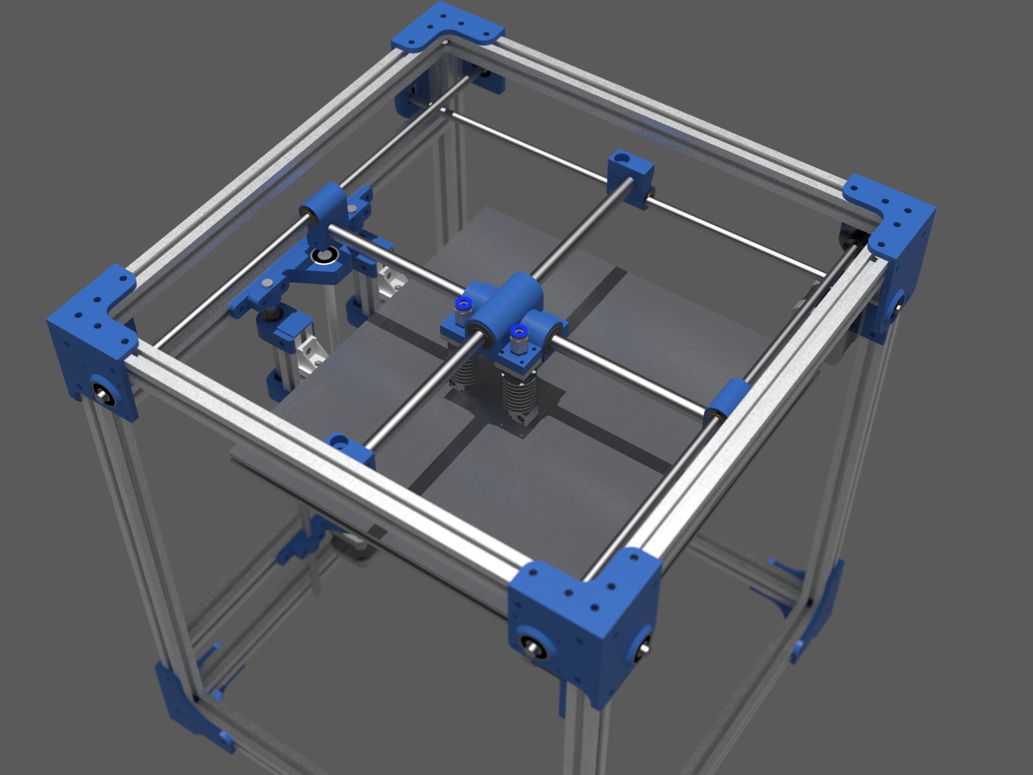
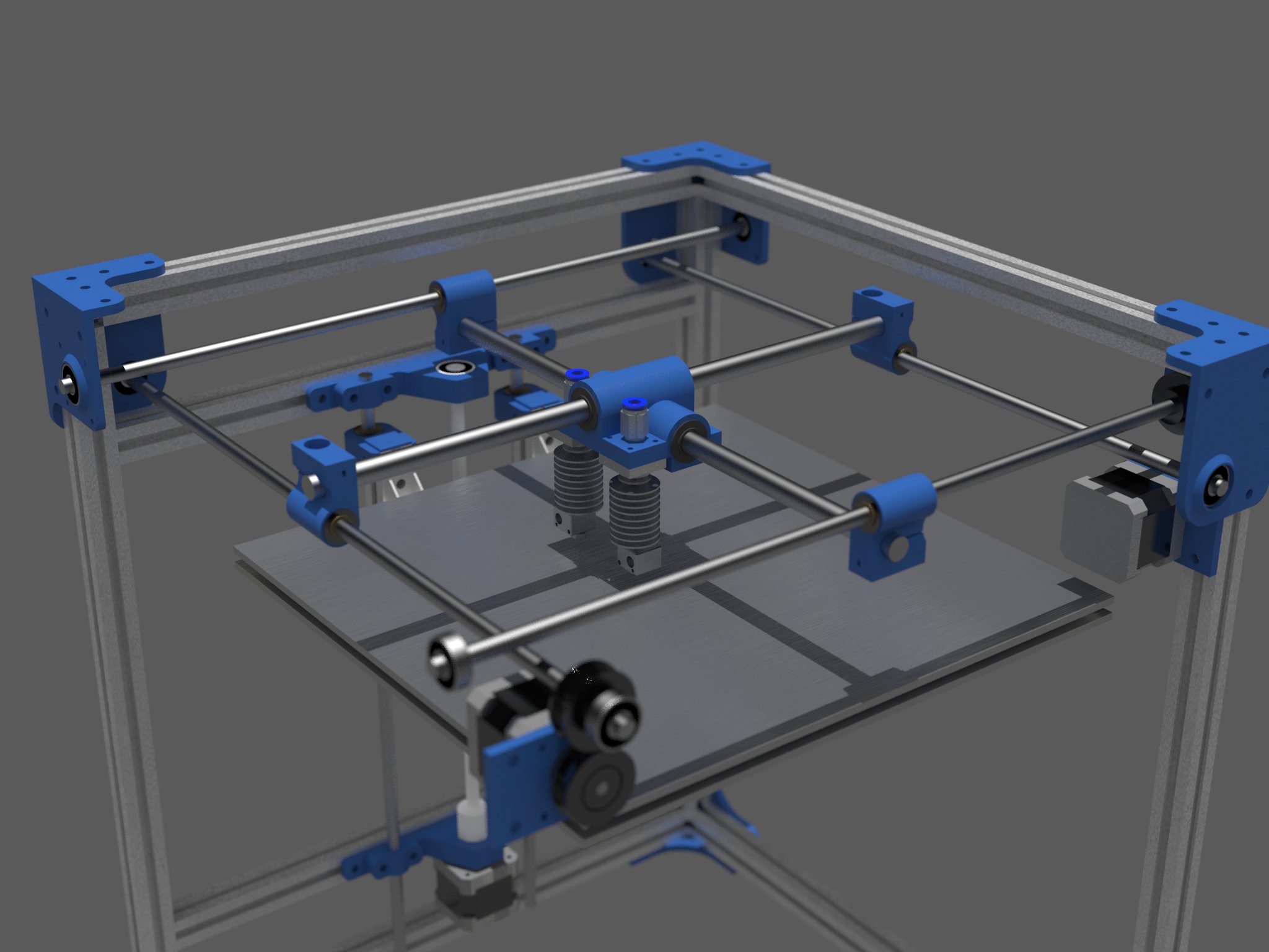
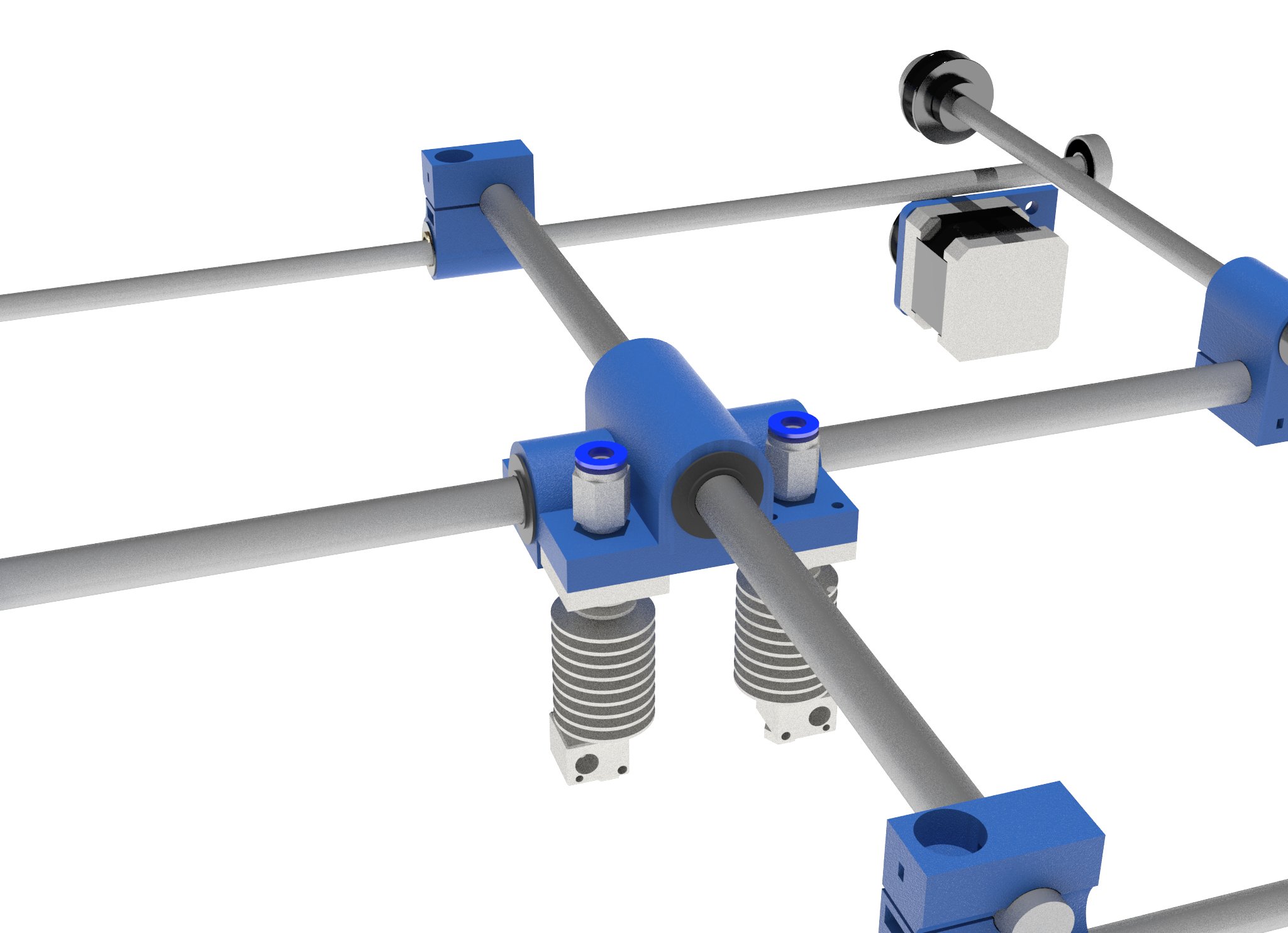
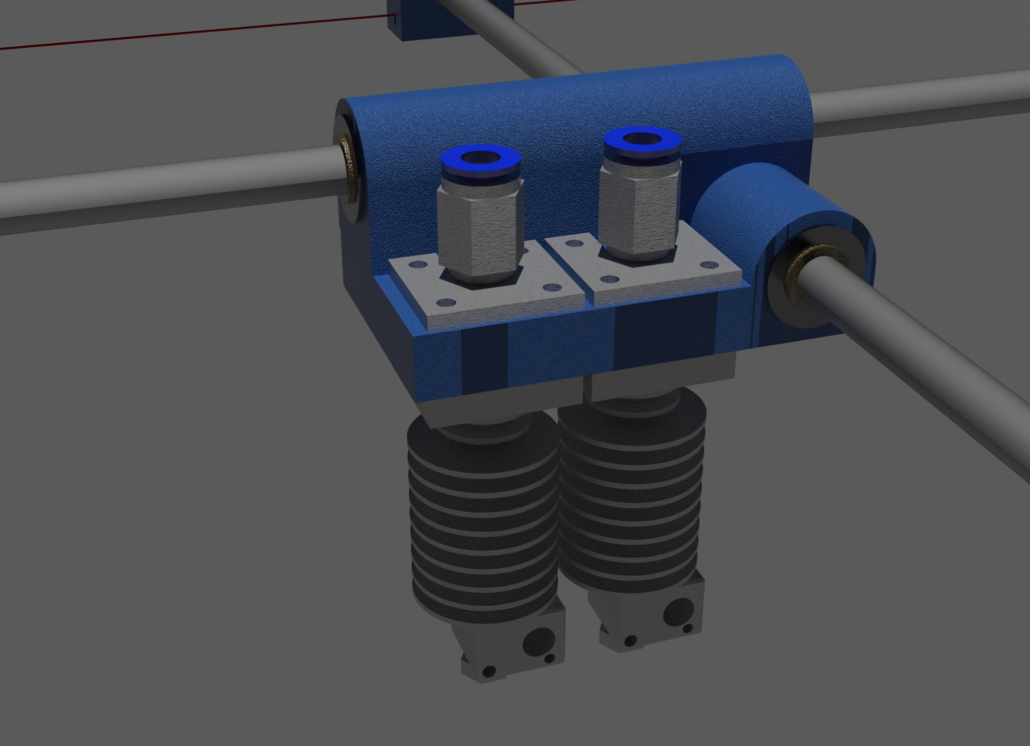
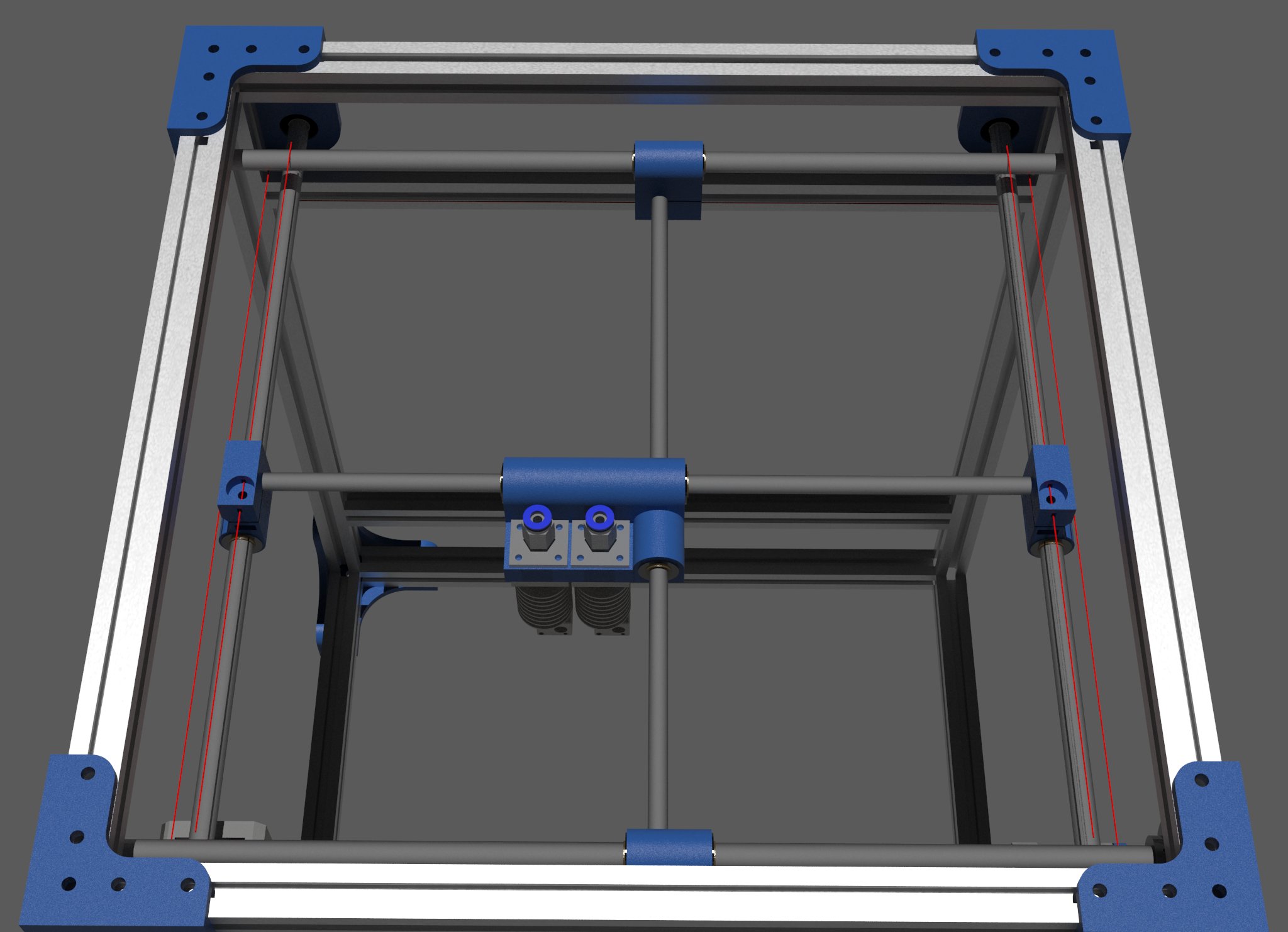
Sorry, only registered users may post in this forum.