Building a metric Variant
Posted by Helmi
|
Building a metric Variant August 28, 2013 06:31AM |
Admin Registered: 12 years ago Posts: 819 |
Hey,
i've been watching the Tantillus project since it's early days when the Indiegogo campaign launched and since then haven't seen so much other printers that print with a quality like Tantillus does with a size as small as 20x20x30cm. Great job, Sublime!
As i'm still searching for a small, low energy desktop printer for PLA only, Tantillus came back to my mind and i'm currently trying to find out the kinks for building one in Europe. As you might know imperial hardware is hard to get here so i'm looking for alternatives
I finally found some laser cutting services that can cut me some 6mm acrylic but it's more expensive than i thought. How much did it cost for you guys that already built an acrylic version? looks like it's around 100€ here (which is about 130$ USD). Going with the printed version is not an alternative for me as i'd like to have a beautiful piece on my desk and the acrylic version really looks neat.
I would guess that most of the screws are probably replaceable by metric screws with nearly the same size. Also the lead screw probably wouldn't be a problem as i'm thinking about going with the new cable version, but there are still some pieces where i'm unsure:
- the 5/16" rods need to be below 8mm to get the pushed into the bearings, right? do the 5/16" fit tight?
- is the acrylic meant to be 6mm?
-
more questions not related to metric/imperial
- i'd go with 1,75mm filament - anything that i need to watch besides the ptfe tubing, extruder and hotend?
- i'd like to use the reprapdiscount.com smart controller as a display - there should be enough room to get it into the front after modifying the drawings? or is there anything in that room that i don't see on pictures and plans so far?
Well that's all i can imagine now. I hope someone with metric building experience can help here.
Thanks,
Frank
Frank
|
Re: Building a metric Variant August 28, 2013 07:47AM |
Registered: 12 years ago Posts: 14 |
Hi,
I am currently building a metric tantillus, just waiting on the fishing line coming from china!
For the printed parts I used the metric assembly files here [forums.reprap.org] some of the nut traps required a bit of modification as I mostly had m3 hardware and it mainly uses m4. If youve got solidworks most of the legwork has been done which is great!
All the panels are ment to be 6mm except the small part which is sed to hold the hotend in place, although I reckon this could be printed in ABS and youd get away with it.
Indieflow on emaker> [www.emakershop.com] sells panels, I bought some wood ones from him which were ok quality wise, took a while to arrive as he was on holiday, but overall completly usable.
The rods is slightly complicated, for mine I used 8mm steel "tool rod" for the plastic bearings which I got with a prusa kit ages ago. And for the linear LM8uu bearings I used stainless steel 8mm "linear shafting" which came in with a OD of ~7.95mm which seemed to work fine. I think it really depends what you have available, the only reason I didn't use the stainless steel rod all round was cost.
Dont know much about 1.75mm filament or the LCD controller sorry!
|
Re: Building a metric Variant August 28, 2013 09:34AM |
Admin Registered: 12 years ago Posts: 819 |
Hey Mk,
thanks for the input. M4 isn't a problem at all, i'm luckily also not looking at costs soo much.
Thanks for the link to emakershop - that looks rather good but i guess that won't work if i change plans for the LCD and the Encoder - i'll probably contact them.
Regarding the rods i'll talk to the vendor i have for them - maybe they can tell me about tolerances.
Thanks for your help so far,
Frank
Frank
|
Re: Building a metric Variant August 28, 2013 12:15PM |
Registered: 13 years ago Posts: 2,947 |
Someone else used the larger display in their Tantillus by using Lajos' updated Marlin for Tantillus.
The only thing you may need to look at for the 1.75 filament is the hobbed bolt does not need to be as deeply grooved.
The only thing you may need to look at for the 1.75 filament is the hobbed bolt does not need to be as deeply grooved.
| FFF Settings Calculator | Gcode post processors | Geometric Object Deposition Tool Blog |
| Tantillus.org | Mini Printable Lathe | How NOT to install a Pololu driver |
|
Re: Building a metric Variant August 29, 2013 01:09PM |
Registered: 10 years ago Posts: 35 |
|
Re: Building a metric Variant August 29, 2013 01:13PM |
Admin Registered: 12 years ago Posts: 819 |
ok guyse i guess you got me wrong
I know how this technically works (btw it's Plug'n'play in Repetiers FIrmware as well which i prefer) but i was asking myself if it would fit in the case if i change the case drawings before cutting them or if there's probably something in this space behind the lcd that blocks the room (and i don't see that on the pictures).
Frank
|
Re: Building a metric Variant August 29, 2013 02:03PM |
Registered: 10 years ago Posts: 35 |
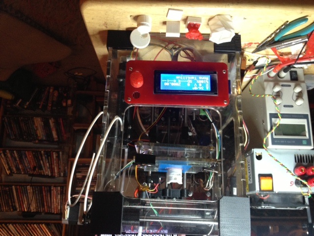
There is enough room for the LCD if you insert the LCD from the back to the front.. I had to laser cut a new hole in the front of a pre cut panel so the old LCD hole is still there. I covered it with that red panel. Also you need to cut an access hole in the side panel to access the SD Card.
|
Re: Building a metric Variant August 29, 2013 02:11PM |
Admin Registered: 12 years ago Posts: 819 |
|
Re: Building a metric Variant August 29, 2013 06:12PM |
Registered: 14 years ago Posts: 47 |
|
Re: Building a metric Variant September 03, 2013 04:01AM |
Admin Registered: 12 years ago Posts: 819 |
One more thing:
Regarding the 5/16" rods i think i can go with standard 8mm and (if needed) use my friends lathe to bring down the ends to fit into the 608 bearings. But i still wonder if it's a good way to go with the self printed bearings - couldn't they be replaces with standard linear bearings or even bether with the linear gliders from IGUS? The latter would probably be a problem as they have an outer diameter that is 1mm bigger than the LM8UU.
What do you think?
Frank
|
Re: Building a metric Variant September 03, 2013 06:02PM |
Registered: 12 years ago Posts: 14 |
|
Re: Building a metric Variant September 04, 2013 03:55AM |
Admin Registered: 12 years ago Posts: 819 |
|
Re: Building a metric Variant September 05, 2013 08:10AM |
Registered: 11 years ago Posts: 23 |
I have used standard 8mm rods for all elements. Worked with no lathe, but a drill, sand paper and loads of patience. Fully metric Tantillus is up and running happily for few months.
Having done that, however, now I would go the easy way now and buy 5/16" rods for the x-y axis. Saves you loads of time and makes assembly substantially faster. If you have access to a lathe I would do what @cfellows did - [forums.reprap.org] - e-clip to keep the rods nicely in place.
Having done that, however, now I would go the easy way now and buy 5/16" rods for the x-y axis. Saves you loads of time and makes assembly substantially faster. If you have access to a lathe I would do what @cfellows did - [forums.reprap.org] - e-clip to keep the rods nicely in place.
|
Re: Building a metric Variant September 06, 2013 01:10AM |
Registered: 14 years ago Posts: 47 |
|
Re: Building a metric Variant September 07, 2013 02:27PM |
Admin Registered: 12 years ago Posts: 819 |
I already aquired some e-clips (just a mixed box as i didn't have any so far) and think that shouldn't be a problem - don't have a lathe myself yet but a friend of mine has one and also has plenty of experience with it.
Another question is still making me think: gears or belts (or anything else). I'm a fan of quiet and smooth running printers and as far as i could seem from videos the gears are the foremost noisemakers on the Tantillus - is that right? I already saw some guys using belts there? a also have plenty of GT2 belts and pulleys laying around - only 5mm pulleys but that could be fixed - only real problem i have is that i don't have endless belts of such a short length that would be needed here and i have no idea where to get them or how to fix that otherwise.
What else came to my mind: why not use the fishing rods here, too? should be possible, hm?
I'd be happy to hear your ideas. What do you think about the noise issue? I also don't like the big gears so much from an optical point of view.
Frank
|
Re: Building a metric Variant September 07, 2013 11:17PM |
Registered: 10 years ago Posts: 35 |
|
Re: Building a metric Variant September 08, 2013 03:38AM |
Admin Registered: 12 years ago Posts: 819 |
|
Re: Building a metric Variant September 08, 2013 10:17AM |
Registered: 10 years ago Posts: 35 |
|
Re: Building a metric Variant September 24, 2013 10:57AM |
Registered: 11 years ago Posts: 290 |
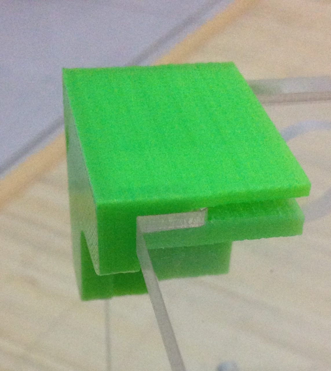
Hi, am building a Tantillus metric variant now. I got my acrylic laser cut and now printing the parts. Started with the corner_bottom. Its real tight and need to file a bit. My first two prints unusable because it just fit for 5mm acrylic. So then I recalibrate my Prusa until good enough.
Now, I am pushing this coner_bottom part, questions is how far shall I push this. I attach the picture for reference, is that enough or shall I push it to the end?
Now, I am pushing this coner_bottom part, questions is how far shall I push this. I attach the picture for reference, is that enough or shall I push it to the end?
|
Re: Building a metric Variant September 24, 2013 01:12PM |
Registered: 13 years ago Posts: 2,947 |
Looks close but I think it should go on a little more.
Depending on the machine it may be worth scaling the corners up by 1 - 2 percent.
Depending on the machine it may be worth scaling the corners up by 1 - 2 percent.
| FFF Settings Calculator | Gcode post processors | Geometric Object Deposition Tool Blog |
| Tantillus.org | Mini Printable Lathe | How NOT to install a Pololu driver |
|
Re: Building a metric Variant September 24, 2013 07:29PM |
Registered: 14 years ago Posts: 47 |
You can use hot tap water on PLA parts to soften them a bit and allow some flex, to fit things together that are otherwise too snug. It also causes the plastic to expand somewhat so better to try this with parts that fit on the outside of something else. This works great also for working loose things like Emmett's Gear Bearing that are articulated but printed in one piece. A good temp to try is ~100-110F or ~40C, but it varies based on the particular formulation of your plastic. Keep in mind that PLA is a relatively poor thermal conductor so it will need some time to warm up. For fitting those corners I would suggest starting with a 1 minute soak in a bowl of 100F warm water then trying the fit. They should slip on much easier, though they will contract some when cool which can make them quite difficult to remove.
Also you probably don't want to do this with parts that contact things that would be harmed by water as printed PLA can trap moisture, causing rust, electrical shorts or water damage to / swelling of wood.
Also you probably don't want to do this with parts that contact things that would be harmed by water as printed PLA can trap moisture, causing rust, electrical shorts or water damage to / swelling of wood.
|
Re: Building a metric Variant October 01, 2013 06:39AM |
Registered: 11 years ago Posts: 290 |
Thanks for the tip, I will try it later for the top parts. For now I file and gave the bottom parts two punches until fit perfectly.
Now printing other parts and hit this issue and with similar parts (having large horizontal hole). On very slope edge, the outermost perimeter just felt and did not stick to its adjacent perimeter. I am thinking if that could be because less overlap between adjacent perimeters. I sliced it with KS, 0.49mm perimeter width using 0.35mm nozzle. Shall we use support structure for printing this part? Or anyway we can add more overlap between perimeters?
Thanks.
|
Re: Building a metric Variant October 01, 2013 11:42AM |
Registered: 13 years ago Posts: 2,947 |
Those should be printed in the orientation the files are supplied. Or in other words vertically.
| FFF Settings Calculator | Gcode post processors | Geometric Object Deposition Tool Blog |
| Tantillus.org | Mini Printable Lathe | How NOT to install a Pololu driver |
|
Re: Building a metric Variant October 01, 2013 11:46AM |
Registered: 14 years ago Posts: 47 |
|
Re: Building a metric Variant October 01, 2013 04:40PM |
Registered: 10 years ago Posts: 36 |
Helmi Wrote:
-------------------------------------------------------
> I finally found some laser cutting services that
> can cut me some 6mm acrylic but it's more
> expensive than i thought. How much did it cost for
> you guys that already built an acrylic version?
> looks like it's around 100€ here (which is about
> 130$ USD). Going with the printed version is not
> an alternative for me as i'd like to have a
> beautiful piece on my desk and the acrylic version
> really looks neat.
>
I've just completed a mainly metric version using an Indieflow acrylic case from Emaker. As I had no access to a printer, he also sold me a set of imperial printed parts. I created a BOM from information on Tantillus.org and Willworkforplastic's metric design. It is pretty straightforward to source equivalent metric hardware in M3, M4 and M5. I did use 4 1/2" UNC for the hobbed bolt and 1/4 stainless for the Z axis. The metric hardward works OK with the imperial plastic parts, though some of the nuts need assistance to lock in their captive pockets. This make tensioning the lower cables a bit frustrating. Now I have the printer working I intend to make mertic parts for these areas.
Here are the metric equivalents I used. The numbers include spares:
Number Imperial Metric
20 off 10-32 x 3/4" M5 x 20 Socket head cap screws
8 off 8-32 x 1-1/2" M4 x40 Socket head cap screws
10 off 8-32 x 1" M4 x25 Socket head cap screws
10 off 8-32 x 3/4" M4 x20 Socket head cap screws
2 off 6-32 x 2" M3 x50 Socket head cap screws (needed to use M3 washers to be able to tighten down all the way. )
6 off 6-32 x 1-3/4" M4 x45 Socket head cap screws
12 off 4-40 x 3/4" M3 x20 Socket head cap screws
20 off M3 x10 Socket head cap screws
10 off 8-32 x 3/8" M4 x10 grub screws
4 off 4-40 x 1/4" M3 x6 grub screws
20 off 10-32 M5 Hex nuts
40 off 8-32 M4 Hex nuts
10 off 6-32 M3.5 Hex nuts
20 off 4-40 M3 Hex nuts
6 off 1/4"-18 M6 Hex nuts
4 off 5/16"-18 M8 Hex nuts
40 off #8 SAE M4 Flat washers - std flat washers?
4 off 1/4"-20 M8 Flat washers (or 5/16" needs to have 8mm hole)
2 off 5/16"-18 x 4-1/4" (or 4") M8 x110 (or 100mm) Bolt I acually used 4 1/2" in the end packed out with washers. 100mm was too short for me.
2 off 6.5mm i.d. x 20mm Spring (stronger is better)
5 off 4mm i.d. x 20mm Springs
25 off M3 Flat washers
> I would guess that most of the screws are probably
> replaceable by metric screws with nearly the same
> size. Also the lead screw probably wouldn't be a
> problem as i'm thinking about going with the new
> cable version, but there are still some pieces
> where i'm unsure:
>
> - the 5/16" rods need to be below 8mm to get the
> pushed into the bearings, right? do the 5/16" fit
> tight?
Yes. I bought 8mm and 5/16" silver steel ground bar from Ebay UK seller. Comes in 333mm lengths.
> - is the acrylic meant to be 6mm?
Ideally
>
> more questions not related to metric/imperial
>
> - i'd like to use the reprapdiscount.com smart
> controller as a display - there should be enough
> room to get it into the front after modifying the
> drawings? or is there anything in that room that i
> don't see on pictures and plans so far?
>
The two line 1602 display is fine IMO and fits in with the compact nature of the Tantillus. V Cheap from China. I did have some fun trying to work out how to wire it thi the RAMPS though.
|
Re: Building a metric Variant October 01, 2013 06:57PM |
Registered: 14 years ago Posts: 47 |
With regards to 8mm rods fitting into 608 bearings -- it may or may not work depending on both your rod and your bearings.
Rod tolerance can be either +/- some diameter, oddly the cheaper stuff is typically specified with just a minus tolerance (e.g. 8mm -.05mm) and so if it is on the lower end of the tolerance range it works fine. Precision ground rod for example may be +- .01mm and may be an extremely tight fit. Stainless steel rod seems to often be specified with just a - tolerance and so would generally work, but again not always.
If you're using linear ball bearings you need to choose appropriate rods else you will wear grooves in your rods in short order.
Same thing with bearings, they *should* be 8mm with + tolerance, and good quality bearings are pretty good about this, but not always. I had some super cheap ebay bearings that measured 7.95mm bore and wouldn't fit on any of the 8mm rod I had.
5/16" rod measures nominally 7.94mm and even with +/- tolerance should fit in a 608 bearing.
Sorry, only registered users may post in this forum.