Banding and failed/successful hacks to resolve it
Posted by willworkforplastic
|
Banding and failed/successful hacks to resolve it December 28, 2013 10:30PM |
Registered: 11 years ago Posts: 111 |
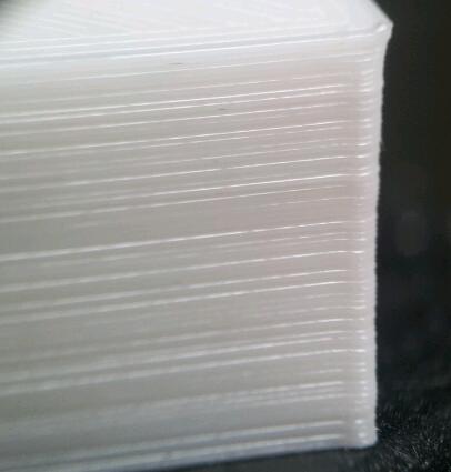
So from day one I have been chasing the cause of this banding I am seeing on my models under the microscope. A part from way back under the microscope looks like this:
So far here are the hacks I have tried on my Tantillus most are to try and stop this banding issue some. Some are just to be thorougher in this post:
- Running on 19V since day one
- 5V switcher on Audrino to handle higher supplier voltage
- Extra low ESD caps on the supply pins of the pololu stepper motor sockets on the RAMPS board
- Pololu black edition stepper drivers with heatsinks and fans
- Solvent welded the Acrylic outer case together
- Put gussits into Acrylic case
- Re-made the Z arms really solid and put long series linear bearing bushes in them
- Heated bed
- 6mm X 1.0 ball screw for Z axis, tried about 3 different types of couplers and solid motor coupler
- Glued the z lift in place to avoid any Z axis play (stupid move in hindsight)
- Running GT2 pulleys and belts instead of printed gears
- Removed MOV's from ramps and replaced with fuses to try and get better regulated supply voltage
- Nylon and ABS printed gears
- Tried the Sanyo denki steppers of ebay, disassembled and re-wired into parallel bipolar, helped but they vibrated like crazy. Probably because I rewired to parallel bipolar, running really hot also.
- Wantai 0.9 degree stepper motors on X/Y
- Tried the DRV8825 stepper driver from pololu but reverted back to A988
- Currently running 0.9 Wantai steppers on X/Y, 1.8 Wantai on Extruder and 1.8 Sanyo on Z axis
I checked the Z-axis with a DTI and at the moment my Z axis when it moves 0.1mm it is within +/-0.01mm and over a few millimeters it is +/-0.03mm.
It then dawned on me, with my X/Y step-up i am running about 240 pulses/mm or in full step 15 pulses/mm, or about 0.07mm per discrete pulse on the stepper motor if it was in full step mode. Now friends and colleges have explained to me that micro stepping can be tricky as you are balancing the motor between two discrete steps in the motor if it has not stopped on a discrete stop. The wave I was getting was about 0.05-0.1mm so made me think the two are related. I thought eh, its worth a shot I'll blindly f with the motion parameters in the configuration file. So at first I used:
DEFAULT_AXIS_STEPS_PER_UNIT {240.445,240.445,1600,430}
DEFAULT_MAX_FEEDRATE {70, 70, 2, 40}
DEFAULT_MAX_ACCELERATION {1000,1000,2,500}
DEFAULT_ACCELERATION 1000
DEFAULT_XYJERK 10
DEFAULT_ZJERK 1.0
DEFAULT_EJERK 25.0
Then printed a 20X20X50mm cube, 0.1mm layer @40mm/s printing according to KISSLICER (I must have printed 50 of these trying different things) the result was not good:
I though all hope was lost but then I thought why not really wind the X/Y acceleration down on the motion menu halfway through the print. So they got wound down to 5, which I assume is 500 in the DEFAULT_MAX_ACCELERATION line. Things suddenly got good:
So I re flashed the audrino with 500 in the DEFAULT_MAX_ACCERLERATION line for X/Y, wound the speed up to 120% in the Tune menu and printed away. The result was good and the same as the above picture.
The things I have left to do/try now:
- Is re-grease the X/Y bearings just to make sure they are really free moving. They feel it but want to be sure.
- Try a reducing ratio from the motor to the drive shaft say 4:1. Hopefully less torque on motor and discrete motor steps are finer travel.
- Read/research what these motion parameters in the configuration file. I was never any good at understanding motion control though........
- Look to see if there has been any improvements in marlin regarding motion, doubt it but I should check
So my question is does it sound like I am on the correct path? I gotta ask as it feels like I am standing so close to the wall I can no longer read the writing on it......................

So far here are the hacks I have tried on my Tantillus most are to try and stop this banding issue some. Some are just to be thorougher in this post:
- Running on 19V since day one
- 5V switcher on Audrino to handle higher supplier voltage
- Extra low ESD caps on the supply pins of the pololu stepper motor sockets on the RAMPS board
- Pololu black edition stepper drivers with heatsinks and fans
- Solvent welded the Acrylic outer case together
- Put gussits into Acrylic case
- Re-made the Z arms really solid and put long series linear bearing bushes in them
- Heated bed
- 6mm X 1.0 ball screw for Z axis, tried about 3 different types of couplers and solid motor coupler
- Glued the z lift in place to avoid any Z axis play (stupid move in hindsight)
- Running GT2 pulleys and belts instead of printed gears
- Removed MOV's from ramps and replaced with fuses to try and get better regulated supply voltage
- Nylon and ABS printed gears
- Tried the Sanyo denki steppers of ebay, disassembled and re-wired into parallel bipolar, helped but they vibrated like crazy. Probably because I rewired to parallel bipolar, running really hot also.
- Wantai 0.9 degree stepper motors on X/Y
- Tried the DRV8825 stepper driver from pololu but reverted back to A988
- Currently running 0.9 Wantai steppers on X/Y, 1.8 Wantai on Extruder and 1.8 Sanyo on Z axis
I checked the Z-axis with a DTI and at the moment my Z axis when it moves 0.1mm it is within +/-0.01mm and over a few millimeters it is +/-0.03mm.
It then dawned on me, with my X/Y step-up i am running about 240 pulses/mm or in full step 15 pulses/mm, or about 0.07mm per discrete pulse on the stepper motor if it was in full step mode. Now friends and colleges have explained to me that micro stepping can be tricky as you are balancing the motor between two discrete steps in the motor if it has not stopped on a discrete stop. The wave I was getting was about 0.05-0.1mm so made me think the two are related. I thought eh, its worth a shot I'll blindly f with the motion parameters in the configuration file. So at first I used:
DEFAULT_AXIS_STEPS_PER_UNIT {240.445,240.445,1600,430}
DEFAULT_MAX_FEEDRATE {70, 70, 2, 40}
DEFAULT_MAX_ACCELERATION {1000,1000,2,500}
DEFAULT_ACCELERATION 1000
DEFAULT_XYJERK 10
DEFAULT_ZJERK 1.0
DEFAULT_EJERK 25.0
Then printed a 20X20X50mm cube, 0.1mm layer @40mm/s printing according to KISSLICER (I must have printed 50 of these trying different things) the result was not good:

I though all hope was lost but then I thought why not really wind the X/Y acceleration down on the motion menu halfway through the print. So they got wound down to 5, which I assume is 500 in the DEFAULT_MAX_ACCELERATION line. Things suddenly got good:

So I re flashed the audrino with 500 in the DEFAULT_MAX_ACCERLERATION line for X/Y, wound the speed up to 120% in the Tune menu and printed away. The result was good and the same as the above picture.
The things I have left to do/try now:
- Is re-grease the X/Y bearings just to make sure they are really free moving. They feel it but want to be sure.
- Try a reducing ratio from the motor to the drive shaft say 4:1. Hopefully less torque on motor and discrete motor steps are finer travel.
- Read/research what these motion parameters in the configuration file. I was never any good at understanding motion control though........
- Look to see if there has been any improvements in marlin regarding motion, doubt it but I should check
So my question is does it sound like I am on the correct path? I gotta ask as it feels like I am standing so close to the wall I can no longer read the writing on it......................
|
Re: Banding and failed/successful hacks to resolve it December 28, 2013 11:35PM |
Registered: 13 years ago Posts: 2,947 |
Very interesting results.
When I look at the pictures I notice a couple other things.
1) The good print still has the same pattern being repeated along Z just a lot smaller but at the same frequency which implies to me that it is still the z axis causing the issue.
2) The corner of the good print is much rounder which could be hiding ripples a little.
I am having a hard time seeing how the X/Y acceleration could change the Z artifacts.
A lot of people with Mendel variant machines swear you need to run a layer height that is a multiple of full steps. I never found it was needed for my machines but maybe that has to do with the imperial lead screw? Have you tried running Z with full steps enabled and a layer height that is cleanly divisible by the mm/step?
| FFF Settings Calculator | Gcode post processors | Geometric Object Deposition Tool Blog |
| Tantillus.org | Mini Printable Lathe | How NOT to install a Pololu driver |
|
Re: Banding and failed/successful hacks to resolve it December 29, 2013 02:38AM |
Registered: 11 years ago Posts: 111 |
I to am too having trouble understanding why the X/Y acceleration helped with this.
A full step on my Z is 0.005mm so I will give running it in full step a go and see how it goes, it sounds to me like a more plausible solution to me. One other theory I have is that the step rate/frequency gets high then the audrino cannot handle it and funny things happen. So lowering the step/mm could be a good thing for loading on the audrino, though I really do not know enough about these things to make good theories up.
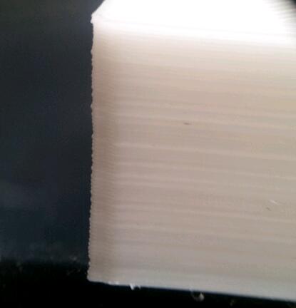
Here is something else interesting on the banding, if you look at one side then carefully draw a line across the print to the other side it shows the layer is just larger all around, like the Z has not moved correctly to the right distance:
Also you are right about the corners:
Looks like a larger corner radius hiding the issue.
I might also try and DTI the Z axis while it is running and see if it actually moving the correct distance.
A full step on my Z is 0.005mm so I will give running it in full step a go and see how it goes, it sounds to me like a more plausible solution to me. One other theory I have is that the step rate/frequency gets high then the audrino cannot handle it and funny things happen. So lowering the step/mm could be a good thing for loading on the audrino, though I really do not know enough about these things to make good theories up.
Here is something else interesting on the banding, if you look at one side then carefully draw a line across the print to the other side it shows the layer is just larger all around, like the Z has not moved correctly to the right distance:

Also you are right about the corners:

Looks like a larger corner radius hiding the issue.
I might also try and DTI the Z axis while it is running and see if it actually moving the correct distance.
|
Re: Banding and failed/successful hacks to resolve it December 29, 2013 07:51PM |
Registered: 13 years ago Posts: 2,947 |
I would agree that too high of step rate could cause the Arduino to have issues but the Z axis is not combined with X and Y moves so Z moves should not be effected by X and Y. Another test you could do is to reduce the Z jerk to 1 and lower the Z acceleration. This should make the z move at a more or less constant rate. This may cause a bump where the hotend sits while it is moving up because of ooze. But if the issue with bands goes away you could then increase the settings slowly until you find the point it comes back.
For my own reference how do these prints compare to the gears I sent you?
From all the pictures it still looks like a Z lead screw issue. Would you consider trying a cable Z to see if the issue goes away?
Another thought is maybe this has to do with axial play in the motor shaft? Maybe your heavier bed is causing an issue that only shows up at certain angles of motor rotation? They are not designed to carry a load the way we are using them. Have you thought about supporting the bottom of the lead screw with a thrust bearing? It could be a spacer that sits on top of the motor with the thrust bearing on it and a washer on top of it with the lead screw coupler sitting on the washer.
Also the reason for the high acceleration rates is to get the sharp corners.
Edited 1 time(s). Last edit at 12/29/2013 07:52PM by Sublime.
| FFF Settings Calculator | Gcode post processors | Geometric Object Deposition Tool Blog |
| Tantillus.org | Mini Printable Lathe | How NOT to install a Pololu driver |
|
Re: Banding and failed/successful hacks to resolve it December 30, 2013 12:13AM |
Registered: 11 years ago Posts: 290 |
Could that be due to motor resonance?
I had similar issue on my Prusa. Lowering the speed/acceleration only make it less visible but still there if taken look closely.
Then I changed my X Y motor to Sanyo Denki 0.9deg/step with a dumper in the back of the motor. It gives me far better result even at higher speed I used to have the issue.
You said tried DRV825 motor driver then back to A988. Is there any issue with DRV825? I actually want to buy that one.
|
Re: Banding and failed/successful hacks to resolve it December 30, 2013 03:33AM |
Registered: 10 years ago Posts: 87 |
My prints are nowhere near as good as what you have shown but I do have some comments. It's really great to see all your modifications on one page. It would be nice to quantify the improvements that each made. One in particular is if you plug a regular 12 volt power pack into your machine now and compare a test print, how much difference is there? This could be motivating to up my voltage, possibly an easy thing for you to try.
My banding is really bad and is mostly due to z wobble. I did a couple of mods to my z axis and the banding is 80% gone. My 20% is probably sitll worse than yours. I have not fully tested to see if there are any issues with what I have done either but I am posting it for interest.
You can see the before(left) and after(right). Yes my camera is shitty sorry.
http://www.edns.co.nz/tantillus/banding/head_banding.jpg
And my two mods.
Mod1: Replace the coupler with 4mm ID silicone hose. This worked really well and is much more compliant than any proper couplers. I made sure there was an air gap of 2 to 3mm between the motor shaft and threaded rod. I also jammed a cable tie down the motor shaft flat. It does not slip at all.
http://www.edns.co.nz/tantillus/banding/coupling.jpg
Mod2: This is dodgy. I took the top nut on the z lift and glued it so it would no longer be engaged and the spring is just floating on top now so the table is just resting on the nut by gravity instead of a spring. My bed is heated so it is heavier too. Note that I am doing z-lifts and am not seeing problems. The reason I did this is any shaft wobble would be transffered to the table as it is fixed by two points(nuts) one nut means it can float so the z wobble does not push the table anymore.
http://www.edns.co.nz/tantillus/banding/top_nut.jpg
My current fantasy is to have a lightweight filament feeder mounted on the print head as my biggest issues are blobs during z-lifts which tricky prints force me to do.
|
Re: Banding and failed/successful hacks to resolve it December 30, 2013 11:44AM |
Registered: 13 years ago Posts: 2,947 |
Quote
Robonz
My current fantasy is to have a lightweight filament feeder mounted on the print head as my biggest issues are blobs during z-lifts which tricky prints force me to do.
Do you find Z-lift is really needed? I have not used Z-lift since switching to Kisslicer and rarely ever used it before then.
I think I just realized what may be causing this banding on both your machines. I have read in the past that this is caused by the bed heating and cooling. With each heating and cooling cycle the bed expands and contracts. I would not have this issue since I do not run a heated bed.
Mayb the both of you could try printing a tall test cube and turn off the bed half way through and see if the problem goes away when is cools down.
Edited 1 time(s). Last edit at 12/30/2013 11:45AM by Sublime.
| FFF Settings Calculator | Gcode post processors | Geometric Object Deposition Tool Blog |
| Tantillus.org | Mini Printable Lathe | How NOT to install a Pololu driver |
|
Re: Banding and failed/successful hacks to resolve it December 31, 2013 10:22AM |
Registered: 10 years ago Posts: 80 |
I too have been getting pronounced banding. My only mods are belt drive for the X/Y and a spiral cut aluminum coupler for the Z. I just got done making and installing a new hobbed bolt and my first calibration cube is very promising (more testing tonight). My original must have been really bad because I could actually hear the difference. Much smoother sounding. I didn't know that the crunching and popping sounds from the extruder weren't normal :-). Will post a pic later today.
BTW: I think it would be really useful if we made it a habit of included something in the picture to give your print some scale. Also, for the sake of comparison, I propose that we standardize on 0.10 layer height.
Edited 2 time(s). Last edit at 12/31/2013 12:32PM by wingnut.
BTW: I think it would be really useful if we made it a habit of included something in the picture to give your print some scale. Also, for the sake of comparison, I propose that we standardize on 0.10 layer height.
Edited 2 time(s). Last edit at 12/31/2013 12:32PM by wingnut.
|
Re: Banding and failed/successful hacks to resolve it January 01, 2014 07:41PM |
Registered: 11 years ago Posts: 111 |
Right So I have Tried:
Machining Up a precision solid coupler and fitting (not a good idea as there is no float) between motor and lead screw
Putting 'thrust' bearing back in on top Z mount, I had taken it out to see if it would make a difference a while ago
Printing with heated bed off
Running Z really slowly (0.1mm/s, 0.05mm/s^2, jerk 0.05)
Swaping Z/Y motor plugs over and pin defs in pins.h
Moding firmware and putting 2uS delay in for step pulse, just to make sure it triggers the A988
Putting a DRV825 in running in full step
Using Slic3r 0.7.2b, print was really messy, but banding still existed (even in blobs.....)
And F'me the banding is still there and still has a pitch of 1mm. However when the lead screw spins there is no visible wobble. It looks true like some thing running in a lathe.
So I got my micron DTI out, clocked onto the glass and moved the bed in 0.1mm increments over a few millimeters and recorded relative move amounts. At worst case 100µm was 80µm or 125µm. So I CAD'ed up theoretical cross sections and the results where interesting. What I did was CAD the cross section of a 0.12mm layer with a track width of 0.22mm (I was using this to match something someone had printed and wanted a comparison, for the photo's above I never switched back to 0.1/0.35), measure the surface area then over laid the same xsection with smaller/bigger layer thickness and adjusted the track width to give the same surface area. The results where:
Red is theoretical and green is what you would get with Z axis movement error. Add the two differences in track width and you get 50µm, which is the same as what I am seeing. So the remaining things I think it could be caused by are:
Issue with motion control firmware or electronics missing and then gaining steps, but I would assume that other people would have found this also. So I am not going to bother exploring this yet (plus I sux at coding compared with the people who wrote marlin/sprinter etc)
Stepper resonating, but I assume this would show up as a more random phenomenon.
The pitch over 50mm on my ball screw is accurate (models come out to within +/-50µm) but the linearity over one pitch cycle is not so good. Probably this is the case, its a Taiwanese ball screw ($200) and not a Japanese one (probably over $500).
So I will start Cading up the Z-cable system and try that. It will take some time, but I'll post up results once I have some. Might try machining up drums/idlers also to see if this has any affect also.
@Sublime
Your gears look good, I tried photographing them for you but the photos are not so good. You will find them here. One has 0.15mm layer written on it and the track width is wide. However I would have assumed a wider track width would have made the problem much worse. So I think you have nothing to worry about. Might be something to do with the way imperial threaded rod is made compared with metric, or different suppliers etc.
Yeah I had a bad feeling about the ball screw, but I got it just before the Z cable system came out so I pushed on. I will try the cable system now and see how I go. If that is still no good I might look into a Japanese ball screw but that is mega expensive.
Yeah I had a support bearing on the top Z axis bracket, which I put back in, but it did not help. Photo here.
Tried printing with the heated bed off and banding still remains.
@zungmann
Thanks for the tip about the sanyo denki dampered motors. Found them on ebay and I will order some to try out.
As for the DRV825 the seem to work well, easier to heatsink and did not blow up like the A988 when I accidentally missed one of the pins off when I plugged a stepper cable in. I am not running them at the moment just to avoid confusing things. If you do go that way there is a bit of info about putting them into fast decay mode which some people seem to think is better. I will try them again once I have this banding sorted.
@wingnut
Yup I will changed back to 0.1mm layer height for the rest of this thread. As for track width I have no idea what is a good standard, maybe sublime can advise on this.
As for my photos above the yellow parts are 0.12mm layer height with 0.22mm track width. The banding is exactly 1mm pitch. It is a bit hard to get a scale under the microscope also, but I will see what I can do going forward.
@Robonz
I assume you can see the banding on the parts I gave you for your printer if you need a reference. If I get a chance once I have fixed the banding issue I can try running the printer of 12V. I would say the major difference will be the hot end will not get up to 240ish oC if you ever wanted to print Taulman Nylon or TGlass
@Anybody
I have attached the cube STL I have been using, feel free to try and print it at 0.1mm layer height and whatever track width we decide on for comparison sake. Post up photos of the results here as I would be keen to see what other people are getting.
Machining Up a precision solid coupler and fitting (not a good idea as there is no float) between motor and lead screw
Putting 'thrust' bearing back in on top Z mount, I had taken it out to see if it would make a difference a while ago
Printing with heated bed off
Running Z really slowly (0.1mm/s, 0.05mm/s^2, jerk 0.05)
Swaping Z/Y motor plugs over and pin defs in pins.h
Moding firmware and putting 2uS delay in for step pulse, just to make sure it triggers the A988
Putting a DRV825 in running in full step
Using Slic3r 0.7.2b, print was really messy, but banding still existed (even in blobs.....)
And F'me the banding is still there and still has a pitch of 1mm. However when the lead screw spins there is no visible wobble. It looks true like some thing running in a lathe.
So I got my micron DTI out, clocked onto the glass and moved the bed in 0.1mm increments over a few millimeters and recorded relative move amounts. At worst case 100µm was 80µm or 125µm. So I CAD'ed up theoretical cross sections and the results where interesting. What I did was CAD the cross section of a 0.12mm layer with a track width of 0.22mm (I was using this to match something someone had printed and wanted a comparison, for the photo's above I never switched back to 0.1/0.35), measure the surface area then over laid the same xsection with smaller/bigger layer thickness and adjusted the track width to give the same surface area. The results where:


Red is theoretical and green is what you would get with Z axis movement error. Add the two differences in track width and you get 50µm, which is the same as what I am seeing. So the remaining things I think it could be caused by are:
Issue with motion control firmware or electronics missing and then gaining steps, but I would assume that other people would have found this also. So I am not going to bother exploring this yet (plus I sux at coding compared with the people who wrote marlin/sprinter etc)
Stepper resonating, but I assume this would show up as a more random phenomenon.
The pitch over 50mm on my ball screw is accurate (models come out to within +/-50µm) but the linearity over one pitch cycle is not so good. Probably this is the case, its a Taiwanese ball screw ($200) and not a Japanese one (probably over $500).
So I will start Cading up the Z-cable system and try that. It will take some time, but I'll post up results once I have some. Might try machining up drums/idlers also to see if this has any affect also.
@Sublime
Your gears look good, I tried photographing them for you but the photos are not so good. You will find them here. One has 0.15mm layer written on it and the track width is wide. However I would have assumed a wider track width would have made the problem much worse. So I think you have nothing to worry about. Might be something to do with the way imperial threaded rod is made compared with metric, or different suppliers etc.
Yeah I had a bad feeling about the ball screw, but I got it just before the Z cable system came out so I pushed on. I will try the cable system now and see how I go. If that is still no good I might look into a Japanese ball screw but that is mega expensive.
Yeah I had a support bearing on the top Z axis bracket, which I put back in, but it did not help. Photo here.
Tried printing with the heated bed off and banding still remains.
@zungmann
Thanks for the tip about the sanyo denki dampered motors. Found them on ebay and I will order some to try out.
As for the DRV825 the seem to work well, easier to heatsink and did not blow up like the A988 when I accidentally missed one of the pins off when I plugged a stepper cable in. I am not running them at the moment just to avoid confusing things. If you do go that way there is a bit of info about putting them into fast decay mode which some people seem to think is better. I will try them again once I have this banding sorted.
@wingnut
Yup I will changed back to 0.1mm layer height for the rest of this thread. As for track width I have no idea what is a good standard, maybe sublime can advise on this.
As for my photos above the yellow parts are 0.12mm layer height with 0.22mm track width. The banding is exactly 1mm pitch. It is a bit hard to get a scale under the microscope also, but I will see what I can do going forward.
@Robonz
I assume you can see the banding on the parts I gave you for your printer if you need a reference. If I get a chance once I have fixed the banding issue I can try running the printer of 12V. I would say the major difference will be the hot end will not get up to 240ish oC if you ever wanted to print Taulman Nylon or TGlass
@Anybody
I have attached the cube STL I have been using, feel free to try and print it at 0.1mm layer height and whatever track width we decide on for comparison sake. Post up photos of the results here as I would be keen to see what other people are getting.
|
Re: Banding and failed/successful hacks to resolve it January 01, 2014 08:04PM |
Registered: 13 years ago Posts: 2,947 |
I do see a little banding in the gear photos but not nearly as consistent and could be the result of other factors like my filament diameter.
For 0.1mm layers my calculator says using a 0.5mm J-head to print at 0.49mm width and for a 0.5mm (not J-head) at 0.51mm width. So for comparison I would use 0.5 or 0.51 width. For my imperial lead screw machines I now use 0.136 layers and 0.52 (with a J-head). I use the calculator to determine my own settings with the exception that I often turn the speed up via the LCD.
You could do a simple test to see if the issue is the software. Write a small test program in Arduino to run the stepper x number of pulses, pause for long enough to take your measurement, take x number of steps again,,,,,,,,,,,,. Maybe add a button check to monitor the encoder button to run each step pulse routine at the push of a button.
| FFF Settings Calculator | Gcode post processors | Geometric Object Deposition Tool Blog |
| Tantillus.org | Mini Printable Lathe | How NOT to install a Pololu driver |
|
Re: Banding and failed/successful hacks to resolve it January 02, 2014 04:35AM |
Registered: 10 years ago Posts: 87 |
WWFP Great post, seeing the calcs is great. Thats a bit beyond me.
I am printing some of your test prints (0.4mm head with 0.41 extrusiuon width and 0.22 for another test) and will be happy to drop them over so I can see how far away my prints are from yours. 0.41 is from Sublimes calculator for optimium extrusion width using 0.1 layers 0.4 head and metric.
I learnt something today from one of Sublimes posts (clever guy). I was wondering about extrusion width. On your "yellow" picture above you can see your wall thickness is about double becuase you get the squiggly infill in between your loops and and sparse fill (I don't know if this is intentional). My prints were doing the same. It makes for slow printing. Changing my skin thickness from 2 to 1 sorted that out. I just found I get errors in Kisslicer if that number is bigger than about 1.6 or so e.g. one missing infill layer..
Sublimes post here:
http://forums.reprap.org/read.php?263,276307
Quote "Skin thickness is a funny setting since it sets the top and bottom thickness as well as the minimum wall thickness. So if you have two perimeters at 0.53mm wide I would set the skin thickness to 0.9 or 1. If it is set to a value higher than the width times the perimeter count it will add squiggly infill around the inside to make up the extra wall thickness which is not the best."
i am "keen as" to see what you come up with for a cable drive and captilise on your great work. Lunch shout or two?
I think a 1 nut solution on the z lift with a backlash counter measure for us using threaded rods would be an improvement to z wobble. like a tension spring or two between the bottom nut and the z lift part. i think your precision set up is probably way past that already though.
|
Re: Banding and failed/successful hacks to resolve it January 02, 2014 09:09PM |
Registered: 10 years ago Posts: 87 |
@willworkforplastic I printed that test print using 0.1 layer x 0.41 extrusion width.Here is a side by side photo of yours and mine. The pictures are not very good so I don't really have any opinions. I can give you the test print to look at if you like.
Light souce on the top
Light source on the left
The white plastic shows shadows more I noticed. My z woble is not a pronounced repeatable ripple like it was, but more random now. This may be due to backlash/stiction on the z travel having no top nut. With a top nut and a less compliant coupler I used to get more wobble on the prints with a repeatable 1mm ripple. I plan to add some backlash tension springs to see if I can reduce the random ripples a little more.
I would be keen to see other peoples prints especiclly with a cable z axis.
|
Re: Banding and failed/successful hacks to resolve it January 02, 2014 10:24PM |
Registered: 10 years ago Posts: 80 |
Here are some pics of the cube I printed after replacing my hobbed bolt. It's the nicest looking cube to come out of my printer. Crazy thing is that this is printed from an old slice I had laying around so I'm not really sure what parameters where used. I know it 0.1 layers and really slow. I've been trying some more difficult prints with 0.15 layers and so far they're ok but nothing like this. I have much to learn still regarding slicing parameters.
|
Re: Banding and failed/successful hacks to resolve it January 03, 2014 01:46AM |
Registered: 13 years ago Posts: 2,947 |
I will try and find some time to print the test cube on a cable Z machine and a imperial lead screw machine.
| FFF Settings Calculator | Gcode post processors | Geometric Object Deposition Tool Blog |
| Tantillus.org | Mini Printable Lathe | How NOT to install a Pololu driver |
|
Re: Banding and failed/successful hacks to resolve it January 26, 2014 08:50PM |
Registered: 11 years ago Posts: 111 |
So I have made up a cable Z lift setup.
I made the brackets a bit bulkier and machined the drum and upper idler to be sure they are circular from 7075 aluminium. I did change the drum diameter so that on the pitch circle of the cable I get 0.06mm per full step using a 0.9 deg stepper.
So I will not bore you with all the testing but just the result:
So It looks better.
Also I have changed out to these steppers on X/Y/Z. Bit of hacking required but the rotational dampers seem to stop a bit of the vibration especially at high speed. Thanks zungmann for suggesting.
I made the brackets a bit bulkier and machined the drum and upper idler to be sure they are circular from 7075 aluminium. I did change the drum diameter so that on the pitch circle of the cable I get 0.06mm per full step using a 0.9 deg stepper.
So I will not bore you with all the testing but just the result:

So It looks better.
Also I have changed out to these steppers on X/Y/Z. Bit of hacking required but the rotational dampers seem to stop a bit of the vibration especially at high speed. Thanks zungmann for suggesting.
|
Re: Banding and failed/successful hacks to resolve it January 27, 2014 12:09PM |
Registered: 13 years ago Posts: 2,947 |
It does look a little better but the effect is still there to some degree. Do you use Z-lift? Have you checked that it is not the firmware with a simple Arduino program sending a specific number of steps?
Quote
Sublime
You could do a simple test to see if the issue is the software. Write a small test program in Arduino to run the stepper x number of pulses, pause for long enough to take your measurement, take x number of steps again,,,,,,,,,,,,. Maybe add a button check to monitor the encoder button to run each step pulse routine at the push of a button.
| FFF Settings Calculator | Gcode post processors | Geometric Object Deposition Tool Blog |
| Tantillus.org | Mini Printable Lathe | How NOT to install a Pololu driver |
|
Re: Banding and failed/successful hacks to resolve it January 27, 2014 10:12PM |
Registered: 10 years ago Posts: 80 |
|
Re: Banding and failed/successful hacks to resolve it February 02, 2014 04:05AM |
Registered: 11 years ago Posts: 111 |
@Wingnut - Thanks, to the naked eye it does look really good and maybe I should just leave it at this........
@Sublime (sorry the reply has taken a while)
There was no Z-lift on these prints. Only thing is the cable print above was printed about 20% faster from memory.
The testing I did before those photos was:
Tried to DTI the glass bed in the machine with the ball screw in. Set the Z steps per mm to 10 so that when I press 0.1 in pronterface I would get one step in full step mode. Found something weird where I would press the 0.1mm button in pronterface but the Z axis would not move. I would have to press it 6 times then the stepper would move 6 pulses. So I tried your Marlin Tantilus variant of firmware and stock marlin. All the same. So I set things back to normal and edited your tantilus variant of firmware to count the pulses sent to the stepper driver and pump that out with what marlin thought the Z position was over the serial/usb to pronterface. It was perfect up to 50mm, so that basically adds another tick in the firmware is not the culprit here.
So I wrote a simple program which when I pressed the encoder button it moved the stepper. First case I set it to 10 steps per button press and DTI'ed the glass bed. I did not see an error greater than 20µm. Then I set up the cable drive on a granite surface plate and repeated the same test. No idea what the variance was as I have no crunched the numbers, but when I do I will post up what it was.
The only things I can think it can be now are:
1. Because I ran at a faster speed the X/Y positioning was off, though the wave looks to constant to me for it to be this.
2. I have noticed my extruder idler plate moves in and out when driving, which suggests to me that the hobbing on the bolt is not running concentric to the bolt OD. This I assume would lead to variance in extruded length as the bolt turns. I will turn up a 'bolt' with a straight knurl and see if this helps.
3. The filament diameter is varying, but somehow I doubt this is the case.
|
Re: Banding and failed/successful hacks to resolve it February 02, 2014 06:22AM |
Registered: 10 years ago Posts: 87 |
My idler was moing in and out on the extruder the other day too. It took me a while to find but it was the PLA binding in the bowden cable where my nut had compressed the bowden tube. The hobbed bolt indentations certainly reduce the clearance a lot as you know. I cleared the bowden with a needle file and she was happy again. I did do all this when I built the machine so I am not sure why I needed to do it again.
|
Re: Banding and failed/successful hacks to resolve it February 02, 2014 12:29PM |
Registered: 13 years ago Posts: 2,947 |
Quote
willworkforplastic
to the naked eye it does look really good and maybe I should just leave it at this........
Personally I would leave it.
| FFF Settings Calculator | Gcode post processors | Geometric Object Deposition Tool Blog |
| Tantillus.org | Mini Printable Lathe | How NOT to install a Pololu driver |
|
Re: Banding and failed/successful hacks to resolve it February 13, 2014 03:14AM |
Registered: 11 years ago Posts: 111 |
Quote
Sublime
Quote
willworkforplastic
to the naked eye it does look really good and maybe I should just leave it at this........
Personally I would leave it.
Yeah that is what I have done for now and the prints are coming out superb to the eye. I might just for interest sake make proper hobbed bolt just to see if it helps, but because I will have to get a gear cutter to make it, it will be a while off.
Sorry, only registered users may post in this forum.