|
Soldering Limit Switch on X Motor Assembly September 29, 2013 11:01PM |
Registered: 10 years ago Posts: 363 |
Sorry if this is a really simple question.
When setting up the X Motor Assembly I would like to leave the two wires running to the limit switch long to make soldering easier. Can I leave plenty extra? And then maybe coil it and tucking it away before attaching the limit switch to the housing?
Somehow I would feel happier with longer wires. I would like to use a helping hands device to hold this wire and switch while soldering; longer wires would make this easier. Also, if I ever need to replace the limit switch I would have more wire to work with.
Also, does it matter which wire goes to which prong on the switch?
Thank you
Garry
|
Re: Soldering Limit Switch on X Motor Assembly September 30, 2013 02:31AM |
Admin Registered: 17 years ago Posts: 7,879 |
A little longer shouldn't matter as long as you tie it back so it doesn't get tangled in the belt or the leadscrew.
You don't need to pass it through the hole in the bracket if you that makes it easier. It can just go over the top of the motor bracket and under the extruder cable.
No the polarity of switches doesn't matter as long as you use the outer two pins and ignore the middle one.
[www.hydraraptor.blogspot.com]
|
Re: Soldering Limit Switch on X Motor Assembly September 30, 2013 12:46PM |
Registered: 10 years ago Posts: 363 |
|
Re: Soldering Limit Switch on X Motor Assembly September 30, 2013 09:46PM |
Registered: 10 years ago Posts: 363 |
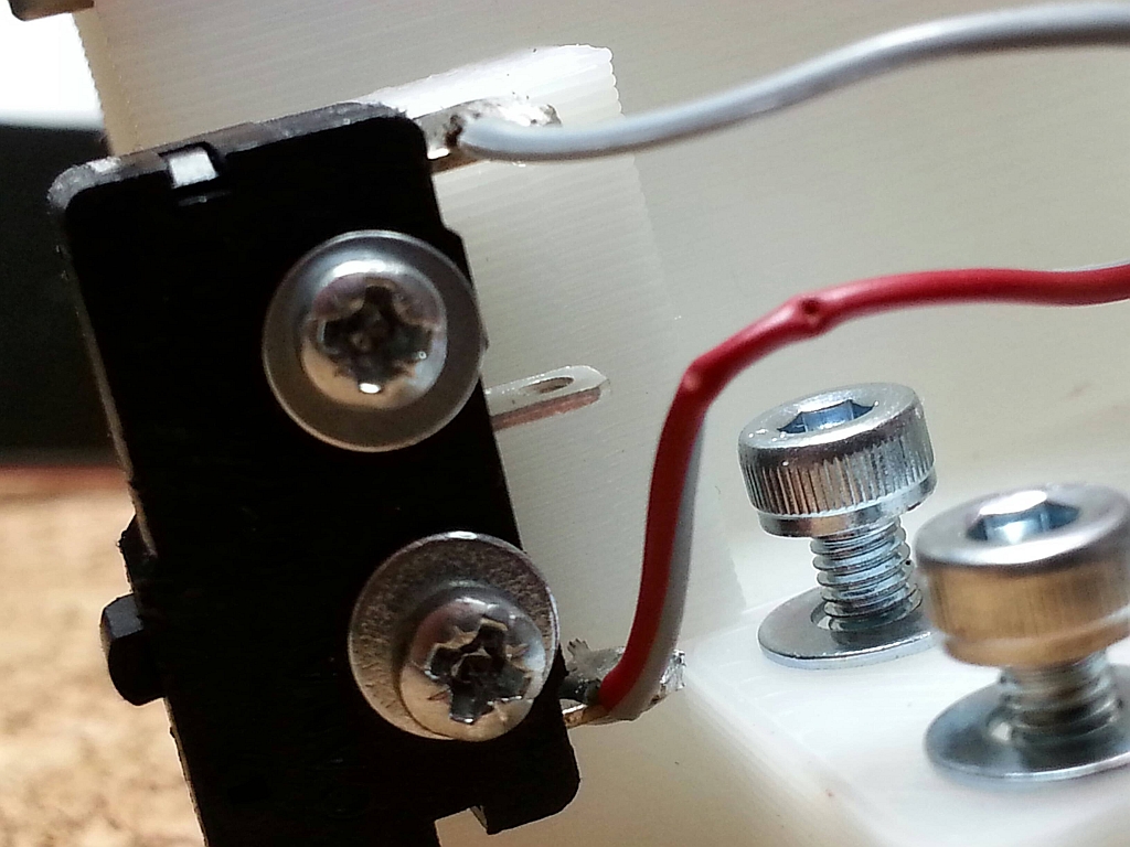
We soldered the switch but when it is installed the lower wire is under the screw head and will be crushed when the screw is tightened. Do others make this mistake? The only solution seems to re-flow the solder and mount the wire to the prong at a very steep angle to avoid the screw. Before doing so I'd like to show the problem in case someone has a better solutions for this problem. Thank you.
|
Re: Soldering Limit Switch on X Motor Assembly October 01, 2013 03:23AM |
Registered: 11 years ago Posts: 369 |
It looks like you have threaded the wire through the holes in the switch prongs and twisted them back on themselves? I don't think you really need to do that - a good, compact solder joint will be secure enough. By only stripping the last few mm of insulation to solder the wire to the switch the rest of the wire should still be flexible enough to bend away from the screws, plus you will have less exposed wire that could potentially short etc.
|
Re: Soldering Limit Switch on X Motor Assembly October 01, 2013 03:51AM |
Registered: 10 years ago Posts: 301 |
Hi,
look here what I did.
Regards
MfG / Regards
Stefan
Blog / Gallery / Wiki / Mendel90 kit since Sep 2013 from Nophead / Original Prusa I3 MK3 since Feb 2018 /
OpenScad Workshop: Kursdateien
Octoprint Patron since April 2016
look here what I did.
Regards
MfG / Regards
Stefan
Blog / Gallery / Wiki / Mendel90 kit since Sep 2013 from Nophead / Original Prusa I3 MK3 since Feb 2018 /
OpenScad Workshop: Kursdateien
Octoprint Patron since April 2016
|
Re: Soldering Limit Switch on X Motor Assembly October 01, 2013 04:48AM |
Admin Registered: 17 years ago Posts: 7,879 |
Yes the insulation should go right up to the solder joint so there is no bare section like you have. Because that has solder on it it has become stiff whereas the wire with insulation is flexible.
Also the joint looks like it might not have flowed properly. When soldering it is important to heat the joint with the soldering iron and heat the solder with the joint. If you just melt the solder on the iron the joint may not be hot enough to take it and you get what is called a dry joint.
[www.hydraraptor.blogspot.com]
|
Re: Soldering Limit Switch on X Motor Assembly October 01, 2013 12:48PM |
Registered: 10 years ago Posts: 363 |
QuackingPlums Wrote:
-------------------------------------------------------
> It looks like you have threaded the wire through
> the holes in the switch prongs and twisted them
> back on themselves?
That is exactly what we did. I didn't know how to solder these switches so searched the web but the only example I could find was of the wires run through and twisted back on themselves.
QuackingPlums Wrote:
-------------------------------------------------------
> By only stripping the last few mm
> of insulation to solder the wire to the switch the
> rest of the wire should still be flexible enough
> to bend away from the screws ...
We will do this. Thank you.
bastard Wrote:
-------------------------------------------------------
> look
> [url=http://gallery.port23.de/v/bastard/3ddrucker/
> DSCF1559+_Large_.JPG.html]here[/url] what I did.
Thank you. This is perfect. Wish I could have found a picture like this before I started. I will try to emulate this. I thought there should have been many examples like this on the web. Maybe I used the wrong search terms?
nophead Wrote:
-------------------------------------------------------
> Yes the insulation should go right up to the
> solder joint so there is no bare section like you
> have. Because that has solder on it it has become
> stiff whereas the wire with insulation is
> flexible.
Thank you. Now I understand. I realized the exposed wire is now brittle and was worried it was susceptible to being broken. If it stays flexible inside the insulation I see how it would be a much more robust connection. I still don't want to wiggle or flex the wire after soldering so will orient the wire such that repositioning is not necessary.
nophead Wrote:
-------------------------------------------------------
> Also the joint looks like it might not have flowed
> properly. When soldering it is important to heat
> the joint with the soldering iron and heat the
> solder with the joint. If you just melt the solder
> on the iron the joint may not be hot enough to
> take it and you get what is called a dry joint.
I think the picture might be misleading because that is what we did (heated the joint and melted the solder onto the joint; not melted the solder to the tip). But armed with all this new knowledge we will give this another stab.
Thanks again to each!
-------------------------------------------------------
> It looks like you have threaded the wire through
> the holes in the switch prongs and twisted them
> back on themselves?
That is exactly what we did. I didn't know how to solder these switches so searched the web but the only example I could find was of the wires run through and twisted back on themselves.
QuackingPlums Wrote:
-------------------------------------------------------
> By only stripping the last few mm
> of insulation to solder the wire to the switch the
> rest of the wire should still be flexible enough
> to bend away from the screws ...
We will do this. Thank you.
bastard Wrote:
-------------------------------------------------------
> look
> [url=http://gallery.port23.de/v/bastard/3ddrucker/
> DSCF1559+_Large_.JPG.html]here[/url] what I did.
Thank you. This is perfect. Wish I could have found a picture like this before I started. I will try to emulate this. I thought there should have been many examples like this on the web. Maybe I used the wrong search terms?
nophead Wrote:
-------------------------------------------------------
> Yes the insulation should go right up to the
> solder joint so there is no bare section like you
> have. Because that has solder on it it has become
> stiff whereas the wire with insulation is
> flexible.
Thank you. Now I understand. I realized the exposed wire is now brittle and was worried it was susceptible to being broken. If it stays flexible inside the insulation I see how it would be a much more robust connection. I still don't want to wiggle or flex the wire after soldering so will orient the wire such that repositioning is not necessary.
nophead Wrote:
-------------------------------------------------------
> Also the joint looks like it might not have flowed
> properly. When soldering it is important to heat
> the joint with the soldering iron and heat the
> solder with the joint. If you just melt the solder
> on the iron the joint may not be hot enough to
> take it and you get what is called a dry joint.
I think the picture might be misleading because that is what we did (heated the joint and melted the solder onto the joint; not melted the solder to the tip). But armed with all this new knowledge we will give this another stab.
Thanks again to each!
|
Re: Soldering Limit Switch on X Motor Assembly October 01, 2013 02:17PM |
Registered: 10 years ago Posts: 541 |
|
Re: Soldering Limit Switch on X Motor Assembly October 01, 2013 02:28PM |
Registered: 10 years ago Posts: 363 |
|
Re: Soldering Limit Switch on X Motor Assembly October 01, 2013 03:06PM |
Registered: 10 years ago Posts: 541 |

|
Re: Soldering Limit Switch on X Motor Assembly October 01, 2013 03:59PM |
Registered: 10 years ago Posts: 363 |
 .)
.)
|
Re: Soldering Limit Switch on X Motor Assembly October 01, 2013 10:10PM |
Registered: 10 years ago Posts: 363 |
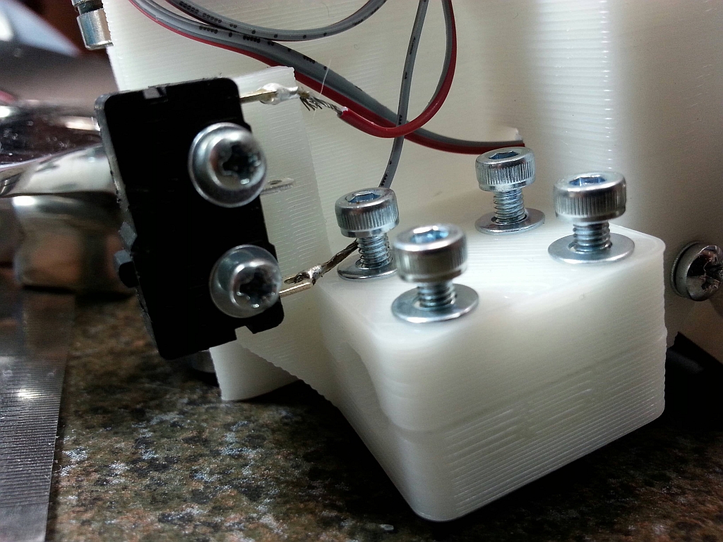
I ended up soldering the wires in from the side (90 degrees to the prong). This way they clear the screw heads entirely without putting any stress on the wire due to bending it. Hope this is good. I suspect the joints will be fine but I'm new to electrical soldering so it could be bad job number two - LOL! If so please let me know. I'd rather get this right now than troubleshoot something trivial later on.
Bye the way, where can I buy more of these same switches? Seems like a good idea to have some on hand.
Bye the way, where can I buy more of these same switches? Seems like a good idea to have some on hand.
|
Re: Soldering Limit Switch on X Motor Assembly October 02, 2013 02:33AM |
Registered: 10 years ago Posts: 301 |
Garry Bartsch Wrote:
-------------------------------------------------------
>
> Thank you. This is perfect. Wish I could have
> found a picture like this before I started. I will
> try to emulate this. I thought there should have
> been many examples like this on the web.
I try to document all of my projects as accurate as possible. You can find more of my pictures in my gallery.
Since yesterday evening I'm finished with the building. Today after work I'll do all the measurements. Tomorrow is calibrating day (it's a holiday in Germany) and I hope to print the Android Robot.
And there is the Raspberry Pi + PiCam lying around, already stuffed with OctoPi ... mounting it is another task on my list. I'll take photos whenever it's suitable and put them in my gallery.
MfG / Regards
Stefan
Blog / Gallery / Wiki / Mendel90 kit since Sep 2013 from Nophead / Original Prusa I3 MK3 since Feb 2018 /
OpenScad Workshop: Kursdateien
Octoprint Patron since April 2016
|
Re: Soldering Limit Switch on X Motor Assembly October 02, 2013 04:50PM |
Registered: 10 years ago Posts: 363 |
bastard Wrote:
-------------------------------------------------------
> I try to document all of my projects as accurate
> as possible. You can find more of my pictures in
> my
> [url=http://gallery.port23.de/v/bastard/3ddrucker/
> ]gallery[/url].
>
> Since yesterday evening I'm finished with the
> building. Today after work I'll do all the
> measurements. Tomorrow is calibrating day (it's a
> holiday in Germany) and I hope to print the
> Android Robot.
I enjoyed your pictures. Your's and other's blog pictures are helping me put my machine together. Looking forward to seeing your first prints.
Sorry, only registered users may post in this forum.