Additional ground connection between M90 and PC?
Posted by GerdH
|
Additional ground connection between M90 and PC? November 29, 2013 07:30AM |
Registered: 10 years ago Posts: 46 |
Recently I had several times problems with the USB communication between my M90 and the PC. If I'm switching on or off an inductive load (e. g. my soldering station) in the same room, it's very likely, that the communication is lost and the M90 stops printing.
I assume, that the problem is caused by power supply spikes which lead to short-time ground level differences between PC and M90, because both units for themselves are running without errors.
To reduce the ground level differences, I'm thinking about adding an additional, low resistance and low inductance ground connection between the PC and the M90 by a thick copper cable.
What are recommendable connection points at the Melzi board (PSU-GND connector where already the 12 black wires are connected?) and at the PC (the metall housing of one of the connectors, e. g. the VGA connector, or the Gnd of the power supply connector of a notebook?)?
Has somebody experiences with such grounding?
Cheers, Gerd
|
Re: Additional ground connection between M90 and PC? November 29, 2013 07:41AM |
Registered: 13 years ago Posts: 29 |
I have also experienced this interupt during prints. I have an old flourescent tube in the room and a desk lamp. Both cause the printer to stop if I turn them on while its printing. The desk lamp has a build in iron core transformer and the induced EM field is within the range of the USB lead. The flourescent tubes starter also seems to be emitting out some EMI too which I might need to take a look at. I'm actually considering an LED enclosure anyway so this won't be an issue for too much longer. But I might experiment with shielding the Menzi board with a homemade Faraday cage or buy in some of that conductive PLA plastic and build a shielding box for my circuits.
I agree that something has to be done to harden the M90 against basic interference, my house isn't really that "noisy" but it does cause failures
I agree that something has to be done to harden the M90 against basic interference, my house isn't really that "noisy" but it does cause failures
|
Re: Additional ground connection between M90 and PC? November 29, 2013 08:43AM |
Registered: 10 years ago Posts: 541 |
I am not sure that simply adding another ground between the PC and Melzi will help. This seems to be caused by an over-simplified design in respect of the Melzi electronics.
If you examine the circuit schematics of official Arduino boards you will see that there is an inductor to separate the USB connector shield and ground and transient suppressors and series resistors on the USB data lines. These all assist in improving the noise immunity of the data connection and, unfortunately, the Melzi electronics design does not feature any of these measures.
There is a risk that adding another ground connection between the PC and Mendel90 could introduce a ground loop and cause more problems than it solves. In an ideal grounded scenario all connections are made in a star pattern to a single grounding point. Communication between devices often defeats this unless appropriate measures are taken.
Ensuring you have a good connection between your Mendel90 PSU ground wires and the Melzi connector block goes a long way to reducing this problem. I have, coincidentally, placed my PC and Mendel90 on different wall sockets, in the same room, and have not experienced any disconnects during printing at all. I also do not switch other devices on or off during prints so that may help.
Of course, if you really do not want this to be an issue for unattended prints then print from SD card.
Regards,
Neil Darlow
Edited 1 time(s). Last edit at 11/29/2013 08:45AM by neildarlow.
I try to write with consideration for all nationalities. Please let me know if something is unclear.
Printing with Mendel90 from fedora 25 using Cura, FreeCAD, MeshLab, OpenSCAD, Skeinforge and Slic3r tools.
|
Re: Additional ground connection between M90 and PC? November 29, 2013 09:38AM |
Registered: 12 years ago Posts: 212 |
My £0.02 .... This topic has been discussed many times on the forum and the general consensus seems to be to avoid where possible, printing directly over USB. This has two main benefits, firstly it avoids the disconnect errors as all the important data traffic is onboard - the computer, if connected can be used to send the odd GCode command to speed things up / slow them down if needs be (M220) or to switch the fan on and off, again as needs be, (M206 /M207). Secondly, it makes the prints look better if the model demands a lot of complex tool paths, Yoda is often quoted in this context.
If USB printing is a 'must have' you can try using an opto isolator in between the computer and the MELZI. I bought one of these and wouldn't be without it although my work path now uses SD card printing almost exclusively.
Alan
If USB printing is a 'must have' you can try using an opto isolator in between the computer and the MELZI. I bought one of these and wouldn't be without it although my work path now uses SD card printing almost exclusively.
Alan
|
Re: Additional ground connection between M90 and PC? November 29, 2013 10:01AM |
Admin Registered: 17 years ago Posts: 7,879 |
Remove the auto reset jumper and print from the SD card. That is why it is provided as USB comms are not reliable between devices where both ends are grounded forming a loop. It also not fast enough for highly detailed models like yoda.
Inductors and extra ground connections will not help.Shielding the Melzi also won't help because it isn't that which is affected, just the USB comms in the wire experiencing different ground potentials at each end due to current induced in the loop by RF radiation. Reducing the area of the loop by having the PC next to the machine and running them both from the same mains connection helps. I have never had a problem with machines run like that. When plugged into different mains outlets I only have to switch a light off to get a USB disconnect.
[www.hydraraptor.blogspot.com]
|
Re: Additional ground connection between M90 and PC? December 08, 2013 11:35AM |
Registered: 10 years ago Posts: 46 |
Hello,
Thank you all for the suggestions.
My problem with printing directly from the SD card was, that I have my M90 inside of a heated chamber. So the access to the microSD card on the Melzi board is very inconvinient.
In between I added a card holder for an external SD card. The external standard SD card holder is connected via a short ribbon cable and an adapter board to the SPI interface located on JP17 of the Melzi board (the CS signal I had to fetch directly from a pin of the 4050 chip on the Melzi).
Actually I have to run the SD card with reduced SPI clock, because the 4050 chip on my adapter board is a standard CMOS type. When I receive a high speed version, I hope that I can run it again with the original 8MHz clock.
Another option for an undisturbed connection to the notebook is probably a Bluetooth to serial adapter, described on [reprap.org]
|
Re: Additional ground connection between M90 and PC? December 08, 2013 08:33PM |
Registered: 11 years ago Posts: 88 |
Have you considered hooking the printer up to a Raspberry Pi running Octopi? You could put the Pi near the Melzi electronics and add a WIFI dongle if you don't want any copper forming loops at all. Wired Ethernet or not, you would then be able to control and monitor your Mendel90 over a web interface.
I've been munging with a similar arrangement today and it is pretty nice. The only issue I have is that OctoPrint's controls don't seem to understand that the Mendel90's Z-stop is up top rather than below. That and I haven't yet been able to get a Raspberry Pi camera to work under Octopi (but it works fine under Rasbian).
Edited 1 time(s). Last edit at 12/08/2013 08:33PM by Rural.
|
Re: Additional ground connection between M90 and PC? December 09, 2013 06:54AM |
Registered: 10 years ago Posts: 46 |
|
Re: Additional ground connection between M90 and PC? December 09, 2013 08:05AM |
Admin Registered: 17 years ago Posts: 7,879 |
@GerdH,
You can extend the SDCard connection with a cable that plugs into the SD socket and has another SD socket at the other end. I.e. no electronics needed. Also to avoid a direct connection to CS you can just use another pin on the expansion header and change the pin definition. This is what the Panalolu2 does.
I am not sure if there is an easier way but I am sure you could connect with putty and then run avrdude from the command line to upload firmware. You can probably connect with VNC and use the arduino IDE as well.
@Rural,
You don't need to use Wifi to break the earth loop. Ethernet cables are isolated by transformers at each end so don't cause ground loops.
Not sure what you mean about the Octoprint not knowing about the Z limit at the top. Why does it need to know? It all seems to work for me. I.e. Z home takes it to the top and the up and down buttons work the right way.
[www.hydraraptor.blogspot.com]
|
Re: Additional ground connection between M90 and PC? December 13, 2013 05:28AM |
Registered: 10 years ago Posts: 46 |
The µSD card dummies with an attached ribbon cable to an external SD card holder are very difficult to obtain.
I have now replaced the standard CD4050 in my DYO SD card extension with a high speed 74HC4050 and the external SD card now works also with 8MHz SPI speed.
To redefine the CS pin for the SD card is a good idea (seems that I'm still thinking to much in hardware and not in software ...)
Also realized the proposal of Rural with the Raspberry, a Wifi stick and an USB Webcam. Anything worked without big problems. Only had to reprogram the USB interface of the Melzi to 115kBaud (250Kbaud is not a standard Baudrate of Raspberry, but I think there is also some work-around to enable this).
With the Z axis orientation I had no problems. Only the left and right buttons for jogging of the X axis are reverse, but the homing and software travel limitations are working correctly.
The central homing button of Octoprint doesn't include the Z axis homing (only XY). So first I accidently bumped the z axis in jog mode to one end stop and had to readjust the z axis :-(
|
Re: Additional ground connection between M90 and PC? December 13, 2013 08:04AM |
Admin Registered: 17 years ago Posts: 7,879 |
They are easy to find on eBay. Search for "Micro SD to Micro SD Card extension cable".
There are instructions to patch pyserial for 250KB on the octoprint github but I found it was already applied on the version of Raspbian that I downloaded and also on the OctoPi image I downloaded.
Buttons are logical directions (left negative, right positive), they won't correspond to physical directions as either X or Y will be wrong on a machine with a moving head X and moving table Y.
[www.hydraraptor.blogspot.com]
|
Re: Additional ground connection between M90 and PC? December 19, 2013 03:04AM |
Registered: 10 years ago Posts: 9 |
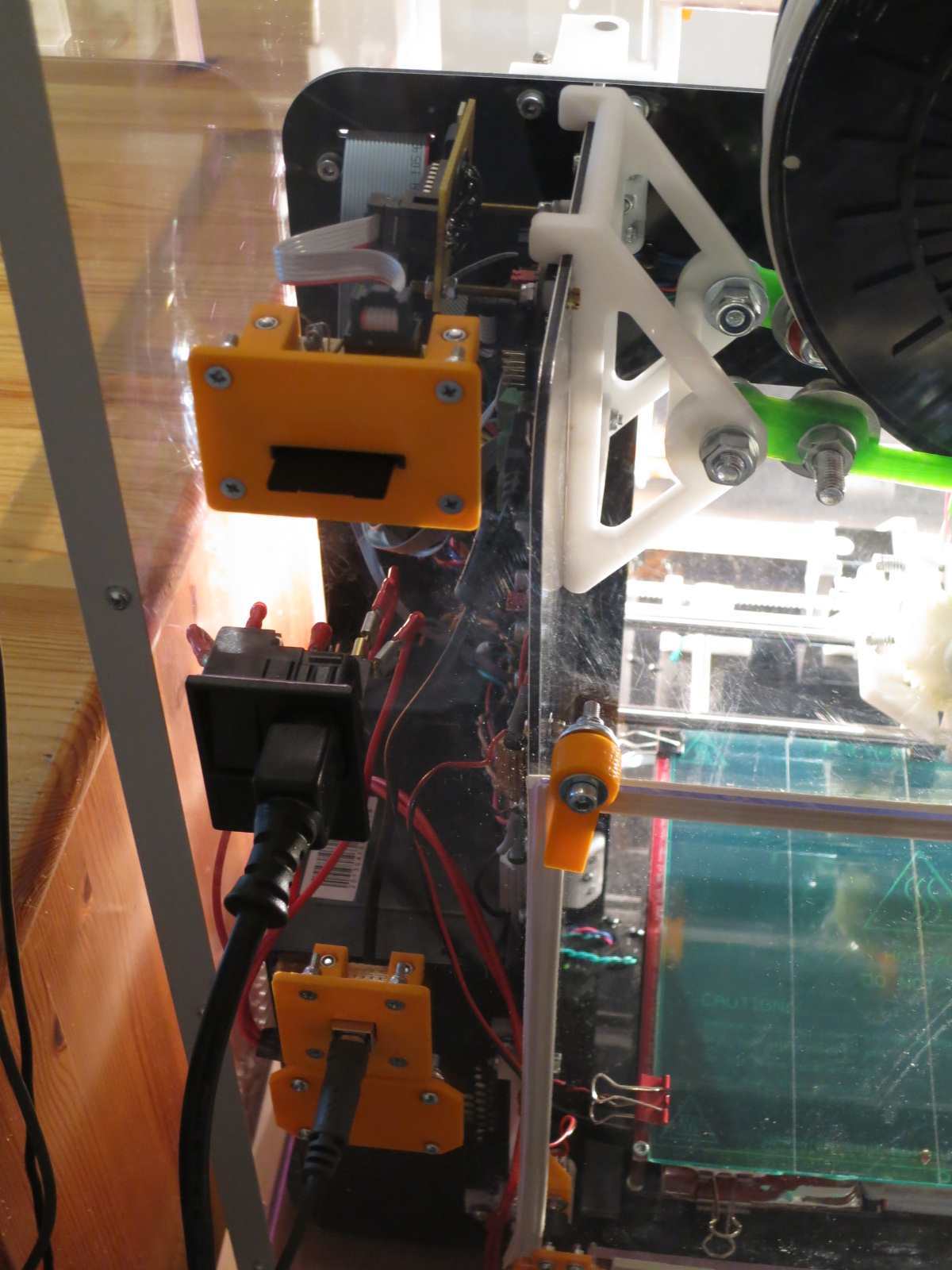
Hi guys! The USB interference problem has a very easy solution. You just have to solder the metal part of the mini USB port of the Melzi board to ground and add a resistor (1k-10k) between ground and +5V from the USB.
We are producing and selling Melzis in emakershop and have recently implemented this solution.
Here is a picture:
My eMAKERshop items: [www.emakershop.com]
We are producing and selling Melzis in emakershop and have recently implemented this solution.
Here is a picture:

My eMAKERshop items: [www.emakershop.com]
|
Re: Additional ground connection between M90 and PC? December 19, 2013 06:02AM |
Admin Registered: 17 years ago Posts: 7,879 |
|
Re: Additional ground connection between M90 and PC? December 19, 2013 06:43AM |
Registered: 10 years ago Posts: 9 |
When the jumper is connected so that the Atmega is powered by 12v input via the 7805 stabilizer, the PCB track that routes from the jumper to the Mini USB acts as an "antenna" so the interference "goes back" to the PC. This resistor "removes" the interference by "slightly" grounding it.
It is tested and works for hours in a room full of fluorescent lamps and other inductive consumers.
Edited 1 time(s). Last edit at 12/19/2013 06:44AM by mirox3m.
My eMAKERshop items: [www.emakershop.com]
It is tested and works for hours in a room full of fluorescent lamps and other inductive consumers.
Edited 1 time(s). Last edit at 12/19/2013 06:44AM by mirox3m.
My eMAKERshop items: [www.emakershop.com]
|
Re: Additional ground connection between M90 and PC? January 06, 2014 06:07AM |
Registered: 10 years ago Posts: 9 |
I actually tested one board without the resistor, just grounded USB metal shield and it also works nice.
Does anyone know what is the reason for the USB shield not to be grounded?
My eMAKERshop items: [www.emakershop.com]
Does anyone know what is the reason for the USB shield not to be grounded?
My eMAKERshop items: [www.emakershop.com]
|
Re: Additional ground connection between M90 and PC? January 06, 2014 09:04AM |
Admin Registered: 17 years ago Posts: 7,879 |
You would have to ask Joe Mosfet who designed it but in general the shield is not supposed to be connected directly to ground. If it was it would make the ground wire redundant. It would normally be connected to metal chassis or casing of your system for EMC reasons and that would be tied to ground with a resistor and a capacitor in parallel, see fig 7 here: [uk.farnell.com].
[www.hydraraptor.blogspot.com]
[www.hydraraptor.blogspot.com]
Sorry, only registered users may post in this forum.