Calibrating proper part size
Posted by Razorconcepts
|
Calibrating proper part size July 15, 2014 09:31PM |
Registered: 10 years ago Posts: 9 |
So I've been trying to calibrate my Mendel90 to print properly sized parts. Maybe some of you out there who have gone through this process with their Mendel90 and Skeinforge can chime in what they've learned.
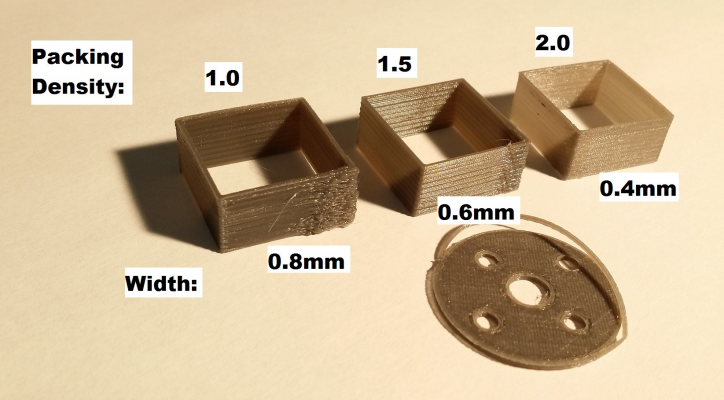
My main issue is that "inner dimensions", like holes, come out too small. I've followed this thin wall test, but that didn't seem to solve the problem - the settings for printing the thin wall resulted in the lines being too thin for anything else. Results below:
I have a feeling simply changing the packing density is not the proper solution to getting properly calibrated parts.
Now I've been trying to follow Nophead's guides on getting the right dimensions. Mainly, the first blog post here on the right equations for flow rate, and the recent post here further explaining it.
OK, on to testing. The baseline is the stock PLA0.2 profile from the settings on github. The main features are:
0.2mm layer height, 2.5 edge width over height, 2.25 infill width over thickness, 50 feed rate, 50 flow rate
(I have changed the diameter to 3.0mm to reflect my filament, as well as the temperature for this filament, and adjusted the E-steps-per-mm in the marlin firmware accordingly)
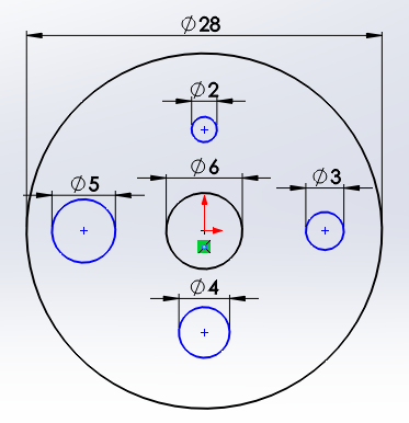
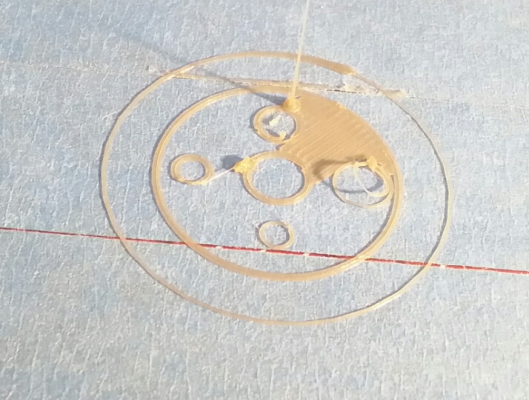
I created a small part with varying sized holes to test:
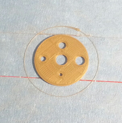
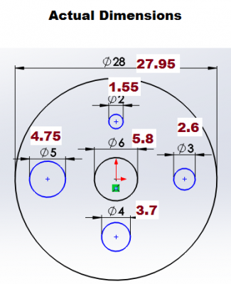
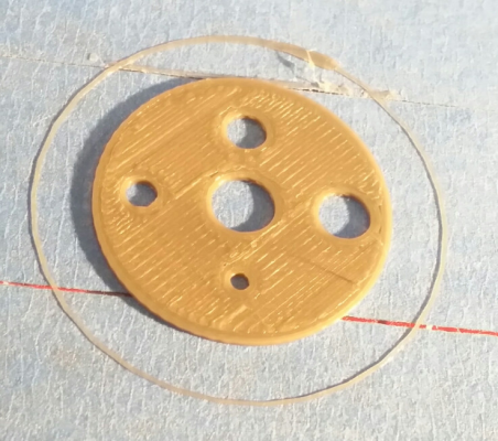
Here are my baseline results. It printed well enough, except as expected, the holes are too small
So, from the latest blog post, a W/H ratio of about 2.5 means a 0.92 multiplier on the flow rate. I changed the flow rate from 50 to 46. However, the filament did not stick to the bed, and I cancelled the print. Earlier, with the high flow rate, I think the filament was pressed down harder by the nozzle, so it stuck properly. Now with a lower flow rate, it doesn't stick as well.
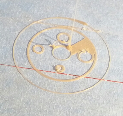
Not sticking could have been an issue with my temperature, since I am using a cheap filament that requires a higher temperature than the nice faberdashery sample. I raised the temp from 195 to 205, and here are the results. It seems to stick better now, but the lines are too thin - I can just peel the outer circles from the inner circles. Also, the filament seemed to be clumping up a bit.
It's possible I lowered the flow rate just slightly too much, so I increased the flow rate from 46 to 47, and here are my results.
The holes are slightly larger now, but not quite where I want them to be. The 6mm center hole is now around 5.9 millimeters in diameter, as opposed to the original at 5.8 millimeters.
Now, what should my next steps be? Going from 50 flow rate to 47 did help with the issue, but if I go any lower, the filament doesnt stick well to itself and the bed. Do I increase the temperature? Do I slow down the feedrate? Should I play with the W/H ratio? It seems like there are so many options. It also puzzles me that the first blog post Nophead made mentions an ideal 1.5 W/H ratio, as well as this older Skeinforge/Makerbot guide mentions it should be from 1.5 to 2.0. However, the stock 0.2mm PLA profile has it set to 2.5. Could the high W/H ratio contribute to larger extruded width, so my holes are too small?
|
Re: Calibrating proper part size July 16, 2014 03:30AM |
Registered: 11 years ago Posts: 369 |
|
Re: Calibrating proper part size July 16, 2014 04:49AM |
Admin Registered: 17 years ago Posts: 7,879 |
Yes, don't attempt to calibrate the machine with circles. Calibrate it so rectangles and rectangular holes are correct.
[www.hydraraptor.blogspot.com]
[www.hydraraptor.blogspot.com]
|
Re: Calibrating proper part size July 16, 2014 12:51PM |
Admin Registered: 17 years ago Posts: 7,879 |
To get circles the correct size you either need to use poly holes or a slicer that can compensate. There is a stretch module in Skeinforge but I have never tried it.
To minimise the error use PLA with thin layers, filament width close to nozzle width and higher temperatures to reduce the viscosity.
[www.hydraraptor.blogspot.com]
To minimise the error use PLA with thin layers, filament width close to nozzle width and higher temperatures to reduce the viscosity.
[www.hydraraptor.blogspot.com]
|
Re: Calibrating proper part size July 16, 2014 08:20PM |
Registered: 10 years ago Posts: 9 |
Thanks for the help. Could you clarify how to properly calibrate "filament width close to nozzle width"? Right now, I'm assuming filament width was "Carve/Edge Width over Height" times layer height. Since I am printing with a layer height of 0.2mm, I should be using an Edge Width over Height ratio of 2.0, to get a filament width of 0.4mm, the same as the nozzle size?
I've continued with the thin wall calibration. This time I made my own thin wall just in case, 20x20x5 cube, with 0.4mm thick walls. All of these were done with 47 flow rate, 50 feed rate:
From left to right:
1. I started with the base settings as a sanity check
2. Reducing the W/H to 2.0 helped significantly
3. Further reducing the W/H to 1.5 did not help
4. I went back to a W/H of 2.0, but increased the packing density
5. Further increased the packing density, and got close to the desired 0.4mm thickness. However, it had poor bed adhesion.
I tried to print another part using the #5 settings, however the filament would not stick to the bed.
Also a recurring problem is excessive globbing at the corner where it retracts, raises the Z axis, and extrudes again. For some reason this only happens on the thin wall parts, anything else I print seems to look good. I have a feeling this is a separate issue from the width calibration, since it's present in every thin wall test.
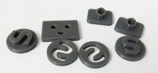
I'm just so confused why it's so drastically wrong from the beginning. In most thin wall calibration guides, usually if it's off, its off by like 0.2mm. Under my baseline settings, it's off massively: a 0.4mm line is printing 0.9mm wide. However, it still prints other items besides the thin wall with acceptable quality:
|
Re: Calibrating proper part size July 17, 2014 05:22AM |
Admin Registered: 17 years ago Posts: 7,879 |
Yes 0.2mm layers with W/H = 2 would give 0.4mm wide filament the same as the nozzle diameter, but you probably want it a bit wider at that height to avoid excessive stretching. For accurate round holes without any other form of compensation I think you would need even thinner layers.
It shouldn't be necessary to print thin walls and measure them. I only did that once many years ago. After establishing the formula I just use maths as detailed in the manual and measure the filament diameter and calibrate the E steps per mm. That only works with Skeinforge as other slicers have erroneous maths in them.
[www.hydraraptor.blogspot.com]
|
Re: Calibrating proper part size November 26, 2014 03:55PM |
Registered: 11 years ago Posts: 143 |
I just make the holes bigger in Openscad on an individual basis and measure the actual result and make adjustments until I get them right. This has provided me with an intuitive knowledge of how much bigger to adjust various holes to make them work out ,and I'm usually bang on. For instance, a 5mm hole for my machine needs to be about 5.35mm in Openscad. A 22mm hole needs to be about 23.17mm. Entering those values creates repeatable holes of exactly 5mm and 22mm. I use REM notes in my code to remind me of the true intended diameter, should I ever need to send them out to be printed or wish to share them. Thats never been the case because my designs are pretty much parts that I need and nobody else would want and I'd never be polluting Thingy verse with them. I think that I've not created any part with higher that 5 different sizes of holes, so that is not much work to figure out the compensation amount.
I have my machine set up to reliably print most objects accurately other than inside circles, and making the adjustments in Openscad, using intuition which is usually very accurate because of experience with my machine, is pretty much the same thing as having the slicer compensate. If this problem is ever truly solved at that level, I'll switch to a slice solution, but for now I just want my parts now and I want them to fit.
I don't like the idea of messing with flow rates and the like just to print the odd inside circle that needs to be accurate because that throws the normal calibrations off. As most of us know, tweaking our printers is a tiedeous task and once we get it producing decent prints, who wants to mess with that?
Edited 1 time(s). Last edit at 11/26/2014 03:57PM by Tekwizard.
Sorry, only registered users may post in this forum.
