Heater switching transients
Posted by Radian
|
Heater switching transients January 04, 2014 01:07PM |
Registered: 10 years ago Posts: 300 |
There are already several threads discussing issues with the power supply and they frequently include discussion about the heater switching transients. To avoid too much fragmentation it seems appropriate to isolate this particular topic in its own thread. Power supply problems, Power supply regulation, etc. can remain the main topic in those threads. My other topic regaring the quality of the 3.3V supply might be better, for example, if it focussed on the on-board 5V/3.3V regulators and USB powering issues however it includes plenty of discussion about heater switching transients. I hope we can continue with that issue here.
In summary, the two power MOSFETs switching current to the Bed and Extruder heaters both switch-off abruptly causing a rapid rise in voltage in the leg of the heater circuit being switched. This back-EMF, due to the rapid collapse of the magnetic field in the inductance of the heater element, produces a relatively high voltage (~45V) transient that appears at the Transistor's Drain terminal and is present in long runs of the heater wiring - providing plenty of scope for inductive and capacitive coupling into any sensitive nodes in the rest of the microcontroller electronics.
These transients are suspected of causing intermittent software crashes and while the actual point(s) of injection have yet to be identified, the fact that at least one Ormorod (mine) has gone from crashing somewhen during most attempts at printing to being wholly reliable after suppressing the transients strongly suggests that this is indeed the issue.
Several people have engineered their own different solutions and we've been discussing the relative merits of each one. All require a degree of modification to the original hardware generally adding components to suppress the high voltage spiking. So far we have looked at:
1) Slowing the turn-off of the power mosfet by using a resistor in series with the Gate and the Gate's intrinsic capacitance (dc42)
2) Providing a Transistor bypass path from Drain to Source using a capacitor (me)
3) Providing a free-wheeling path for the back-EMF via a Diode (DennisCowdery)
I think this just about sums it up, but many other people have contributed ideas along the way. I hope we can get heads together again in this thread.
RS Components Reprap Ormerod No. 481
|
Re: Heater switching transients January 04, 2014 01:26PM |
Registered: 10 years ago Posts: 14,672 |
Radian, thanks for separating this topic out, it needed doing. My main comment on that is that there are actually two potential problems caused by the rapid mosfet turn-off:
1. Back emf as you describe, possibly leading to interference with other signals on or reaching the Duet board, by capacitance, induction, or radiation.
2. A spike on the +12V line due to the sudden reduction in current draw and absence of local decoupling, leading to more direct interference with everything that is powered from +12V.
I'm not convinced that (1) is a problem, although it may well be, and the radiation may interfere with radio and even TV transmissions etc. I'm more certain that (2) is a problem. A solution that addresses both is preferable. Of the three solutions you list, the first two address both potential problems, whereas the third by itself only addresses the first. Dennis added a gate resistor as well as a flyback diode.
A fourth solution is to add a local decoupling capacitor or capacitors, in particular between bed heater +ve and supply -ve. This addresses (2) but not (1).
Large delta printer [miscsolutions.wordpress.com], E3D tool changer, Robotdigg SCARA printer, Crane Quad and Ormerod
Disclosure: I design Duet electronics and work on RepRapFirmware, [duet3d.com].
|
Re: Heater switching transients January 04, 2014 05:03PM |
Registered: 10 years ago Posts: 300 |
Hi dc, I didn't know that Dennis had also slugged the gate. Without that additional tweak the current drawn from the 12V would drop 10Amps in a few tens of nS rather than uS which is somethig I've been trying to avoid imposing on the "less than ideal" PSU we're working with.
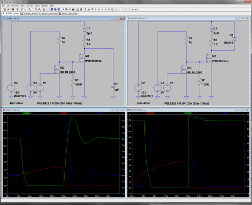
I ran a pair of sims in LTspice to illustrate the difference between the capacitor snubber and the freewheeling diode (green=Drain voltage, red=Gate voltage, blue=Heater current).
MOSFET_DIODE.asc
MOSFET_CAP.asc
The nice roundy edges are why I prefer the capacitor (between Drain and Source) over the diode (across the Heater) . Also, by soldering the cap across the tab and leg of the MOSFET, they act like a single component on the PCB - introducing no new current paths. I think we agree that adding a Gate resistor isn't an easy mod, adding a diode is easy but not if it also requires the Gate resistor.
However, I bet the diode on its own becomes the standard (it's what everyone seems to do) and, in conjunction with local 12V decoupling, probably achieves the same practical goal.
RS Components Reprap Ormerod No. 481
|
Re: Heater switching transients January 04, 2014 05:17PM |
Registered: 10 years ago Posts: 14,672 |
Can you run a simulation with just the gate resistor too? Preferably with 100 ohms (which is what I used) and also with 200 ohms.
PS - it would also be good to get the mosfet drain current from the simulation. I estimate that the capacitor discharge current is about 6A peak, using 1uF.
Edited 2 time(s). Last edit at 01/04/2014 05:23PM by dc42.
Large delta printer [miscsolutions.wordpress.com], E3D tool changer, Robotdigg SCARA printer, Crane Quad and Ormerod
Disclosure: I design Duet electronics and work on RepRapFirmware, [duet3d.com].
|
Re: Heater switching transients January 04, 2014 05:51PM |
Registered: 10 years ago Posts: 300 |
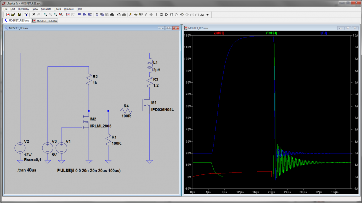
100R Gate:
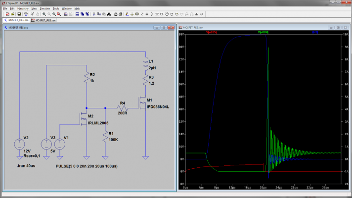
200R Gate:
Not what you were expecting? Avalanching doesn't appear to be being modelled. Not sure why not. I thought it was.
BTW LTspice is a freebie from Linear Technologies
1uF Capacitor between Drain & Source showing Drain current in blue:
Note that the peak current due to the relatively slow (2uS) switch-on is virtually the same as the steady Heater current (by design ) This is why it doesn't bother me one bit!
RS Components Reprap Ormerod No. 481
200R Gate:
Not what you were expecting? Avalanching doesn't appear to be being modelled. Not sure why not. I thought it was.
BTW LTspice is a freebie from Linear Technologies

1uF Capacitor between Drain & Source showing Drain current in blue:
Note that the peak current due to the relatively slow (2uS) switch-on is virtually the same as the steady Heater current (by design
 ) This is why it doesn't bother me one bit!
RS Components Reprap Ormerod No. 481
|
Re: Heater switching transients January 04, 2014 06:10PM |
Registered: 10 years ago Posts: 14,672 |
Radian, thanks for doing those. They are interesting, but the one with 100 ohm gate resistor is very different from the trace I captured here (4th photo down). Even though LTspice isn't modelling avalanching, the ringing that I observe is much more heavily damped than in your simulation. Some possible contributions to the difference are:
- From the first of my traces, I calculate the inductance of the bed circuit in my Ormerod to be closer to 1uH than 2.2uH
- You haven't modelled stray capacitance in the bed heater circuit. Also there is the added capacitance of my x10 probe (I might try adding a second probe to see how much difference it makes)
- How accurate is the LTspice model of the power mosfet? In particular, the effective gate-drain capacitance and the output capacitance.
Edited 2 time(s). Last edit at 01/04/2014 06:12PM by dc42.
Large delta printer [miscsolutions.wordpress.com], E3D tool changer, Robotdigg SCARA printer, Crane Quad and Ormerod
Disclosure: I design Duet electronics and work on RepRapFirmware, [duet3d.com].
|
Re: Heater switching transients January 05, 2014 05:08AM |
Registered: 10 years ago Posts: 300 |
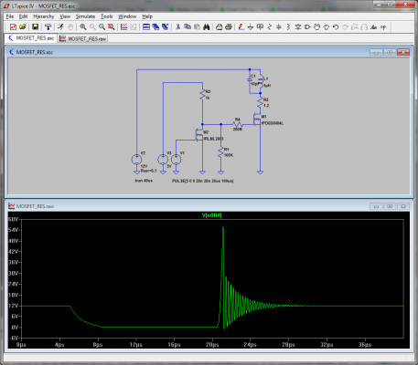
Of course dc42, you're right - with an unrealistic parasitic capacitance of Zero the sim really struggles with the "Gate resistor only" model. I only have to put on10pF to get a sensible response:
Increasing Cparasitic lengthens the time spent ringing, so by comparing with the real scope traces 10pF seems to be in the right ball-park. It has no discernable affect on the flyback diode/bypass capacitor models. I notice that the reprap wiki article Basics about switching loads with MOSFETs doesn't appear to include any parallel C either (although it doesn't necessarily appear on the schematic).
Of course we could finesse this kind of modelling until the cows come home - and LTspice allows the effects of the parasitics to be more acuratley modelled when they're entered as parameters for each component - but I'm satisfied that we're seeing enough to help us understand the differences in approach to damping the switching transients.
As for the value for inductance, I've also lumped-in 1uH for the ribbon cable which is about right I think. And LTspice is usually bang-on with the parasitics in the supplied component models. If you're not already using it I highly recommend it as I find it very useful and intuitive (not to mention it being free!).
Edited 1 time(s). Last edit at 01/05/2014 05:12AM by Radian.
RS Components Reprap Ormerod No. 481
|
Re: Heater switching transients January 05, 2014 08:47AM |
Registered: 12 years ago Posts: 1,236 |
If you use the gate resistor you also need to have the flyback diode to be effective I think.
What is Open Source?
What is Open Source Hardware?
Open Source in a nutshell: the Four Freedoms
CC BY-NC is not an Open Source license
What is Open Source?
What is Open Source Hardware?
Open Source in a nutshell: the Four Freedoms
CC BY-NC is not an Open Source license
|
Re: Heater switching transients January 05, 2014 11:48AM |
Registered: 10 years ago Posts: 14,672 |
Radian, the damping factor is still much greater in my scope trace than in your simulation. I think the ringing frequency is similar, although it's a it hard to tell the frequency on your simulation trace because of the horizontal scale. So I think the inductance of my bed + cable is much less than in your model, and the capacitance much greater. I don't think the ribbon cable has anything like 1uH of inductance, but I think it has a lot more than 10pf capacitance, probably several hundred pf.
Large delta printer [miscsolutions.wordpress.com], E3D tool changer, Robotdigg SCARA printer, Crane Quad and Ormerod
Disclosure: I design Duet electronics and work on RepRapFirmware, [duet3d.com].
Large delta printer [miscsolutions.wordpress.com], E3D tool changer, Robotdigg SCARA printer, Crane Quad and Ormerod
Disclosure: I design Duet electronics and work on RepRapFirmware, [duet3d.com].
Sorry, only registered users may post in this forum.


