How to calibrate the Ormerod.
Posted by Zonzo
|
How to calibrate the Ormerod. March 31, 2014 10:40AM |
Registered: 10 years ago Posts: 73 |
Hi everybody,
I need your help!!! I'm unable to have progress... so step by step, what I need to do??
Actually I've assembled my printer run the ormaxys.g create the setbed file (as show at the end) and printed a few pieces to improve the ormerod (y axys belt tensioner - z axys new nut - airduct), but overall I am not satisfied with the result of printing.
then I want to start over, what should I do?
I have also some doubts about the correctness of my files, sometimes I have problems with setbed and my prints start with Z too high until I reset bedplane and ortho compensation and do again the home & setbed.
I'm running with 57t firmware from DC42 (thanks again)
here my configuration:
Setbed
Config
Edited 1 time(s). Last edit at 03/31/2014 10:41AM by Zonzo.
I need your help!!! I'm unable to have progress... so step by step, what I need to do??
Actually I've assembled my printer run the ormaxys.g create the setbed file (as show at the end) and printed a few pieces to improve the ormerod (y axys belt tensioner - z axys new nut - airduct), but overall I am not satisfied with the result of printing.
then I want to start over, what should I do?
I have also some doubts about the correctness of my files, sometimes I have problems with setbed and my prints start with Z too high until I reset bedplane and ortho compensation and do again the home & setbed.
I'm running with 57t firmware from DC42 (thanks again)
here my configuration:
Setbed
G30 P0 X65 Y10 Z0.0
G30 P1 X65 Y180 Z0.4
G30 P2 X180 Y180 Z-0.4
G30 P3 X180 Y10 Z-1.4 S
M556 S74.1 X0.05 Y0.125 Z0.5
Config
; RepRapPro Ormerod
; Standard configuration G Codes
M111 S1; Debug on
M550 POrmerod; Set the machine's name
M551 Preprap; Set the password
M552 Pxx.xx.xx.xx; Set the IP address
M553 P255.255.255.0; Set netmask
M554 Pxx.xx.xx.xx; Set the gateway
M555 P2; Emulate Marlin USB output
M92 E431.4; Set extruder steps/mm
G21 ; Work in mm
G90 ; Absolute positioning
M83 ; Extrusions relative
M558 P1 ; Turn Z Probe on
G31 Z1 P545 ; Set Z probe height and threshold
M906 X800 Y800 Z800 E800 ; Motor currents (mA)
T0 ; Select extruder 0
Edited 1 time(s). Last edit at 03/31/2014 10:41AM by Zonzo.
|
Re: How to calibrate the Ormerod. March 31, 2014 11:09AM |
Registered: 10 years ago Posts: 14,672 |
Hi Zonzo,
In what way are you not satisfied with the result of printing - what is going wrong? What slic3r settings are you using, assuming you are using slic3r to prepare your own gcode files?
I have a few small suggestions:
1. Check whether your G30 setbed parameters are still correct, preferably when the bed is at operating temperature. If you find the z-height at all unstable, then reinforce the MDF bed support, or replace it with aluminium (there are a few threads about this).
2. Remove the M111 S1 command from config.g. It slows down direct printing, and it's only needed when debugging.
3. Increase the Y motor current in the M906 command to 1000mA.
4. Upgrade to 057y-dc42 firmware
Large delta printer [miscsolutions.wordpress.com], E3D tool changer, Robotdigg SCARA printer, Crane Quad and Ormerod
Disclosure: I design Duet electronics and work on RepRapFirmware, [duet3d.com].
|
Re: How to calibrate the Ormerod. March 31, 2014 12:24PM |
Registered: 10 years ago Posts: 73 |
Quote
dc42
1. Check whether your G30 setbed parameters are still correct, preferably when the bed is at operating temperature. If you find the z-height at all unstable, then reinforce the MDF bed support, or replace it with aluminium (there are a few threads about this).
2. Remove the M111 S1 command from config.g. It slows down direct printing, and it's only needed when debugging.
3. Increase the Y motor current in the M906 command to 1000mA.
4. Upgrade to 057y-dc42 firmware
Hi,
look at the enclose immage, the print have a lot of imperfection and in this particular case (I assume this is a Slic3r fault) some perimeters are missing or moved from their position...

One of my first Ormerod Mod was the reinforce of the MDF bed with a square of aluminium and it was a good mod, the z-height seems correct all time (i'll ceck it everytime with some office paper)
Ok for the Debug mode, usually i send the S0 command when i conect the printer to the usb, but usually i connect only with the web interface.
Y motor current to 1000mA, ok I'll do it immediatly!!
057y-dc42 already downloaded, ready to install it this evening

|
Re: How to calibrate the Ormerod. March 31, 2014 12:39PM |
Registered: 10 years ago Posts: 14,672 |
A few more suggestions:
1. I think you are probably extruding at too high a temperature. I use 195C first layer and 190C for the rest.
2. Have you increased retraction in the slic3r settings to 4mm yet?
3. Check your X and Y belt tensions. The X belt tension can be adjusted by moving the x-motor screws in the slots, then tightening them. For the Y belt, I recommend Matt's y-belt fasteners at [github.com] and then use my spacers at [github.com] to adjust the tension.
4. That inlet duct is a tricky thing to print because the side walls are very thin and fragile and the blades are very thin. I have a modified version of his design at [github.com]. It's designed to screw on instead of clip on, and it is thinner so that I didn't have to relocate the Duet enclosure.
Large delta printer [miscsolutions.wordpress.com], E3D tool changer, Robotdigg SCARA printer, Crane Quad and Ormerod
Disclosure: I design Duet electronics and work on RepRapFirmware, [duet3d.com].
|
Re: How to calibrate the Ormerod. March 31, 2014 06:04PM |
Registered: 10 years ago Posts: 73 |
Thanks for your help, really appreciated!!!Quote
dc42
A few more suggestions:
I usually extrude at 185° for all the layer (too low? it look easy to extrude...)Quote
dc42
1. I think you are probably extruding at too high a temperature. I use 195C first layer and 190C for the rest.
The retraction was one of my first change to the slic3r setting (my first 3 print was full of blob and filament), i found some suggestion on the forum and i set it exactly to 4mm, recently I've reduce the retraction speed to 30 due to some noise from the E motor (probably nothing but I need to try).Quote
dc42
2. Have you increased retraction in the slic3r settings to 4mm yet?
I've also already print and installed the Iamburny belt fasteners (and his Web interface... THANKS!!!) but not your spacers. I've install the fasteners without fix the screw, then put the belt inside and at the end I've finish to fix the screw so the belt now is good in tension. About the X belt I've try to fix the motor but I think that the shinny part of the x axis let the screw slip forward...Quote
dc42
3. Check your X and Y belt tensions. The X belt tension can be adjusted by moving the x-motor screws in the slots, then tightening them. For the Y belt, I recommend Matt's y-belt fasteners at [github.com] and then use my spacers at [github.com] to adjust the tension.
tomorrow i'll try to print your inlet duct (but I prefer the clip version...)Quote
dc42
4. That inlet duct is a tricky thing to print because the side walls are very thin and fragile and the blades are very thin. I have a modified version of his design at [github.com]. It's designed to screw on instead of clip on, and it is thinner so that I didn't have to relocate the Duet enclosure.
Also the Z axis rod is new, I've replace it with a stainless steel rod and a 10mm nut brass 2cm high (with thread 5mm) combined with the bearing fixed it seems a thousand times better solution than original but I'm not sure this is sufficient to prevent wobble (???) effect...
the problem is that I've read a lot and already try to fix my problem, but it is frustrating to see that poor results after 3 week of full immersion work
here enclosed my Slic3r setting file
|
Re: How to calibrate the Ormerod. March 31, 2014 08:35PM |
Registered: 10 years ago Posts: 859 |
Hi Zonzo, I think your extruder temp is higher than you think my friend.
Maybe you can measure it to find out. Sometimes the thermistors are not reading correctly.
Also with the Retraction set to 4mm, increase the speed...
I see you are using:-
retract_speed = 30
Increase this to 45...
I see you are trying to reduce BackWash from the Fan.... Try my Duct as it will work better.
Kim..
Please send me a PM if you have suggestions, or problems with Big Blue 360.
I won't see comments in threads, as I move around to much.
Working Link to Big Blue 360 Complete
|
Re: How to calibrate the Ormerod. April 01, 2014 02:13AM |
Registered: 10 years ago Posts: 73 |
Quote
KimBrown
Hi Zonzo, I think your extruder temp is higher than you think my friend.
Maybe you can measure it to find out. Sometimes the thermistors are not reading correctly.
Also with the Retraction set to 4mm, increase the speed...
I see you are using:-
retract_speed = 30
Increase this to 45...
I see you are trying to reduce BackWash from the Fan.... Try my Duct as it will work better.
Kim..
hi Kim I have reed with a lot of interest your previous post, so thanks for your interest!
How can I measure the temperature to ceck it is correct?
There any kind of test I can do to set the correct extruding temperature?
Yes, I've reduce the retraction speed due to some noise I hear from the E motor, probably due to the knurled part of the filament that scratch on the beginning of the PTE guide... anyway I set it back to 45.
|
Re: How to calibrate the Ormerod. April 01, 2014 02:54AM |
Registered: 10 years ago Posts: 1,230 |
Quote
Zonzo
How can I measure the temperature to ceck it is correct?
There any kind of test I can do to set the correct extruding temperature?..
You could do a compare between the bed and the nozzle temperature, not a perfect test but would give you a hint about something being way off
Set the bed temperature as high as it will go, lower the nozzle to the bed, let it sit for a moment as to let the air settle, then compare the reading of the bed temp to the nozzle temp in proterface
Erik
|
Re: How to calibrate the Ormerod. April 01, 2014 03:17AM |
Registered: 10 years ago Posts: 73 |
but to do that and have a correct reading I need to remove the thermoresistor from the hotend and put it directly in contact with the bed (preferibly with a piece of kapton to fix it to the bed surface... and also disconnect the fan) right?
Edited 1 time(s). Last edit at 04/01/2014 04:29AM by Zonzo.
Edited 1 time(s). Last edit at 04/01/2014 04:29AM by Zonzo.
|
Re: How to calibrate the Ormerod. April 01, 2014 04:02AM |
Registered: 10 years ago Posts: 73 |
I found a BIG mistake on my power connection: I have connected only the 24 pin connector of the ATX to the Ormerod Power Board, without conect the 4 pin connector... I have use this power configuration for all my print until today...
may have created problems?? maybe the engines did not have the correct power when both bed and hotend require power to reach temperature...

may have created problems?? maybe the engines did not have the correct power when both bed and hotend require power to reach temperature...
|
Re: How to calibrate the Ormerod. April 01, 2014 04:12AM |
Registered: 10 years ago Posts: 859 |
Hi Tim, I think Erik was meaning look at the temperatures when you first turn on the machine, to make sure they are nearly the same.
Kim
Please send me a PM if you have suggestions, or problems with Big Blue 360.
I won't see comments in threads, as I move around to much.
Working Link to Big Blue 360 Complete
Kim
Please send me a PM if you have suggestions, or problems with Big Blue 360.
I won't see comments in threads, as I move around to much.
Working Link to Big Blue 360 Complete
|
Re: How to calibrate the Ormerod. April 01, 2014 04:13AM |
Registered: 10 years ago Posts: 73 |
|
Re: How to calibrate the Ormerod. April 01, 2014 04:31AM |
Registered: 10 years ago Posts: 73 |
Ok, I have just generate a gcode for the kim's fan duct with the setting suggestion receved on this thread:
1-increase y motor to 1000mA
2-increase retraction speed
3-reduce hotend temperature (set to: 185° first layer and 180° other that should be like 190,8° and 185,8°... I hope...)
4-Update the firmware to 057y-dc42
5-increase x axis belt tension (y look ok at me)
6-also fix my power connection!
Any other suggestion are welcome!
|
Re: How to calibrate the Ormerod. April 01, 2014 04:51AM |
Registered: 10 years ago Posts: 73 |
|
Re: How to calibrate the Ormerod. April 01, 2014 06:30AM |
Registered: 10 years ago Posts: 859 |
Hi Zonzo, that's interesting. What size is the nut on your Z drive? I use the standard threaded bar, with a long nut to spread the load.
With the original, I found I was getting swarf from the original nut, and sometimes it tried to sieze up..... (Not good).
So I changed it for a nut that was 20-25mm long to spread the load, and give it a gentle oil with my WD40 pen about once every 3to4 weeks.
It's been good, with no noises,swarf, or siezing.... You should be able to use the Fan-Duct as it's not much wider than the Heatsink (about 2mm), and if you are using the original probe in it's original position then I can edit the Fan-Duct to remove the arm for the probe if that helps...
I don't think your in the UK, but here at MAPLIN then sell pocket Infra Red Pen thermometers for about £15. I intend to get one today.
I don't suppose they are wonderfully accurate, but I can soon boil the kettle up and see what temp it tells me the water is boiling at....lol
Sounds like a coffee time I think....
Let me know if editing the file would help you, and I'll do it today for you...
Kim
Please send me a PM if you have suggestions, or problems with Big Blue 360.
I won't see comments in threads, as I move around to much.
Working Link to Big Blue 360 Complete
|
Re: How to calibrate the Ormerod. April 01, 2014 08:00AM |
Registered: 10 years ago Posts: 73 |
Thanks Kim, but don't worry,
the problem about the Z nut is that I'm not a guru in 3d modelling so I've made a wrong size nut hole so it is bigger than necessary, if you want to help me, I need a nut base for a 10mm nut (i've made a 10mm brass nut with 5mm thread, the nut is 15mm high), because I'm not able to use the original stl file and modify it.
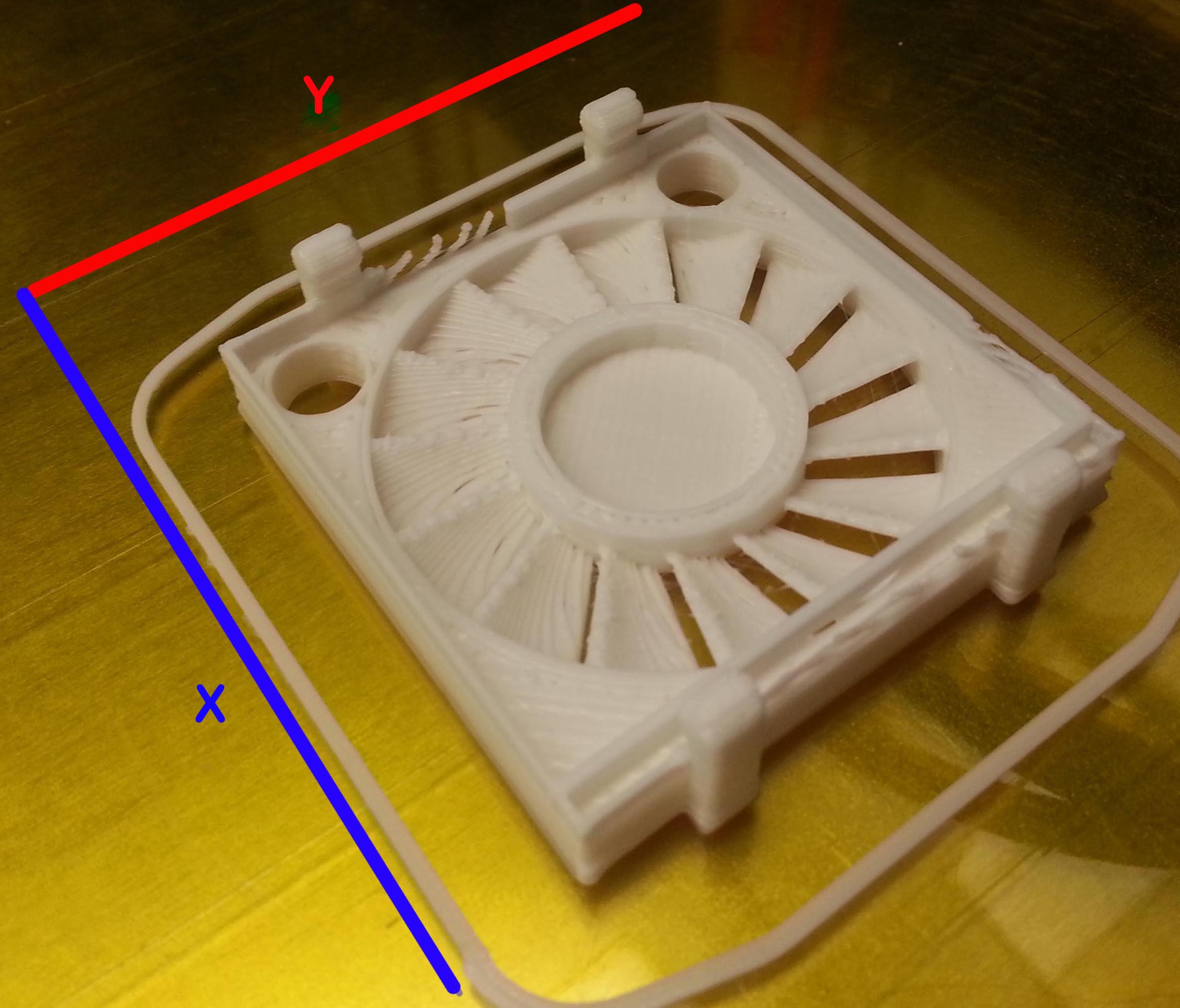
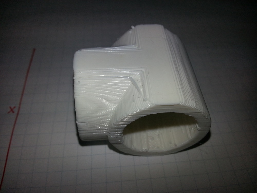
here enclosed the picture of the last print: dc42 fan duct... i see a lot of line in x and y axis, but actually I'm sure about the y belt is tight and also the x for me is ok.
I put also some picture of the nut I made and his seat that is too big for your duct.
the problem about the Z nut is that I'm not a guru in 3d modelling so I've made a wrong size nut hole so it is bigger than necessary, if you want to help me, I need a nut base for a 10mm nut (i've made a 10mm brass nut with 5mm thread, the nut is 15mm high), because I'm not able to use the original stl file and modify it.
here enclosed the picture of the last print: dc42 fan duct... i see a lot of line in x and y axis, but actually I'm sure about the y belt is tight and also the x for me is ok.
I put also some picture of the nut I made and his seat that is too big for your duct.
Attachments:
open | download - Nut.jpg (84.9 KB)
open | download - seat of the nut.jpg (92.4 KB)
open | download - seat of the nut 2.jpg (87.8 KB)
open | download - 20140401_125742.jpg (51.3 KB)
open | download - 20140401_125752.jpg (57.3 KB)
open | download - 20140401_125805.jpg (73.3 KB)
open | download - 20140401_130700.jpg (49.2 KB)
open | download - 20140401_130104.jpg (58.9 KB)
|
Re: How to calibrate the Ormerod. April 01, 2014 08:38AM |
Registered: 10 years ago Posts: 14,672 |
The screw holes should come out better if you change the slic3r settings to reduce the speed for small perimeters to 15mm/sec. I'm experimenting with reducing the X and Y axis accelerations, to see if this reduces the appearance of steps in the print.
Large delta printer [miscsolutions.wordpress.com], E3D tool changer, Robotdigg SCARA printer, Crane Quad and Ormerod
Disclosure: I design Duet electronics and work on RepRapFirmware, [duet3d.com].
Large delta printer [miscsolutions.wordpress.com], E3D tool changer, Robotdigg SCARA printer, Crane Quad and Ormerod
Disclosure: I design Duet electronics and work on RepRapFirmware, [duet3d.com].
|
Re: How to calibrate the Ormerod. April 01, 2014 09:11AM |
Registered: 10 years ago Posts: 73 |
Quote
dc42
The screw holes should come out better if you change the slic3r settings to reduce the speed for small perimeters to 15mm/sec. I'm experimenting with reducing the X and Y axis accelerations, to see if this reduces the appearance of steps in the print.
ok, thanks, small perimeter speed reduced to 15mm/s!
about the line on the x and y axis? do you think it is a belt tension problem?
can i print something to check that?
|
Re: How to calibrate the Ormerod. April 01, 2014 09:28AM |
Registered: 10 years ago Posts: 1,230 |
Quote
Zonzo
about the line on the x and y axis? do you think it is a belt tension problem?
can i print something to check that?
You could do the Single Wall Alignment Test and check your extrusion multiplier as well - two for the price of one!
[www.thingiverse.com]
Erik
|
Re: How to calibrate the Ormerod. April 01, 2014 09:35AM |
Registered: 10 years ago Posts: 2,472 |
Quote
KimBrown
... but here at MAPLIN then sell pocket Infra Red Pen thermometers for about £15. I intend to get one today.
I don't suppose they are wonderfully accurate, but I can soon boil the kettle up and see what temp it tells me the water is boiling at....lol
Sounds like a coffee time I think....
Kim
Most IR thermometers are of little use in measuring the hotend temperature. Firstly almost all will have a target diameter larger than the hotend (the small target thermometers are very expensive), and secondly aluminium has poor (low) emissivity and so requires a large correction factor to be applied that is unlikely to be accurate. It should be able to measure the bed temperature OK if you stick some black tape on the glass (IR thermometers won't measure the temperature of plain glass).
To measure the hotend temperature, I remove the filament and insert a standard wire type thermocouple probe down the Bowden tube till it bottoms in the nozzle.
Dave
(#106)
|
Re: How to calibrate the Ormerod. April 01, 2014 09:42AM |
Registered: 10 years ago Posts: 73 |
ok, thanks Erik!
the print is already started
I have some doubt about extrusion: the first time I do the test I use the 0,5mm tin wall test but I haven't understand how to check the extrusion multiplier... it give me a value too low so I decide to set it to 0.9 just to set something... now I have reset the value to default (1), tell me how to check that value after the print please!
Giuliano
|
Re: How to calibrate the Ormerod. April 01, 2014 10:08AM |
Registered: 10 years ago Posts: 2,472 |
Assuming your G file header shows a "perimeters extrusion width" of 0.5mm (view the G file as text), then after measuring the wall thickness of your single wall part, the extrusion multiplier should be set to 0.5 divided by your measured value. Mine came out as 0.8333 (my wall measured 0.6mm).
Dave
(#106)
Dave
(#106)
|
Re: How to calibrate the Ormerod. April 01, 2014 10:12AM |
Registered: 10 years ago Posts: 1,230 |
Quote
Zonzo
.. now I have reset the value to default (1), tell me how to check that value after the print please!
Measure the four wall thickness, take the average and compare it to the perimeters extrusion width noted in your Thin_wall_test.gcode file e.g.
--------------
; generated by Slic3r 1.0.0RC2 on 2014-03-26 at 17:36:03
; layer_height = 0.24
; perimeters = 2
; top_solid_layers = 4
; bottom_solid_layers = 3
; fill_density = 0.4
; perimeter_speed = 40
; infill_speed = 40
; travel_speed = 60
; nozzle_diameter = 0.5
; filament_diameter = 1.75
; extrusion_multiplier = 1.0
; perimeters extrusion width = 0.50mm
-----------
If you measure your average to e.g. 0.60mm, then your new extrusion multiplier should be 0.5 / 0.60 = 0.83

Erik
|
Re: How to calibrate the Ormerod. April 01, 2014 10:42AM |
Registered: 10 years ago Posts: 73 |
ok, I have stop the print after 25mm, the perimeter seems good, but in the corner there are some hole...
after a check I found that the wall thickness measure from 0,54 to 0.51mm (using a professional micrometer) so I think to set the extrusion multiplier to 0,50/0,52 = 0,96
so why when i print simple test wall the layer is perfectly on line and when i print other object they have some traslation effect?
and how to solve the for the small hole??? if i set the extruder multiplier to 0,96 the extruder will extrude less than now so the hole may be bigger, right??
Giuliano
|
Re: How to calibrate the Ormerod. April 01, 2014 03:51PM |
Registered: 10 years ago Posts: 1,230 |
Quote
Zonzo
so why when i print simple test wall the layer is perfectly on line and when i print other object they have some traslation effect?
Nothing comes to mind at the moment, sorry
Quote
..and how to solve the for the small hole??? if i set the extruder multiplier to 0,96 the extruder will extrude less than now so the hole may be bigger, right??
might as well be other things influencing the attachment of the filament at the starting point, could be 4mm extraction is too much for your setup?
You should be able to print it without any holes, my very same printed object is watertight
Erik
|
Re: How to calibrate the Ormerod. April 02, 2014 08:50AM |
Registered: 10 years ago Posts: 73 |
no way...
the Thin Wall stl give me good results, but when I try a real and complex print the quality isn't soo good.
last print give me a bad results look at the picture.
now, with the same setting of the thin wall test the print result with some areas where the filament is not completely melted, and again some sign of X and Z not perfectly alligned...
so I've change again the setting about the temperature and put first layer at 195 and other at 190 with bed at 65-60
reduce the travel speed from 60 to 50
reduce gap fill from 10 to 8 (to reduce the vibration of the x arm
print and install some Vibration Damper (not sure if it is a good idea...)
the picture are made with the old setting
Giuliano
|
Re: How to calibrate the Ormerod. April 02, 2014 11:14AM |
Registered: 10 years ago Posts: 2,472 |
Your part in the first photographs looks pretty good to me. Closing the top of a horizontal tube is always a problem that gets worse as the tube diameter increases. The problem being that the overhang at the top of a large tube gets to way more than 45 degrees so there is little or nothing to support the inside perimeter. The small holes in your thin wall test may have been caused by water or other contamination of your filament - the plastic filament absorbs water (humidity) from the air and causes small voids in the extrusion unless you store it in an airtight container with silica gel. On the last photograph I would guess that your hotend temperature needed to be a bit higher. The alignment problem could be caused by slightly loose X or Y belts, or the X arm moving. The X arm can be pulled by resistance on the filament - try hanging the extruder in the position closest to the Z support rather than in the middle of the X arm, and make sure the filament is unwinding easily from the reel.
Dave
(#106)
Dave
(#106)
Sorry, only registered users may post in this forum.