Instructions improvement suggestions
Posted by droftarts
|
Instructions improvement suggestions December 28, 2013 05:42AM |
Registered: 12 years ago Posts: 1,611 |
|
Re: Instructions improvement suggestions December 28, 2013 06:32AM |
Registered: 10 years ago Posts: 256 |
|
Re: Instructions improvement suggestions December 28, 2013 06:35AM |
Registered: 10 years ago Posts: 256 |
|
Re: Instructions improvement suggestions December 28, 2013 07:01AM |
Registered: 12 years ago Posts: 1,611 |
Quote
kwikius
In Electronics para 2
"The M4x16mm countersunk screw goes through the lug on the side, again with a spacer and T-nut on it."
Thanks, done!
Quote
kwikius
In Hot end assembly > Final assembly > List of components at start
I believe the 16 mm screws should be listed as countersunk not cap head
There are not enough M3x16mm countersunk screws supplied with the kit, so we specify the cap heads. Countersunks would be nicer, as the nozzle-mount has a taper for them, but it doesn't really matter. The cap head has a bigger hex, which makes it a bit easier to do up/undo. I've added a note under the picture; there is also a note later on, when mounting the hot end. I'll redo the pictures when I update the instructions.
Ian
RepRapPro tech support
Edited 2 time(s). Last edit at 12/28/2013 07:01AM by droftarts.
|
Re: Instructions improvement suggestions December 28, 2013 07:02AM |
Registered: 10 years ago Posts: 135 |
|
Re: Instructions improvement suggestions December 28, 2013 07:39AM |
Registered: 12 years ago Posts: 1,611 |
Quote
Rory166
When fitting the z-axis sprocket please move description of whch way up it goes to the start of the section not near the end. I fitted it then read it should be other way up! I apreciate you do say thoroughly read and understand whole thing before starting, but even so this would help.
Do you mean the z-gear on the z axis motor? I updated that ages ago! It is the first thing in the main section here: [www.reprappro.com]
Have just added the bit about aligning the flat, though.
Ian
RepRapPro tech support
|
Re: Instructions improvement suggestions December 28, 2013 08:41AM |
Registered: 10 years ago Posts: 14,672 |
In the final 3 photos on the heated bed assembly page, you have the board connectors at the front and the hole for the thermistor wires on the left. This means that the cutout in the cardboard for the connectors is off-centre. This in itself doesn't really matter because it still fits; however if you then line up the cutout in the heat spreader plate with the cutout in the cardboard, then the heat spreader plate shorts against one of the heated bed connections. So it would be better to show the thermistor fitted with the wires pointing towards the right (they will point to the left when the bed is turned the right way up).
Large delta printer [miscsolutions.wordpress.com], E3D tool changer, Robotdigg SCARA printer, Crane Quad and Ormerod
Disclosure: I design Duet electronics and work on RepRapFirmware, [duet3d.com].
Large delta printer [miscsolutions.wordpress.com], E3D tool changer, Robotdigg SCARA printer, Crane Quad and Ormerod
Disclosure: I design Duet electronics and work on RepRapFirmware, [duet3d.com].
|
Re: Instructions improvement suggestions December 28, 2013 08:49AM |
Registered: 10 years ago Posts: 14,672 |
In the Tools list:
- I suggest you recommend having ball-ended 2mm and 2.5mm hex drivers, because there are so many screws and it would take ages to assemble an Omerod using just allen keys
- Also useful is a spanner (5.5mm?) for the M3 nuts
- I bought the calipers, but never found out what I was supposed to use them for
- I also needed a 6mm drill to enlarge the hole in the z-nut trap, however that was before you changed the design of it.
Large delta printer [miscsolutions.wordpress.com], E3D tool changer, Robotdigg SCARA printer, Crane Quad and Ormerod
Disclosure: I design Duet electronics and work on RepRapFirmware, [duet3d.com].
|
Re: Instructions improvement suggestions December 28, 2013 08:54AM |
Registered: 10 years ago Posts: 22 |
Hi
You definitely need long allen keys , ball end preferred and ideally T bar ones , I struggled with short ones but I wouldn't let it beat me.
I would make it clear that the printing bed is the kapton side upwards. ( i assumed it was glass side up and it was only when i was not getting the IR Z readings in the 600's that i twigged it was the other way round )
The printed Z gear in my set did not have a defined flat so this took a while to sort out so a clear instruction on this and aligning the flat on the shaft would help.
I struggled making the tiny crimped end connections (thank god there were plenty spare in the kit )
Overall I think the instructions were brilliant. - If you lot could build one in 2 hours then fair play ! it took me 10.
The kit was so well put together , i enjoyed building it i feel like buying another kit .
Just can't wait for the 3 coloured print head !!!!!!1
H
Edited 2 time(s). Last edit at 12/28/2013 08:57AM by hughesie.
|
Re: Instructions improvement suggestions December 29, 2013 06:01PM |
Registered: 10 years ago Posts: 256 |
First... Glad to say I have progressed to commissioning 
In Commisioning section...
Re the para "IMPORTANT. Next press “Check Temp” and check that both the hot end and the heated bed are reporting a temperature that is around room temperature (it may be a couple of degrees out – the thermistors are designed for accuracy at their operating temperature). [...]."
For a long while I couldnt figure out where this was being reported in the GUI. I got no info from the text terminal. Should I wait there? ... Was it in the little textboxes in the line of Heat and Bed lanels... Unfortunately in my Pronterface GUI, some of the text boxes are way too short for the text.
Anyway eventually I figured out that the T:13.6 B:22.5 in the bottom right of the window was what I was looking for. Could probably clarify this in this part of docs!
Interestingly the T value switches exactly between the two values 13.6 and 9.8 (mainly 13.6 with the odd dip!) I hope this value isnt too far out?
(Actual temperature in the room is probably around 20-25 degrees C) I assume its the 100 K thermistor on the hotend, which doesnt have to be accurate at room temperature? (Just to be sure everything was hunky dory with the hardware I measured my resistance at the board. The Bed thermistor read around 10 k and the hotend around 100 k.
regards
Andy
Ormerod #318
www.zoomworks.org - Free and Open Source Stuff
|
Re: Instructions improvement suggestions December 30, 2013 11:17AM |
Registered: 11 years ago Posts: 103 |
may be an improvement, but may also be more of a question:
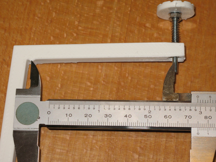
Orthogonal Axis Compensation
picture attached. Tip of screw or not should be a difference of ca. 0.3 so does not explain 75 to 78.
Orthogonal Axis Compensation
i measure closer to 75 and I think this distance should be defined by pully / belt so should not really have that big a difference. maybe I did not measure correctly?Quote
Finally, measure the distance between the tip of the projection near the angled corner and the center of the end of the screw. This should be 78mm
picture attached. Tip of screw or not should be a difference of ca. 0.3 so does not explain 75 to 78.
|
Re: Instructions improvement suggestions December 30, 2013 11:22AM |
Registered: 10 years ago Posts: 191 |
I confirm a measurement of 74.25mm for my Orthogonal Axis Compensation print (tip of projection to middle of the screw). Maybe a typo in the instructions?
All my prints are +-0.1mm according to the sizes given in slic3r/ .stl for the given object.
Markus
XBee & electronics blog: [lookmanowire.blogspot.com]
All my prints are +-0.1mm according to the sizes given in slic3r/ .stl for the given object.
Markus
XBee & electronics blog: [lookmanowire.blogspot.com]
|
Re: Instructions improvement suggestions December 30, 2013 12:22PM |
Registered: 12 years ago Posts: 1,611 |
|
Re: Instructions improvement suggestions December 30, 2013 05:54PM |
Registered: 10 years ago Posts: 191 |
@Ian
Regarding the problems with the z-axis-gears and the extruder drives maybe there should be an additional note on trying to turn the gears (carefully) manually. Any out-of-round turning by the gears could be then identified before powering them with the stepper motors.
In my case I had quite some filing to do on the extruder drive gears both with the original gears and my own printed set. As I always check gears for free running I identified the problem before driving them with the motors.
Markus
XBee & electronics blog: [lookmanowire.blogspot.com]
|
Re: Instructions improvement suggestions December 31, 2013 02:24AM |
Registered: 10 years ago Posts: 66 |
|
Re: Instructions improvement suggestions December 31, 2013 04:20AM |
Registered: 10 years ago Posts: 256 |
Am now at "axis compensation" in the manual.
At the para "Now move the Z axis down so that the nozzle is a tiny bit above the bed and you can just see light between the two. Take care – you don’t want to crash the nozzle into the bed. When you get near, move in 0.1mm increments"
OK what happens if your hot end fan duct hits the paper clips used to hold the print surface down, before the nozzle is "a tiny bit above the bed"? I revisited the "Print Surface" sction. I am still recommended to use the clips, but clearly they dont work?
Or do I need to adjust the height of the nozzle?
Should I bin the clips and use tape to hold the print surface down?
Or What?
( I have read the ormerod forum thread about using picture frame clips but would appreciate some guidance in the manual about the issue)
regards
Andy
|
Re: Instructions improvement suggestions December 31, 2013 04:29AM |
Registered: 10 years ago Posts: 22 |
|
Re: Instructions improvement suggestions December 31, 2013 05:06AM |
Registered: 10 years ago Posts: 14,672 |
kwikius, the clips are not very satisfactory for holding the bed down because they get in the way of the head, the fan duct, and the sensor. See this thread for a better alternative.
Large delta printer [miscsolutions.wordpress.com], E3D tool changer, Robotdigg SCARA printer, Crane Quad and Ormerod
Disclosure: I design Duet electronics and work on RepRapFirmware, [duet3d.com].
Large delta printer [miscsolutions.wordpress.com], E3D tool changer, Robotdigg SCARA printer, Crane Quad and Ormerod
Disclosure: I design Duet electronics and work on RepRapFirmware, [duet3d.com].
|
Re: Instructions improvement suggestions December 31, 2013 05:33AM |
Registered: 10 years ago Posts: 256 |
Quote
hughesie
I removed the clip , did the axis compensation and then put the clip back on.
Thought about that but the glass sits about 1mm above the ally on mine without the clip at that point, (put clip back closes gap) (3 mm glass doesl bend!) so would prefer to be able to do axis compenstaion in state as simialr as possible to printing (e.g we are meant to get bed to temp etc)
Quote
hughesie
Depending on the length of silver tape you have stuck to the glass you should be able to move the bed on the y axis so the head misses the clip.
H
I made mine square, so wouldl have to redo them. But I think accuracy is increased linearly with separation!
Anyway point is best way of attaching print surface a moving target and manual should maybe reflect that?
regards
Andy
Edited 1 time(s). Last edit at 12/31/2013 05:33AM by kwikius.
Ormerod #318
www.zoomworks.org - Free and Open Source Stuff
|
Re: Instructions improvement suggestions December 31, 2013 05:35AM |
Registered: 10 years ago Posts: 256 |
Quote
dc42
kwikius, the clips are not very satisfactory for holding the bed down because they get in the way of the head, the fan duct, and the sensor. See this thread for a better alternative.
Looked at that. My other half suggest hobbycraft so I'm heaing on the website now If not ... The Range
EDIT : dc42... The Range hack works great!
regards
Andy
Edited 1 time(s). Last edit at 12/31/2013 10:50AM by kwikius.
Ormerod #318
www.zoomworks.org - Free and Open Source Stuff
|
Re: Instructions improvement suggestions January 04, 2014 08:41AM |
Registered: 10 years ago Posts: 135 |
The following quote from Ormerod168 about fitting the push on Zgear to the motor shaft seems wothy of inclusion in the instructions. Mine was very tight and I wondered what I might be doing to the motor at the time.
"When the fit is that tight its paramount to support the axel end, the inner mechanics are not meant to take that kind of stress"
Rory
"When the fit is that tight its paramount to support the axel end, the inner mechanics are not meant to take that kind of stress"
Rory
|
Re: Instructions improvement suggestions January 04, 2014 10:40AM |
Registered: 10 years ago Posts: 256 |
1)When you get to your first print and you print out the right angle thing, it would be nice if the parts to make the gauge (35 mm hex head bolt and spring, washers etc were included in the kit)
Alternatively I found that 3mm threaded rod works ( so could add that) and I happened to have some, but many people will have to stop and go and buy these things, which aint great when you have just done your first print! What size should the spring be?
2)Is there any info in the docs about securing the wiring looms with cable ties. Would be nice to have a point where it says "now secure the looms with cable ties. Make sure they dont bind at full travel " etc.
I eventually figured I should have done them up by now.
3)Would be nice if the power supply lead ( and all others) came with crimps on. A crimp tool is quite specialist and soldering on crimp connectors is hard.
If these points have been addressed .. apolgies... I'm now printing so.. I made it
Thanks for all the help and support from RepRapPro
regards
Andy
Ormerod #318
www.zoomworks.org - Free and Open Source Stuff
|
Re: Instructions improvement suggestions January 04, 2014 10:53AM |
Registered: 10 years ago Posts: 14,672 |
While on the subject of securing the looms, here is a suggestion - not for the product documentation but for the wiring looms themselves. I was unhappy with the connections to the Duet being pulled in different directions when the x-carriage rises and falls. So I was delighted to find that the printed part at the base of the z-axis has holes for a cable tie. Unfortunately, when I tied the loom at this point, it became apparent that some of the looms are a little too short. The worst was the x-motor loom. I can either tie it at the foot of the z-axis, or to the x-plate at the tie point next to the x-motor. But if I tie it to both, then the loom is too short to allow the z-axis to reach the top of its travel.
Large delta printer [miscsolutions.wordpress.com], E3D tool changer, Robotdigg SCARA printer, Crane Quad and Ormerod
Disclosure: I design Duet electronics and work on RepRapFirmware, [duet3d.com].
Large delta printer [miscsolutions.wordpress.com], E3D tool changer, Robotdigg SCARA printer, Crane Quad and Ormerod
Disclosure: I design Duet electronics and work on RepRapFirmware, [duet3d.com].
|
Re: Instructions improvement suggestions January 11, 2014 07:01AM |
Registered: 10 years ago Posts: 46 |
I finished assembling yesterday after approximately 14 hours. Overall the instructions are very clear, and the packing and labelling of all parts is making the job so easy that even I could do it :-) and probably two hours were only due to a missing gear (after a long time in phone waiting lines it turned out that RS don't have spare parts, so I'll have to wait for the thing getting shipped from abroad instead - hope my email has arrived and not having the right tool to crimp the power lines small enough to get them to fit in the screw terminals. Apart from the missing printed gear, there are plenty of screws and -- very nice touch -- spare crimp terminals left over.
All in all: Nice job putting together the kit like that and making the assembly instructions easy to follow! My suggestions are mostly really about the minor details, and some of my concerns might be due to me taking the text too literally (but then, so might others without prior experience).
I'm wondering why some of the wires, like the connection for the thermistor, were pre-crimped, whereas the power wires, that seem to be really safety critical, were not and even requires special tools to do right...
The Y endstop wire connections have a hard time staying on the microswitch terminals. If there is a trick to that, it would be nice to know.
The supplied MXL belt was shorter than in the instructions. Thus, when I was instructed to cut 710mm off, leaving 990mm, and measured twice, I found out that I would end up with only 960mm. This turned out to not be a problem in the end, but caused some worry and made me wait until after the Y axis belt was in place before risking the cut.
The exact placement of the Y motor pulley on the axis is not mentioned.
X rib has been redesigned since the image in the instructions were made -- I thought mine had been damaged when I saw the one in the image.
The redesigned Z-runner-mount somehow didn't fit in the X rib -- like if it had a couple of washers too many. I had to file a bit in the rib, which I assume isn't supposed to be done. Also, the instructions don't mention the redesigned mount until the bottom of the next page, and it never says how to use it instead of kapton tape for adjustment (which I suppose is the purpose).
The X axis motor is shown with the power connector at two different angles in different photos.
During X axis mouting, in one picture it says " ...and do up the screws, but not tight", followed by "Now tighten the bearing mount screws.". I suppose it's the same screws you mean?
When mounting the X axis I found an electric screwdriver with a hex key to be a much better way to get the screws in - my screw driver hand is still exhausted from trying with allen keys - and invaluable in getting the nut in the deep hole onto the upper screw.
The first image of the airflow section is taken from an angle that makes it seem as if there is only one piece of duct used, and that the cooling block sits below the heatsink. It took quite some time and studying of other images to find out that it was actually the assembled set. Suggest a photo taken slightly from the side to clarify.
There are different photos of the hotend wiring suggesting different ways to to it -- the text suggests running a cable tie through the heatsing, but later a photo shows the wiring without a cable tie at all -- or, as I deduced, with the tie in the hole on the corner of the assembly facing the motor? There are plenty of ways to assemble this where the cables end up being of too different lengths to fit nicely in the plug, so...
Wiring: The text refers to the proximity sensor, but the small bag it arrives in calls it the Z probe loom. In any case I found that the wires need to be connected before it is screwed in place.
The single wire from the sensor that has to go to the upper connector on the Duet is sitting on pin number 9 from the right -- right? ;-)
If you cut a bit along the wire harness on that one, it doesn't pull on the Duet lid as much.
The heatbed wiring might be improved by some measurements. I found that there is a cutout in the Duet lid, but when following that, the cable would end up just under the "foot" of the printer instead of passing right by it. Suggest folding instructions with measurements.
When getting to the initial connection and firmware upgrade, I (also) misread the firmware upgrade instructions in a was that caused me to download the firmware .bin file directly using a browser that didn't recognize it as HTML, thus wasting about an hour retrying the process. Suggest combining the firmware and SD card steps so that the ZIP containing both is used for the firmware right away, or at least mentioning the correct way to download on the firmware upgrade page.
Regards,
Allan
Edited 2 time(s). Last edit at 01/11/2014 07:04AM by ZeAllan.
and not having the right tool to crimp the power lines small enough to get them to fit in the screw terminals. Apart from the missing printed gear, there are plenty of screws and -- very nice touch -- spare crimp terminals left over.All in all: Nice job putting together the kit like that and making the assembly instructions easy to follow! My suggestions are mostly really about the minor details, and some of my concerns might be due to me taking the text too literally (but then, so might others without prior experience).
I'm wondering why some of the wires, like the connection for the thermistor, were pre-crimped, whereas the power wires, that seem to be really safety critical, were not and even requires special tools to do right...
The Y endstop wire connections have a hard time staying on the microswitch terminals. If there is a trick to that, it would be nice to know.
The supplied MXL belt was shorter than in the instructions. Thus, when I was instructed to cut 710mm off, leaving 990mm, and measured twice, I found out that I would end up with only 960mm. This turned out to not be a problem in the end, but caused some worry and made me wait until after the Y axis belt was in place before risking the cut.
The exact placement of the Y motor pulley on the axis is not mentioned.
X rib has been redesigned since the image in the instructions were made -- I thought mine had been damaged when I saw the one in the image.
The redesigned Z-runner-mount somehow didn't fit in the X rib -- like if it had a couple of washers too many. I had to file a bit in the rib, which I assume isn't supposed to be done. Also, the instructions don't mention the redesigned mount until the bottom of the next page, and it never says how to use it instead of kapton tape for adjustment (which I suppose is the purpose).
The X axis motor is shown with the power connector at two different angles in different photos.
During X axis mouting, in one picture it says " ...and do up the screws, but not tight", followed by "Now tighten the bearing mount screws.". I suppose it's the same screws you mean?
When mounting the X axis I found an electric screwdriver with a hex key to be a much better way to get the screws in - my screw driver hand is still exhausted from trying with allen keys - and invaluable in getting the nut in the deep hole onto the upper screw.
The first image of the airflow section is taken from an angle that makes it seem as if there is only one piece of duct used, and that the cooling block sits below the heatsink. It took quite some time and studying of other images to find out that it was actually the assembled set. Suggest a photo taken slightly from the side to clarify.
There are different photos of the hotend wiring suggesting different ways to to it -- the text suggests running a cable tie through the heatsing, but later a photo shows the wiring without a cable tie at all -- or, as I deduced, with the tie in the hole on the corner of the assembly facing the motor? There are plenty of ways to assemble this where the cables end up being of too different lengths to fit nicely in the plug, so...
Wiring: The text refers to the proximity sensor, but the small bag it arrives in calls it the Z probe loom. In any case I found that the wires need to be connected before it is screwed in place.
The single wire from the sensor that has to go to the upper connector on the Duet is sitting on pin number 9 from the right -- right? ;-)
If you cut a bit along the wire harness on that one, it doesn't pull on the Duet lid as much.
The heatbed wiring might be improved by some measurements. I found that there is a cutout in the Duet lid, but when following that, the cable would end up just under the "foot" of the printer instead of passing right by it. Suggest folding instructions with measurements.
When getting to the initial connection and firmware upgrade, I (also) misread the firmware upgrade instructions in a was that caused me to download the firmware .bin file directly using a browser that didn't recognize it as HTML, thus wasting about an hour retrying the process. Suggest combining the firmware and SD card steps so that the ZIP containing both is used for the firmware right away, or at least mentioning the correct way to download on the firmware upgrade page.
Regards,
Allan
Edited 2 time(s). Last edit at 01/11/2014 07:04AM by ZeAllan.
|
Re: Instructions improvement suggestions January 11, 2014 07:09AM |
Registered: 12 years ago Posts: 1,611 |
Hi Allan
Many thanks for the feedback. I'm (hopefully) doing some instructions updates this weekend and next week, so I will take what you said into account. The hot end page is one that needs rewriting to match the earlier instructions, and the updates since the first kits also need to be properly explained.
Ian
RepRapPro tech support
|
Re: Instructions improvement suggestions January 12, 2014 06:40AM |
Registered: 10 years ago Posts: 8 |
Generally, the components were well organised into little bags, and the process of checking that everything was there was straightforward. It's easier to take a red crayon to the printed checklist than it is to my laptop screen! : D
A few suggestions for the instructions:
Required equipment:
Please include the Pencil Sharpener in the list of required equipment, so that it can be procured before the build is started!
Also, specify a 2.5 mm long Allen driver (the traditional 'L' shaped one is very tricky to use on the Y carriage mounts), as a someone has mentioned in the above posts.
Looms:
Some labelled pictures of the different looms would be helpful. The instructions identify the looms by length, but the ones supplied are usually just a tad longer than the stated lengths. The loom I have for the sensor proximity sensor doesn't want to attach to the proximity sensor pins.... I suspect I will have to shave the flanges off the connector.
Variations:
Perhaps a page of the instructions could include a list of parts variations? There are two that come to mind: The 'z-runner-mount' supplied (and shown in the STL) is different to the one pictured in the instructions. Also, the X-Axis-Rib I received doesn't have the protrusion that engages with the vertical threaded rod nut, and instead it engages with a variation of the 'z-nut-trap'. All okay.
Tips:
Perhaps a list of top tips from fellow builders can be distilled from these forums? (It can take a while to scan through the forums in the middle of a build!)
The first thing I would print for another builder is a stepped tray to allow quick access to different lengths of M3 screws!
Kind regards.
|
Re: Instructions improvement suggestions January 12, 2014 05:01PM |
Registered: 10 years ago Posts: 275 |
Quote
droftarts
Please post your feedback and/or suggestions for improvements of the instructions here, or email them to me on support at reprappro dot com
Thanks!
Ian
RepRapPro
Hi Ian,
easy.... easy......easy!
I want it so easy that even a blind man can mount the printer!
Obviously with the help of the Braille.
I'm not kidding ... I'm printing a replica and would love to send it to a blind friend.
Although the printer is blind and needs us to know where is the bed.
Help me ... everyone has the right to have this printer.
500 biological computers are better than one, and mine is not the last

You can imagine the Braille printed?
please help
Ian .......easy, very easy!
Dario
|
Re: Instructions improvement suggestions January 13, 2014 08:14AM |
Registered: 10 years ago Posts: 256 |
In the Hot end assembly section. I think a link to the drawing of the bowden end or a section through with PTFE bowden inserted and finished,would help greatly to help understand what we are trying to achieve. Will try and do a diagram and see if I have it right now!
regards
Andy
Ormerod #318
www.zoomworks.org - Free and Open Source Stuff
regards
Andy
Ormerod #318
www.zoomworks.org - Free and Open Source Stuff
|
Re: Instructions improvement suggestions January 13, 2014 12:09PM |
Registered: 10 years ago Posts: 256 |
Quote
kwikius
In the Hot end assembly section. I think a link to the drawing of the bowden end or a section through with PTFE bowden inserted and finished,would help greatly to help understand what we are trying to achieve. Will try and do a diagram and see if I have it right now!
regards
Andy
Picture attached

Hope that is it!
regards
Andy
Ormerod #318
www.zoomworks.org - Free and Open Source Stuff
|
Re: Instructions improvement suggestions January 13, 2014 12:16PM |
Registered: 12 years ago Posts: 116 |

Sorry, only registered users may post in this forum.