Why did slicer do this...
Posted by Radian
|
Why did slicer do this... May 19, 2015 05:27PM |
Registered: 10 years ago Posts: 300 |
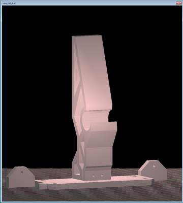
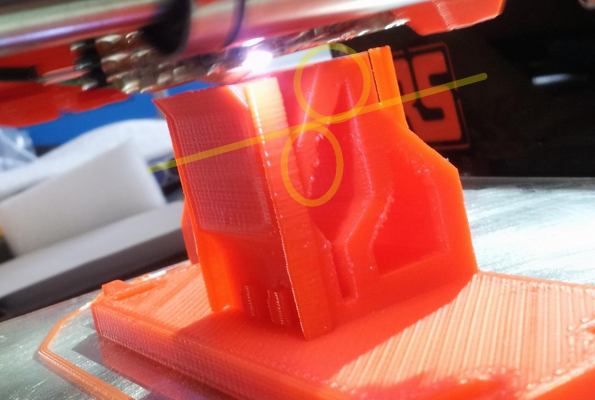
Ii used Slic3r 1.0.0RC2 to slice this One-piece Ormerod bed support. and instead of looking like the preview:
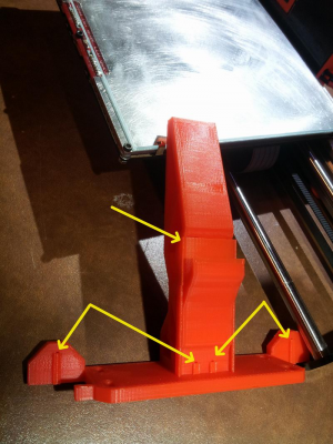
It printed like this:
Wherever there was a hole as arrowed, a vertical bar covers it and drops down from the hole all the way to the bed. Crazy.
The large radius hole for the front bearing is walled-off completely.
Does anyone know what's making this happen?
RS Components Reprap Ormerod No. 481
It printed like this:
Wherever there was a hole as arrowed, a vertical bar covers it and drops down from the hole all the way to the bed. Crazy.
The large radius hole for the front bearing is walled-off completely.
Does anyone know what's making this happen?
RS Components Reprap Ormerod No. 481
|
Re: Why did slicer do this... May 19, 2015 05:32PM |
Registered: 9 years ago Posts: 638 |
|
Re: Why did slicer do this... May 19, 2015 05:34PM |
Registered: 9 years ago Posts: 1,699 |
|
Re: Why did slicer do this... May 19, 2015 06:48PM |
Registered: 10 years ago Posts: 300 |
Thanks, yes, support was enabled but I didn't expect the solid vertical beams outside the holes. It's been a total nightmare to remove them.Quote
Darathy
i belive you have supports enabled in slic3r, it will fill the holes to make easyer bridging on top of the hole and keep dimensions.
Slic3r tells me I'm running the latest when I check for updates from the help menu but it looks like that may be telling fibs. Website says otherwise!
I will have to do a manual update to 1.1.7 or is the experimental release 1.2.6 OK to use yet?
RS Components Reprap Ormerod No. 481
|
Re: Why did slicer do this... May 19, 2015 06:50PM |
Registered: 9 years ago Posts: 1,699 |
|
Re: Why did slicer do this... May 20, 2015 12:50AM |
Registered: 9 years ago Posts: 177 |
Slic3r 1.2.6 also has a preview, you can see a 3D preview of the gcode as well as a layer by layer 'blueprint' of the extruded paths.
Very helpful in seeing how supports will print, or catching any issues slic3r might have. The previews have saved me some time, and filament that I would've otherwise wasted on prints with odd glitches or silly mistakes.
I'll admit this experimental version has some problems, some objects will cause it to crash no matter what. And it crashed randomly. But I think the extra features are worth the hassle of the added bugs.
|
Re: Why did slicer do this... May 20, 2015 08:55AM |
Registered: 10 years ago Posts: 2,472 |
A large horizontal hole needs support to print satisfactorily because near the top of the hole the overhang angle becomes too steep to print without support. Smaller holes will usually muddle through because the steep overhang is only for a couple of layers.
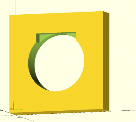
If you don't want to use support the usual workaround is to make a rectangular cutout at the top of the hole that starts at the point where the overhang reaches 45 deg (about 85% of the hole diameter from the bottom of the hole). The image shows such a cutout - I've made it only halfway through the hole for illustration, it would usually extend all the way through.
If the design allows it, you could put a flat at the top of the hole rather than a cutout.
Dave
|
Re: Why did slicer do this... May 20, 2015 09:13AM |
Registered: 10 years ago Posts: 300 |
Thanks for the tip Dave. The obvious question is why a wide bridge across the rectangular cutout would be more successful than the attempt at a steep overhang. However, the cumulative curling-up that seems to result from too steep an overhang may be the answer as it can get into a right mess!
RS Components Reprap Ormerod No. 481
RS Components Reprap Ormerod No. 481
|
Re: Why did slicer do this... May 20, 2015 10:36AM |
Registered: 10 years ago Posts: 2,472 |
Quote
Radian
Thanks for the tip Dave. The obvious question is why a wide bridge across the rectangular cutout would be more successful than the attempt at a steep overhang. However, the cumulative curling-up that seems to result from too steep an overhang may be the answer as it can get into a right mess!
On an overhang there is a thin wedge-shaped edge hanging in mid-air. The thin edge heats up enough to soften as each successive layer is added - the more shallow the angle, the greater the length that gets soft. The top of the thin wedge cools faster than the bottom after each pass of the nozzle (because the bottom is more insulated and gets heated by the bed), and the outer edge, being thinner, also cools faster than the inner part. An object that cools unevenly experiences a force that tries to bend it in the direction of the cooler side (which is contracting faster). The inner side is anchored and cannot move up or down, and so the outer, softened part of the overhang tends to bend upwards. The curl-up accumulates and gets worse with each layer.
On a bridge however, both ends are firmly stuck to the bulk of the print below so neither end can move up or down. The same contraction force will try to bend the bridge, but in that case as the ends cannot move up, it will result in the middle curving down a little (sagging - also exacerbated by gravity). That effect is however offset by the fact that the entire strand contracts and so tends to pull tight and straighten like a banjo string. This central curl-down leaves a larger layer gap for the next pass and so is filled in and becomes less rather than accumulating and becoming worse as the layers build up, and also while one edge of an overhang will remain thin, all of the bridge becomes thicker and stiffer with each layer which decreases the amount of downward curl (sag) for each layer.
To minimise curl-up you can (1) cool the entire extrusion faster so less of the thin overhang section gets soft enough to bend. (2) Do not use a heated bed, or keep it as cool as possible so the bottom does not stay much hotter than the top. (3) Prevent the top surface cooling faster than the lower surface. (1) is accomplished by means of directing a cooling airstream near the nozzle, (2) could be achieved by using a bed coating that causes the first layer to stick with a cooler or unheated bed, and (3) is accomplished by putting the printer inside a heated chamber.
What should also work but I have not seen tried is to direct a stream of hot air downwards from above onto an overhang, which should either lessen the curl-up or cause it to curl down instead (which like a bridge tends to be self-healing). I may try using a hot-air gun on a low heat setting to baby my next print that has an overhang and see whether it works. The air should not be hot enough to melt the plastic, just hot enough to keep the top surface as hot as the bottom surface of the overhang.
Dave
|
Re: Why did slicer do this... May 20, 2015 02:29PM |
Registered: 10 years ago Posts: 300 |
Quote
dmould
...What should also work but I have not seen tried is to direct a stream of hot air downwards from above onto an overhang, which should either lessen the curl-up or cause it to curl down instead (which like a bridge tends to be self-healing). I may try using a hot-air gun on a low heat setting to baby my next print that has an overhang and see whether it works. The air should not be hot enough to melt the plastic, just hot enough to keep the top surface as hot as the bottom surface of the overhang.
Great explanation Dave - you know I like to understand the underlying causes of these issues.
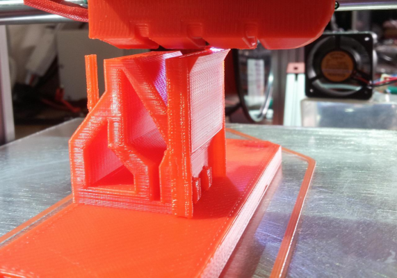
I noticed that the side of an object cooled by the vents pointing at the nozzle was doing a clean overhang yet the opposite side (sheltered from the vents) was curling up - so I grabbed another 40mm fan mid way through the print and positioned it to blow on the overhang.
The side getting cool air:
The opposite side. Horizontal line marks when I started cooling this side:
RS Components Reprap Ormerod No. 481
|
Re: Why did slicer do this... May 20, 2015 07:13PM |
Registered: 12 years ago Posts: 1,611 |
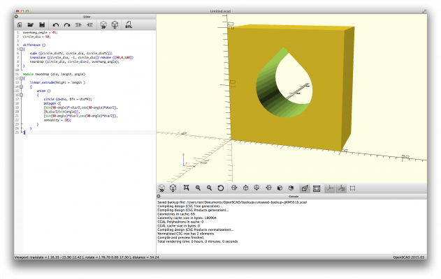
On the subject of horizontal holes, and dealing with an overhang, the other option is to go up at an angle to a point. It's what the original reprap logo is supposed to show, rather than a 'drop' of melted filament, as is often assumed! Here's a quick OpenSCAD script, which lets you play with the overhang value.
Ian
RepRapPro tech support
overhang_angle = 45;
circle_dia = 10;

difference ()
{
    cube ([circle_dia*2, circle_dia, circle_dia*2]);
    translate ([circle_dia, -1, circle_dia]) rotate ([90,0,180])
    teardrop (circle_dia, circle_dia+2, overhang_angle);
}

module teardrop (dia, length, angle)
{
    linear_extrude(height = length )
    {
        union ()
        {
            circle (d=dia, $fn = dia*4);
            polygon ([
            [sin(90-angle)*-dia/2,cos(90-angle)*dia/2],
            [0,dia/2/sin(angle)],
            [sin(90-angle)*dia/2,cos(90-angle)*dia/2]],
            convexity = 10);
        }
    }
}
Ian
RepRapPro tech support
|
Re: Why did slicer do this... May 20, 2015 07:27PM |
Registered: 12 years ago Posts: 1,611 |
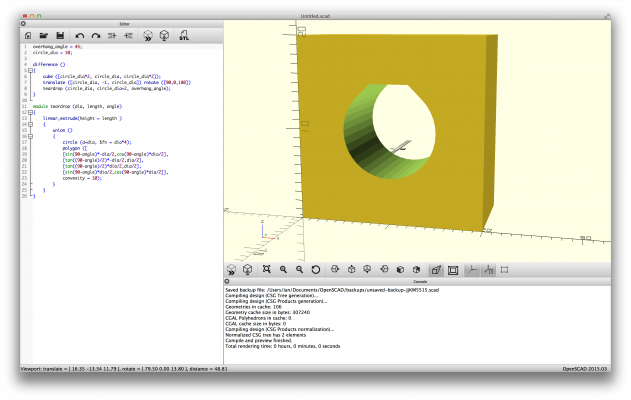
A further improvement would be to flatten the point, and bridge across at the top of the circle, like dmould suggests, but a bit more elegant - sorry, Dave!
Ian
RepRapPro tech support
Edited 1 time(s). Last edit at 05/20/2015 07:33PM by droftarts.
overhang_angle = 45;
circle_dia = 10;

difference ()
{
    cube ([circle_dia*2, circle_dia, circle_dia*2]);
    translate ([circle_dia, -1, circle_dia]) rotate ([90,0,180])
    teardrop (circle_dia, circle_dia+2, overhang_angle);
}

module teardrop (dia, length, angle)
{
    linear_extrude(height = length )
    {
        union ()
        {
            circle (d=dia, $fn = dia*4);
            polygon ([
            [sin(90-angle)*-dia/2,cos(90-angle)*dia/2],
            [tan((90-angle)/2)*-dia/2,dia/2],
            [tan((90-angle)/2)*dia/2,dia/2],
            [sin(90-angle)*dia/2,cos(90-angle)*dia/2]],
            convexity = 10);
        }
    }
}
Ian
RepRapPro tech support
Edited 1 time(s). Last edit at 05/20/2015 07:33PM by droftarts.
|
Re: Why did slicer do this... May 21, 2015 04:10AM |
Registered: 10 years ago Posts: 300 |
Well I never. That has to be the first time a company logo has been inspired by a shortcoming of the technology it employs.Quote
droftarts
On the subject of horizontal holes, and dealing with an overhang, the other option is to go up at an angle to a point. It's what the original reprap logo is supposed to show, rather than a 'drop' of melted filament, as is often assumed!
I'm only joking - it's all quite brilliant really!
RS Components Reprap Ormerod No. 481
|
Re: Why did slicer do this... May 21, 2015 08:02AM |
Registered: 10 years ago Posts: 2,472 |
Quote
droftarts
A further improvement would be to flatten the point, and bridge across at the top of the circle, like dmould suggests, but a bit more elegant - sorry, Dave!
No need to apologise - its a good point that I will adopt in future - thanks for including the OpenScad code which I will now steal from you and use as my own!
Dave
|
Re: Why did slicer do this... May 21, 2015 08:13AM |
Registered: 10 years ago Posts: 2,472 |
Quote
Radian
I noticed that the side of an object cooled by the vents pointing at the nozzle was doing a clean overhang yet the opposite side (sheltered from the vents) was curling up - so I grabbed another 40mm fan mid way through the print and positioned it to blow on the overhang.
Yes, I had forgotten to mention that aspect. I have blocked off the nozzle vents on my Ormerod because I print only in ABS and any cooling is undesirable with ABS except when printing overhangs and bridges (because it increases the tendency to warp), so it does not apply for me. On a standard Ormerod with cooling nozzles, always try to orient your print on the build plate so that the thin end of any overhang is pointing to the left when viewed from the end of the X-arm. i.e. in the photograph you show, you should get a better result on that overhang by rotating the part 90 degrees anti-clockwise on the build plate.
Dave
Sorry, only registered users may post in this forum.
