Ormerod from RS
Posted by ROBBED666
|
Ormerod Electrics troubleshooting December 09, 2013 01:46AM |
Registered: 10 years ago Posts: 9 |
pault [ PM ]
Electrics troubleshooting
December 08, 2013 11:53AM Registered: 4 days ago
Posts: 1
Oops I moved this from New topic as I thought it would go in the Ormerod from RS section.
Ormerod Mechanical build of No 31 completed...near 20 hours.
Tool list is very incomplete, probably better not to include this unless it is 100%.
Fasteners comments re sizes etc similar to other posts so not repeated.
I will be requesting, later, replacement 3 way housings.
My current concern is with power and bootup.
1. The downloads and PC install may have gone Ok, but not tested as I cant see the USB com port yet, although the duet USB light is on.
2. The only electric test given in destructions is to see the Lan lights ...not coming on here.
3. I have 12v at main power cable into duet PCB.
4. Hot end fan spins, blowing out the back, I hope that is the right way!
5. I need more info for testing electrics.
6. I have concerns about the hot bed ribbon connectors. It is usual to have pin1 marked on the PCB or a keyway to orient these correctly. The instructions are a little too vague on this, and no pin1 Identity on duet. I may have them the wrong way round?
So unplugged the 26w conector. Still no see Lan lights.
The Lan cable is tested and OK.
I have looked at the SD card and it has 8.4MB of files so likely OK.
There is no evidence here that the duet is booting...how can I test this?
|
Re: Ormerod Electrics troubleshooting December 09, 2013 05:25AM |
Registered: 10 years ago Posts: 9 |
Further to this.
Meter shows 12v present but no 5v on Duet.
I have downloaded the duet schematic and layout drawings, together with the data sheet for Buck regulator ic A4403.
These indicate that to get the 5v supply running a jumper should be fitted to either JP9 to enable this regulator source or to JP10 to get 5v from ATX PSU. This latter seems irrelevant as only 12v is connected from supplied PSU.
So I added JP9, still no 5v.
Help?
|
Re: Ormerod from RS December 09, 2013 10:46AM |
Registered: 12 years ago Posts: 116 |
Hi pault
We've been investigating this problem.To work from the 12V connector, JP9 DOES need to be in place, to supply 5V to the rest of the board. Without it, the logic side of the board can only be powered by USB. However, you may have a short circuit, caused by a mis-placed connection, or the 12V to 5V regulator may not be working, or both.
You should be able to test the board by unplugging all wires, removing the SD card, and plugging in just the USB, which should light an LED on the board. Plugging in the Ethernet port should give you access to that.
A couple of notes about your other comments:
The hot end fan should blow INTO the hot end, not out. Check you have air coming out of the nozzles around the hot end. You may just be feeling backwash from the fan, of course.
Polarity doesn't matter on the heated bed ribbon cable or thermistor. It can plug in either way around, though make sure it isn't misplaced on the pins.
Let me know if that helps.
Ian
RepRapPro tech support
|
Re: Ormerod from RS December 09, 2013 11:56AM |
Registered: 10 years ago Posts: 191 |
Hello,
just to make it clear: J9 has to be jumpered (shorted) that the duet board works from the 12V ATX PS?
Markus
Edited 1 time(s). Last edit at 12/09/2013 12:08PM by markbee.
XBee & electronics blog: [lookmanowire.blogspot.com]
just to make it clear: J9 has to be jumpered (shorted) that the duet board works from the 12V ATX PS?
Markus
Edited 1 time(s). Last edit at 12/09/2013 12:08PM by markbee.
XBee & electronics blog: [lookmanowire.blogspot.com]
|
Re: Ormerod from RS December 09, 2013 12:20PM |
Registered: 10 years ago Posts: 191 |
@pault: Regarding the 26-pin connector you can check the two middle pins (that are the two leads from the heatbed thermistor) if there is a resistance about 11 kOhm (at room temperature). The twelve pins left and right to it should all have no resistance among themselves (~0 Ohm). Both tests only require a simple DMM (multimeter).
I think they used 12 pins together to get the high amount of power to the heatbed for both positive and negative supply (one or two wires would not be sufficient to transmit the current). As far as I can see polarity does not matter, so the only thing to be sure is that the two middle connectors are not shorted or connected to the two twelve pin groups in any way.
If you connect the duet board via USB to the Arduino IDE, choose the right board (Arduino Due), the correct port (with "programming USB"). Then turn on the serial monitor (either via menu or the far right icon at the top). Select 115200 baud an newline in the serial monitor.
You then should enter M105 + Enter and it should give the temperatures of extruder block and heatbed.
Markus
Edited 1 time(s). Last edit at 12/09/2013 12:23PM by markbee.
XBee & electronics blog: [lookmanowire.blogspot.com]
|
Re: Ormerod from RS December 09, 2013 12:34PM |
Registered: 12 years ago Posts: 116 |
Hi Markus
Usually, yes, JP9 should be jumpered to get 5V power to the logic side of the board from the 12V supply. However, we're investigating an issue: some boards don't have 5V from the 12V power, even when JP9 is jumpered. However, they should work fine, so long as 5V power is supplied via USB.
Ian
RepRapPro tech support
|
Re: Ormerod from RS December 09, 2013 12:50PM |
Registered: 10 years ago Posts: 191 |
Just had a quick look at Duet schematics and the actual board (pcb). The input protection diode ss3p4 (D1) has lots of solder paste applied. Maybe that was too much on some boards? Just a guess. I may put a photo on somewhere to verify.
I did not connect my board to 12V yet, but it works from USB with the aforementioned procedure.
Markus
XBee & electronics blog: [lookmanowire.blogspot.com]
I did not connect my board to 12V yet, but it works from USB with the aforementioned procedure.
Markus
XBee & electronics blog: [lookmanowire.blogspot.com]
|
Re: Ormerod from RS December 09, 2013 01:16PM |
Registered: 10 years ago Posts: 314 |
Hi, I got my Ormerod fairly early #007, but had to wait for a time slot to start constructing, which may have been to my adantage!
Started yesterday and after 5 hours got X, Y and Z completed and today started the extruder.
A point to help others is I did not at first realise I could click a picture and make bigger than full screen! This helped enormously in identifying some of the parts and seeing the fine detail of assembly.
At my current stage, I also initially tried to place the filament feed assembly in the slot closest to vertical axis, but there is no room to do the tilt action required to locate. No problem for me with two other locations for my mono requirements, but something to watch out for.
I particularly found the text around the Z axis assembly lacking in detail and had to view other images to understand the requirements. This was due to the drive cog not being in the picture and no actual assembly view. Simple once you know how!
Washers! I seem to run out of these after the stage of mounting the Z drive bearings 5 off under each bearing and one elsewhere. This used up my last eleven. Also another pack contained one washer and that step required 3. So add at least 6 for up to this step in the process and a few more for luck.
My X and Y motor drive pulleys did not fit the shaft due to distotion at the grub screw tapping. Easily cured with a file, but caused injury to my knuckles while trying to remove it! So watch out....
Looking back I also found the insertion of washer and nuts into the slots of laser cut parts extremely fiddly. You need to improve this part. Possibly using locknut style parts with an effective washer in the design?
What is happening regarding the electronics/electrics are there issue with this?
I see mention of a missing link, wrong connector case and pin out and other posts, so will there be a 'correction' added to the build, so the first 500 know what to change?
Also on the DesignSpark page there is mention of 'blown' controller cards on the Ormerod, but I couldn't see these posts, any comments?
So far it looks a great product.
P.S. I think a seperate Ormerod topic in the Forum would also help us who are not familiar with the other products.
|
Re: Ormerod from RS December 09, 2013 02:46PM |
Registered: 10 years ago Posts: 314 |
|
Re: Ormerod from RS December 09, 2013 03:00PM |
Registered: 10 years ago Posts: 314 |
I may be loosing it and should take a break, but........
In the 'hot end assmbly it states "M3 x 16mm cap head screws Hardware 2" required to mount to the X arm, but photo shows counter sunk and the part has a countersink hole to mate with. Kit does not contain any countersunk screws of that size, but does contain the socket heads!
Sorry if already reported, but web does not show any updates on this yet.
|
Re: Ormerod from RS December 09, 2013 03:16PM |
Registered: 10 years ago Posts: 191 |
There were no more countersunk screws available in my kit so I took the cap head screws and it worked. Pictures show indeed countersunk screws.
Markus
Edited 1 time(s). Last edit at 12/09/2013 03:37PM by markbee.
XBee & electronics blog: [lookmanowire.blogspot.com]
Markus
Edited 1 time(s). Last edit at 12/09/2013 03:37PM by markbee.
XBee & electronics blog: [lookmanowire.blogspot.com]
|
Re: Ormerod from RS December 09, 2013 03:51PM |
Registered: 10 years ago Posts: 314 |
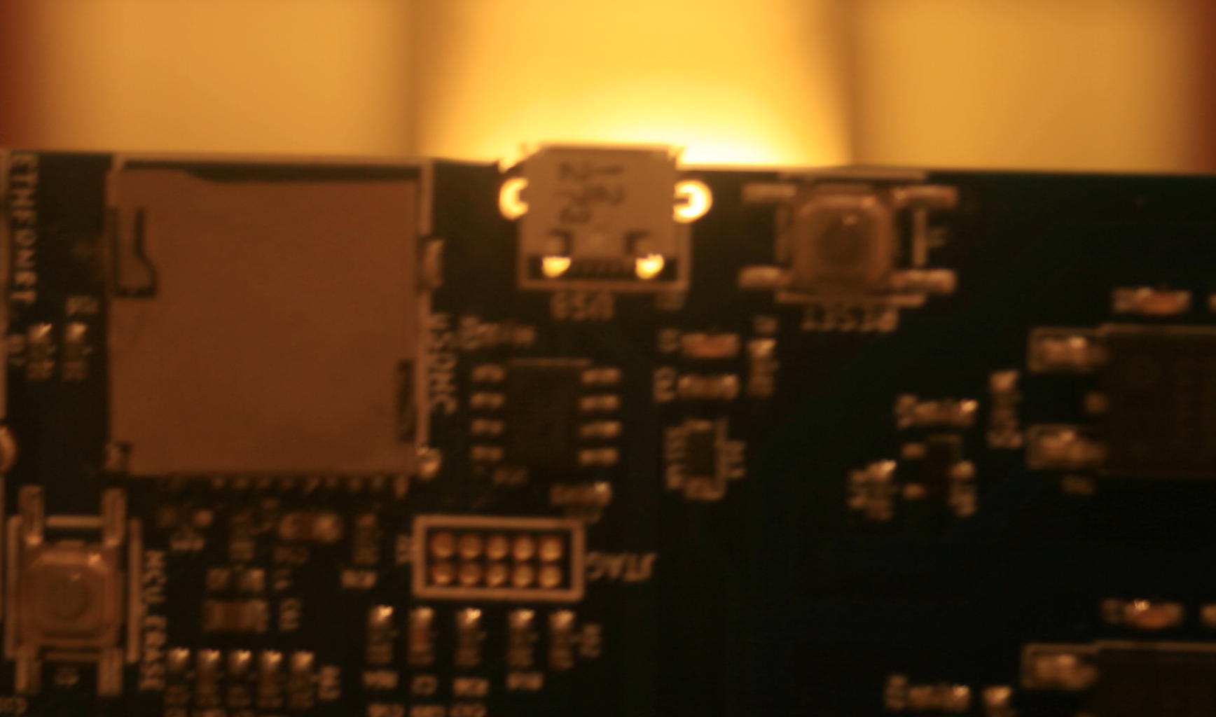
I have just done a check on my board and all the SM components and soldering appear OK, BUT the usb connector does not have any of the four mounting holes soldered!!! I can see right past the lugs and through the holes (x3.5 magnifier). All that is holding the connector I my board as far as I can see is the press fit of the lugs and the soldered connection.
I've attached a low res and blured picture (not my best shot!), but it highlights the issue.
What should be done now?
I've attached a low res and blured picture (not my best shot!), but it highlights the issue.
What should be done now?
|
Re: Ormerod from RS December 09, 2013 04:12PM |
Registered: 10 years ago Posts: 314 |
One final question for the PCB enclosure.
Do the M4 button head screws self tap into the top of black RS logo cover?
And presumably I drill out the lower three holes to clear the M4 thread and allow rotation in the T slots?
I'm also a lucky one who has to drill out the 4 holes on the PCB.....
Over and out....
Do the M4 button head screws self tap into the top of black RS logo cover?
And presumably I drill out the lower three holes to clear the M4 thread and allow rotation in the T slots?
I'm also a lucky one who has to drill out the 4 holes on the PCB.....
Over and out....
|
Re: Ormerod from RS December 09, 2013 04:58PM |
Registered: 12 years ago Posts: 1,611 |
Hi Treth
Many thanks for your feedback. Yes, the instructions are subject to a fair amount of amendment and revision at the moment, a lot based on feedback from the adventurous souls who jumped on board early ... sorry for any inconsistency.
I think we have implemented many of the things you have suggested; I've been updating the text for the Z axis assembly, and the Y carriage construction and order today, and added many pictures. I'm getting on to adding the pictures of the Z drive too. I'll add a note early on in the instructions to say to click on pictures for a larger view.
Despite what I said to Markus yesterday, I believe we have made one change to the fasteners, and that is to add in at least another 10 washers. Though I think this happened after the first 100 kits.
Nozzle mount screws: use cap head screws, as per the BoM table. You can blame Adrian Bowyer for using the countersunk screws; he did the pictures and wrote those instructions! I'll take a new picture with the correct screws tomorrow.
Electronics: The Duet is designed to work independently, running from 12V power. You will need a jumper on JP9, which supplies the logic part of the board with 5V. We appear to have omitted the jumper from all kits. Some customers have reported that, even with a jumper on JP9, they don't get 5V - we're investigating why this might be. However, plugging in a USB cable from a power source (PC, laptop, or powered USB hub) gives the board 5V, and it should then works correctly. Let me know if it doesn't.
Not sure about the USB port lugs; I'll look into it tomorrow. Yes, the top two button heads self tap, the bottom two should pass through and bolt into the extrusion. I'll update the text...
Ian
RepRapPro tech support
|
Re: Ormerod from RS December 09, 2013 05:13PM |
Registered: 10 years ago Posts: 191 |
Hi
I'm just into the electronics/ firmware/ network
I am able to communicate via the Arduino IDE and the Duet board as described in the instructions.
Now I tried to communicate via network. I changed the network parameters on the SD card (IP and Gateway) according to my network in sys/config.g
But when I start/ reset the board w/ a network cable plugged in (this cable works well with another device) no ORANGE light at the network jack comes on at all.
No communication via Chrome browser with the provided IP and not even a ping reply on the console.
This was with the firmware that came with the board and also after updating the RepRapFirmware.bin nothing changed.
Any suggestions?
P.S. Add some M3 nuts too. I had about 5 less than needed.
BTW I now have powered the board via the ATX PSU and until now no problems.
Markus
XBee & electronics blog: [lookmanowire.blogspot.com]
|
Re: Ormerod from RS December 09, 2013 06:13PM |
Registered: 10 years ago Posts: 24 |
|
Re: Ormerod from RS December 10, 2013 03:11AM |
Registered: 10 years ago Posts: 314 |
Hi Ian, thanks, yes the extra pictures and text looks most useful.
I just discovered that clicking on a printed part name opens the STL viewer, most useful, but was not obvious to me during my build! I should 'click' more often!
Regarding the parts list two minor edits required for the "X-axis mounting" components list.
Z-bearing-clamp, quantity should be two.
Z-gear not shown in any photo.
I'm sure this is on your list to update next, but it was here I was unsure of the Z-gear and z-nut-trap and their location as they do not appear in the images.
|
Re: Ormerod from RS December 10, 2013 03:12AM |
Registered: 10 years ago Posts: 191 |
From the serial console of the Arduino IDE the command "M503" should give the content of the config.g.
This doesn't work with the supplied SD card -"file not found".
I took another SD card I had lying around and copied the files onto it.
Now I could read the config.g file from the serial console but still no luck with a network connection - no amber light at all.
Both SD cards are FAT32 formatted.
Markus
XBee & electronics blog: [lookmanowire.blogspot.com]
|
Re: Ormerod from RS December 10, 2013 05:05AM |
Registered: 10 years ago Posts: 314 |
|
Re: Ormerod from RS December 10, 2013 05:47AM |
Registered: 10 years ago Posts: 578 |
I've hit many of the issues already described in this thread, and posted them to two threads on emakershop fourms over the weekend. Some of my issues were resolved by flashing the firmware with Saturday's build, but I still can't get the Ethernet connector to come live so haven't been able to use the web interface to control the printer.
I've had no luck printing with pronterface - although this does allow manual control, it stalls on line 0 of a print job (even simple exercise jobs such as circle.g which only moves the motors and doesn't involve heaters/extruder). I have more success using repetier host on the Mac - though it appears that config.g isn't being run on startup, and "Fake OK" has to be hit a few times to clear the backlog of commands, then M555 P2 has to be sent manually to start emulation of Marlin, after that print jobs will run (including config.g - though after this it still seems to require a hit on "Fake OK" to get print jobs to start).
I have issues with homing - hitting "Home Y" works fine (although stopping short of my actual platform, I'll need to move the Z column back toward the Y motor I guess - I moved it right to accommodate mounting the RS box :| ) Hitting "Home X" causes the machine to retract the X axis (presumably expecting a stop switch) and it eventually crashes into the RS box and judders there for a while. Z homing (using the probe) works fine as does bed compensation, however running ormaxis.g causes the head to crash on X and Z when the axis homing lines are run. I've edited these lines out of ormaxis.g, and I've managed to partially print the parts - what stopped my last run was a reported nozzle temperature of absolute zero during the run which seemed to trigger the PID to try to burn out the heater (lots of smoke from the filament, but I caught it in time before any damage was done). I restarted three times after this, the first time the head temperature was reported still at -273, the second time at +380 and the third time it became responsive again. It seems that disconnecting the thermistor while running gives a latch up at -273, and perhaps one of the connectors came loose momentarily during the run - maybe detecting -273 should be used to switch off the heater/printer as a special case, rather than ramping up the heat.
Ray
|
Re: Ormerod from RS December 10, 2013 06:45AM |
Registered: 10 years ago Posts: 314 |
Hi Ray,
From your comment on the Z axis position and the controller, I think you may have set the distance from the wrong end.
On the web site they now specify it as a new dimension from the opposite end (if memory serves!)
It may also be worth checking the wiring to the thermistor. The thermistor decreases in resistance with temperature increase, so an open circuit will be the coldest.
I hope Reprap revise the program and build some intelligence into themeasurement and control loop to prevent a possible fire hazard!
Possible actions are "if temp measured below a set minimum" require user input to proceed.
"If temp below acceptable working value" don't turn on heater.
"If temp does not reach a set minimum value after 'x' seconds" remove power.
"If temp does not show a set minimum rate of rise after 'y' seconds remove power.
Also some protection during use is also desirable for unattended operation.
Edited 1 time(s). Last edit at 12/10/2013 06:52AM by Treth.
|
Re: Ormerod from RS December 10, 2013 07:21AM |
Registered: 10 years ago Posts: 191 |
@rayhicks
@Ian
Having exactly the some problems
X-axis "crashing"
No print with Pronterface
No Ethernet
Z-Axis homing unstable
...
Markus
XBee & electronics blog: [lookmanowire.blogspot.com]
@Ian
Having exactly the some problems
X-axis "crashing"
No print with Pronterface
No Ethernet
Z-Axis homing unstable
...
Markus
XBee & electronics blog: [lookmanowire.blogspot.com]
|
Re: Ormerod from RS December 10, 2013 07:33AM |
Registered: 10 years ago Posts: 578 |
Hi Treth - indeed, when I built it there was no measurement in the instructions (I just roughly centred the column), when I put the rs box on I had to move it to the right a bit (but moved it too much) and I didn't go back to the z-axis mounting page to notice that it should be 125mm from the right - thanks for pointing out this change in the instructions
I agree on the safeguard stuff - after it happened I managed to reproduce a lock up at -273 by momentarily disconnecting the thermistor, I'll firm up the connections and check that there's no stress on any (as Ian/droftarts suggested in the irc channel) - I just tried this again and indeed the firmware does pick up the problem, bit only seems to output a warning in response :
I thenreconnected the bed thermistor and disconnected the extruder thermistor:
the readings remain latched at -273.1 until the printer is power-cycled.
Ray
Edited 1 time(s). Last edit at 12/10/2013 07:54AM by rayhicks.
I agree on the safeguard stuff - after it happened I managed to reproduce a lock up at -273 by momentarily disconnecting the thermistor, I'll firm up the connections and check that there's no stress on any (as Ian/droftarts suggested in the irc channel) - I just tried this again and indeed the firmware does pick up the problem, bit only seems to output a warning in response :
the above was after momentarily disconnecting the bed thermistorQuote
serial: M105
ok T:-0.1 B:-273.1
Temperature measurement fault on heater 1, T = -273.1
I thenreconnected the bed thermistor and disconnected the extruder thermistor:
Quote
SENDING:M105
serial: M105
ok T:-273.1 B:-273.1
serial: M105
ok T:-273.1 B:-273.1
SENDING:M105
serial: M105
ok T:-273.1 B:-273.1
the readings remain latched at -273.1 until the printer is power-cycled.
Ray
Edited 1 time(s). Last edit at 12/10/2013 07:54AM by rayhicks.
|
Re: Ormerod from RS December 10, 2013 07:58AM |
Registered: 10 years ago Posts: 578 |
Hi Markus,
I've found that manually sending G555 P2 (emulate marlin) kicks it into gear a bit - this command should be executed when config.g runs, which leads me to guess that config.g isn't running on startup. Once I've entered G555 P2 I can "print" config.g and other files, running config.g in this way still doesn't bring up the ethernet connection though
Ray
|
Re: Ormerod from RS December 10, 2013 07:59AM |
Registered: 12 years ago Posts: 116 |
Hi Treth
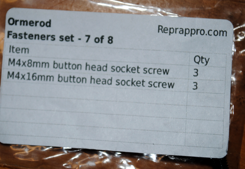
I've done the updates you suggested, though still need to add a couple more pictures. You should have received 5 x M4x16mm button head socket screws and 3 x M4x8mm button head socket screws. You only need 4 and 2, respectively, but we packed one extra of each fastener. What quantities does it say on the fastener bag (7 of 8)? Sorry if you haven't been sent the right amount - might be because you have a really early kit! Let me know if you need me to send you anything, via email - support at reprappro dot com
Ian
RepRapPro tech support
|
Re: Ormerod from RS December 10, 2013 08:09AM |
Registered: 10 years ago Posts: 191 |
@ rayhicks
I will try that later, hope that helps. Thanks
Printing and Ethernet seems to be due to firmware, but just a guess.
X-Axis behaviour: Is there acurrent sensing for the stop/ home position? Mabe the drive belt would have to be observed not slipping in some positions then.
@Ian
I only received 3 M4x16mm and 3 M4x8mm button head screws... (bag 7/8)
Markus
XBee & electronics blog: [lookmanowire.blogspot.com]
|
Re: Ormerod from RS December 10, 2013 08:29AM |
Registered: 10 years ago Posts: 24 |
|
Re: Ormerod from RS December 10, 2013 08:32AM |
Registered: 10 years ago Posts: 314 |
|
Re: Ormerod from RS December 10, 2013 08:42AM |
Registered: 10 years ago Posts: 191 |
For all having the x-axis issue:
I added some white tape to the protruding piece of plastic which is below the proximity sensor when the x-axis is in its 0 position.
Now it seems to work.
Maybe anyone can confirm this?
Markus
XBee & electronics blog: [lookmanowire.blogspot.com]
I added some white tape to the protruding piece of plastic which is below the proximity sensor when the x-axis is in its 0 position.
Now it seems to work.
Maybe anyone can confirm this?
Markus
XBee & electronics blog: [lookmanowire.blogspot.com]
|
Re: Ormerod from RS December 10, 2013 10:05AM |
Registered: 10 years ago Posts: 314 |
I'm getting there.......
Connecting the wiring loom the picture see attached, shows motor "Motor X" plugged in the reverse to all the others - see colours of wires.
I pressume this is an 'art' error?
I'll look elswhere for comments.
Just saw earlier post by Carnivalius December 07, 2013 07:27AM which shows image relating to the 3pin connector shell issue and this shows wiring as per art work! Guess I'll follow suit until I hear otherwise.
Edited 1 time(s). Last edit at 12/10/2013 10:09AM by Treth.


Sorry, only registered users may post in this forum.