Ormerod from RS
Posted by ROBBED666
|
Re: Ormerod from RS December 10, 2013 10:36AM |
Registered: 10 years ago Posts: 314 |
|
Re: Ormerod from RS December 10, 2013 10:54AM |
Registered: 10 years ago Posts: 578 |
@Carnivalius and markbee - thanks - this makes sense, I still hadn't moved my Z axis post over enough, so the head couldn't reach the piece of plastic - seems to work fine for me without white tape. I've found the Z-probe to be pretty sensitive to angle - it's possible to get pretty good readings (between 600 and 700) direct off the Kapton tape at 3-4mm if it's pointing straight down - I removed it earlier and this dropped to 125 until I did some fine positioning (I've removed the foil from my bed and the compensation seems to work fine as does Z homing without it)
@treth - yes to the wiring, motor X is reversed as in the diagram and picture
@treth - yes to the wiring, motor X is reversed as in the diagram and picture
|
Re: Ormerod from RS December 10, 2013 12:00PM |
Registered: 10 years ago Posts: 9 |
More tests on this Duet following advice from RepRap's Ian:
Thanks for speedy response to this.
On 09/12/2013 15:52, RepRapPro Support wrote:
> We've been investigating this problem.To work from the 12V connector, JP9 DOES need to be in place, to supply 5V to the rest of the board.
That is as I thought. Neither the kit or instructions know this! No jumper was supplied.
>>
>> You should be able to test the board by unplugging all wires, removing the SD card, and plugging in just the USB, which should light an LED on the board. Plugging in the Ethernet port should give you access to that.
I have now shed all loads from Duet to eliminate external shorts in my wiring, and I give various test results on the bare board:
> Without it, the logic side of the board can only be powered by USB. However, you may have a short circuit, caused by a mis-placed connection, or the 12V to 5V regulator may not be working, or both.
External 12 v supply gives no voltage at C74 implying the A4403 is not working even with enable jumper JP9 in place.
D1 has 12.39v in and 12.15 out to C3 so OK.
This implies the A4403 is duff or overloaded.
No nasty smells or heat anywhere. No escape of magic smoke has been detected.
External 5v via USB does light the led as already reported but does not enable Lan, no lights at the Lan connector. I checked the incoming 5v from PC USB and the distributed "5v" VBus after the protection Diode D13. Voltages were +4.75 in and Vbus= 4.38.
PC USB = 4.99v off load. That implies current is excessive and dragging the V down.
Tomorrow I will endeavour to measure the current draw in this logic only mode. Please can you quote an expected current. I tried an external 5v 2Amp USB supply which gave values only 20 to 40mv higher so it is not just a poor PC USB output.
With this 5v USB input I measure supply at C54 = 3.24v which seems OK for the 3.3v bus, and 4.35 at C74, which is too low and out of spec. for the 5v bus.
All this evidence points me to think something on the board is dragging the 5v rail low.
However, I don't want to return the board in a hurry yet.
I am a professional electronics engineer so my tests should be reliable and I am willing to take more measurements if you suggest them.
All this email except my address is going on the forum to see if any other duet users want to offer suggestions and help other kit builders.
If you wish to cut to the chase and send me a replacement board, that is fine. Following successful tests with a new one I would return the suspect board.
>
> A couple of notes about your other comments:
> The hot end fan should blow INTO the hot end, not out. Check you have air coming out of the nozzles around the hot end. You may just be feeling backwash from the fan, of course.
> Polarity doesn't matter on the heated bed ribbon cable or thermistor. It can plug in either way around, though make sure it isn't misplaced on the pins.
>
> Let me know if that helps.
I don't want to reconnect loads until board is working correctly.
>
> We will, of course, replace the board if it's faulty, under warranty.
Ta for help, onwards and upwards!
|
Re: Ormerod from RS December 10, 2013 01:03PM |
Registered: 10 years ago Posts: 191 |
One idea might be to supply power via the 5V_IN and GND near the 12V connector. But I doubt that ETH and ARM µC need so much current overloading any of the supply lines for the logic circuits.
Maybe the switching circuit w/ the A4403 has a fault re: the L or C's used there.
Me: no EE
Markus
XBee & electronics blog: [lookmanowire.blogspot.com]
Maybe the switching circuit w/ the A4403 has a fault re: the L or C's used there.
Me: no EE
Markus
XBee & electronics blog: [lookmanowire.blogspot.com]
|
Re: Ormerod from RS December 10, 2013 02:20PM |
Registered: 10 years ago Posts: 578 |
@pault - I measure a steady 100mV on C74 when powering only from the 12V IN and with JP9 in place (with no jumper it floats with hum in the low mV). Measuring the in-circuit powered-down resistance of R60 and R61 gives me 720R for R61 (750R in the schematic), and short circuit for R60 (3k92 in schematic). The output of the regulator is governed by R60/R61 so maybe the apparent short on R60 is to blame for the lack of self-power (although,as markbee pointed out when I discussed it with him, in-circuit measurements aren't the most reliable).
The diodes linking either USB-derived or ATX-derived 5Volts would both seem to drop 550mV as forward voltage, so "+5V" wouldn't get above 4.45V from either of these sources, and only the buck converter would be able to produce 5V on the +5V net I'd guess (presuming that R61 and R 60 are correct). So I'm not sure that there's a huge current draw on the board dropping the +5V net, just the forward voltage of the diode.
The linear regulator used for +3.3V looks to have a 1.2V dropout at current draw of 880mA (worst case) - not sure what current is demanded from it on the board though. A 4.45 feed to a 1.2V dropout regulator is going to make for a marginal +3.3V (@3.25 when the dropout is worst case and the driving 5V is 5.00) though I'd guess, and since the MCU and ethernet run off this, the +5V being low may be a red herring.
Edited 3 time(s). Last edit at 12/10/2013 07:46PM by rayhicks.
|
Re: Ormerod from RS December 10, 2013 06:01PM |
Registered: 12 years ago Posts: 1,611 |
Sorry markbee, missed your message on irc.
Unfortunately, I wasn't able to replicate the ethernet problem... mine worked! Though I did have Adrian Bowyer sat next to me, talking me through it, which helps...
Some notes:
On reset/power on, if the ethernet is not connected, the board can take quite a few seconds to start up.
Check you have put the latest firmware on the board from the DUET branch on github, not the DUE or MASTER branch. Here: [github.com]
5V power needs to be supplied by USB
Connect via USB using the Arduino IDE Serial monitor to check that the SD card is working, and that it's reading the config.g - send M503, and check you get a correct response.
If it isn't, reformat the SD card, or try a different card if you have one available. Copy the files from the Github repository onto the card: [github.com]
You need to set 3 things in sys/config.g for the ethernet to connect; the IP address, the netmask, and the gateway. The gateway shouldn't be too important, that's really for outgoing connections. Check for typos in the config.g file.
Ethernet lead needs to be connected at power up. The ethernet negotiation can take a few seconds, but should flicker if all of the above are correct.
Connect to the board via ethernet using Google Chrome; Firefox doesn't seem to work properly.
Sorry if you've tried all of this; it's mostly what I got from a board that worked first time, thought the SD card seemed a bit flaky.
More tomorrow...
Ian
RepRapPro tech support
|
Re: Ormerod from RS December 10, 2013 07:15PM |
Registered: 10 years ago Posts: 578 |
I think I've done most of that Ian - I'll verify tomorrow, particularly re M503 response and trying a new SD card, but as I've said here and in irc my duet doesn't seem to execute the config.g (even after reformatting the SD) - maybe you can send Adrian or the board you've got working (or better still both) in my direction tomorrow if the steps you suggest fail on my machine (sorry for jumping in on your response to Markus)
(sorry for jumping in on your response to Markus)
|
Re: Ormerod from RS December 11, 2013 02:26AM |
Registered: 10 years ago Posts: 191 |
@Ian I did all this, more than one time on different machines.
Maybe something to think about, what may be a cause of the ETH problems:
The supplied 2GB µSD card does not work. Not initially and not after formatting with FAT32 from different (windows/ linux) machines. I'm now using a 4GB µSD card. I can read the config.g file from the Arduino IDE from the 4GB card with no problems (M503 command).
The amber light on the network jack is NOT flashing/ steady on at all (not at start/ not later). Does that mean the ETH IC doesn't work or is this just a network thing?
My network is on 192.168.178.xx so it is on a different base address then with the default values. In the config.g file I put the 192.168.178.xx address for the duet board (IP address) and 192.168.178.1 for the gateway. Netmask is 255.255.255.0
I resetted all the chrome browser settings.
I can't ping the in the config.g file chosen webserver address.
The IP-address or device doesn't show up in my router at all.
I might try to set up a new network with single router and with no SD card to use the default settings in the Platform.h defined addresses to eliminate any errors due to network or SD card.
Any suggestions appreciated.
EDIT: Short update: Build a new (isolated) network with new router. Duet board doesn't show up in system logs (w/ and w/o SD card) even not in the ARP (MAC address) list. No ping, no trace. Green light on the Duet board network jack flashes and there seems to be network traffic according to the router LAN lights for the port connected to the Duet. Other machines (PC, RasPi, Arduino Ethernet) show up in the router logs with MAC and IP. Strange.
Markus
Edited 1 time(s). Last edit at 12/11/2013 03:32AM by markbee.
XBee & electronics blog: [lookmanowire.blogspot.com]
|
Re: Ormerod from RS December 11, 2013 04:19AM |
Registered: 10 years ago Posts: 314 |
Thanks everyone for comments and reassurances on my questions. My Ormerod is now fully assembled, just need to find a jumper!
@Ian, I found that I had to adjust the orientation of the heater thermistor to allow the cardboard heat insulator orientation to match the heater header pins, i.e. this did not match the orientation shown in the pictures at various stages. No big issue, but something worth checking.
I also found the right hand IDC plug for the heater is touching the wooden cut out, so this should be centralised for future versions (just to look right!)
I also ran out of 3mm nuts at this stage where 12 were required but only 8 remained.
Summary of mechanical and electrical build:
Took longer than expected, I stopped logging after a day! Still not unreasonable, but worth getting a realistic indication.
The parts that required a washer and nut to be inserted in a shaped cutout were very tricky to get all in place! something better like a shaped locknut (look like a nut and washer in one piece) may help?
A couple of parts were not quite right.
1. The slot for the extruder feed nearest the Z-axis is too close to allow the feeder assmbly to be inserted, it clashes with z axis rear bearing mount (not a problem 'til you need 3rd colour!)
2. Heatsink extruder part is not correct size for heatsink depth, i.e. mm gap around heatsink base.
3. Slots for the 12V power leads are too small.
4. Ferrules and/or screw terminal block are not a good match for each other.
5. Metal sprockets for belt drive needed filing out to fit on motor (easy to do, but tricky if not warned and it gets stuck on motor shaft!).
6. I would have liked the electronics case a bit deeper, I'm not sure I'll be able to fit the lid on.
Outstanding:
I have a 50mm printed tube left pressumably for the feed, but where does that go?
Also a flat locking peg which I presume fits in the tube?
Thank you for including some spare crimp pins, I used most of these!
And now to follow the electrical test guide, is there any new "pre test" guidance, i.e. disconnect all connectors and test board via USB etc?
Thanks
|
Re: Ormerod from RS December 11, 2013 05:31AM |
Registered: 10 years ago Posts: 578 |
HiTreth,
I had all the items on your snag list, except my belt sprockets were a good push fit. The ther nut problem I had was getting the captive nuts into the printed slots on the hot end bracket (these needed a lot fo force to insert especially since I didn't do them until the whole thing was built - it might be worth inserting all of these prior to starting the build).
The two pieces you've got left over are the spindle for the filament reel as you've guessed (the tube screws onto the back of the electronics case I believe, but I'll be building a separate stand for mine), the clip goes into the end of the tube and stops the reel falling off.
cheers
Ray
|
Re: Ormerod from RS December 11, 2013 05:37AM |
Registered: 10 years ago Posts: 191 |
Just a little addition to the network issue:
I removed the Duet board and unplugged all the cables to try a basic connection with only USB, Ethernet and SD-Card. But it also didn't work.
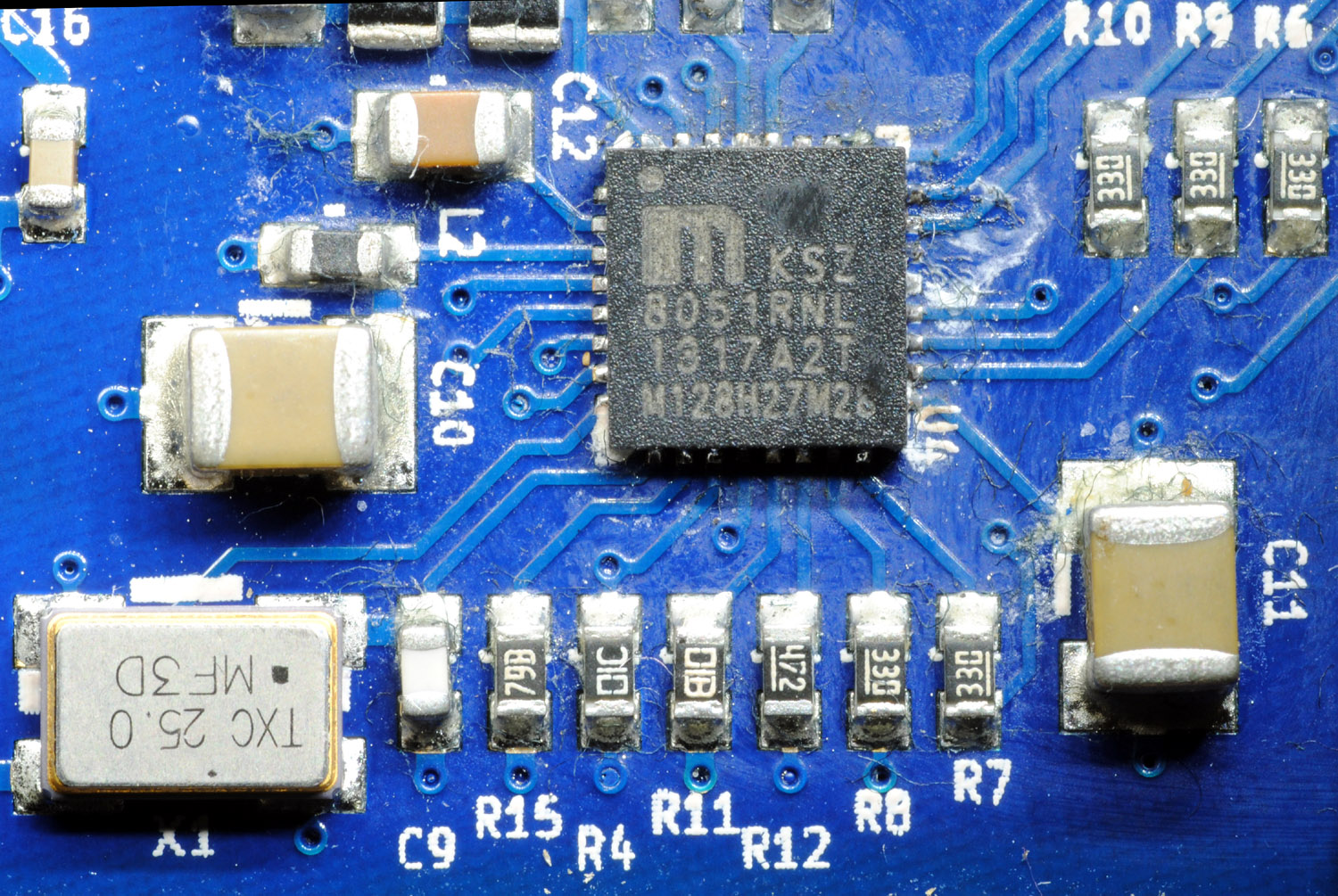
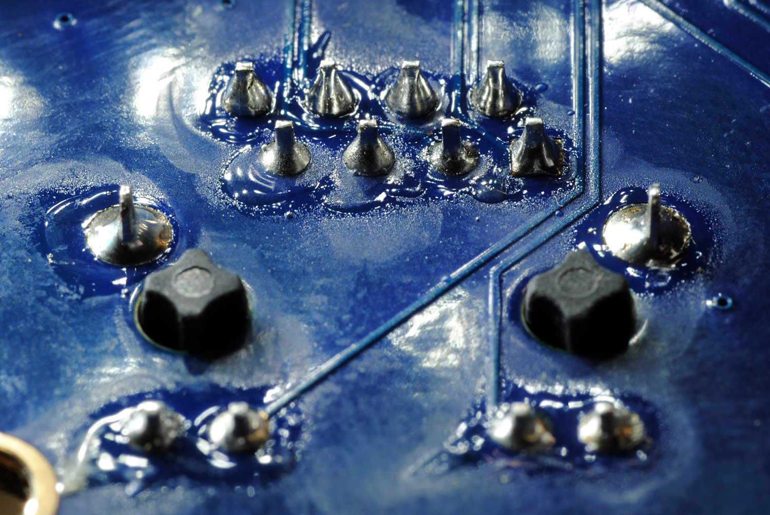
Then I put the pcb under the microscope to rule out any shorts etc. Everything looked good but then - the network IC soldering! Very, very poor. Is that handsoldered afterwards? Even if it is not the cause for the network problems this soldering looks awful. On the bottom (network jack pins) there could even be some cold soldering joints.
Pictures attached (bottom of the network jack, top pcb with KSZ8051RNL)
Next step would be cleaning with isopropanol, or should I send the pcb back straight away?
Markus
XBee & electronics blog: [lookmanowire.blogspot.com]
I removed the Duet board and unplugged all the cables to try a basic connection with only USB, Ethernet and SD-Card. But it also didn't work.
Then I put the pcb under the microscope to rule out any shorts etc. Everything looked good but then - the network IC soldering! Very, very poor. Is that handsoldered afterwards? Even if it is not the cause for the network problems this soldering looks awful. On the bottom (network jack pins) there could even be some cold soldering joints.
Pictures attached (bottom of the network jack, top pcb with KSZ8051RNL)
Next step would be cleaning with isopropanol, or should I send the pcb back straight away?
Markus
XBee & electronics blog: [lookmanowire.blogspot.com]
|
Re: Ormerod from RS December 11, 2013 06:35AM |
Registered: 10 years ago Posts: 314 |
Hi Markus,
Agree IC soldering does not look good, but lead free solder can make it appear much worse than it is. I would wait for official feedback, but as an electronics engineer (but only with permission) I would attempt resolder using flux and solder wick/braid, but in this case I think you need a replacement board.
The image of the connector pins look OK to me.
In your IC picture the diodes D4 and D5 in the top right do not look well placed, I can't see any of the pad in your image, but can see a narrow bit on mine, but my board has not even been powered up yet!
|
Re: Ormerod from RS December 11, 2013 06:54AM |
Registered: 10 years ago Posts: 191 |
Hi Treth,
both diodes are connected to pin 32 (#RST) and they have at least continuity to that pin.
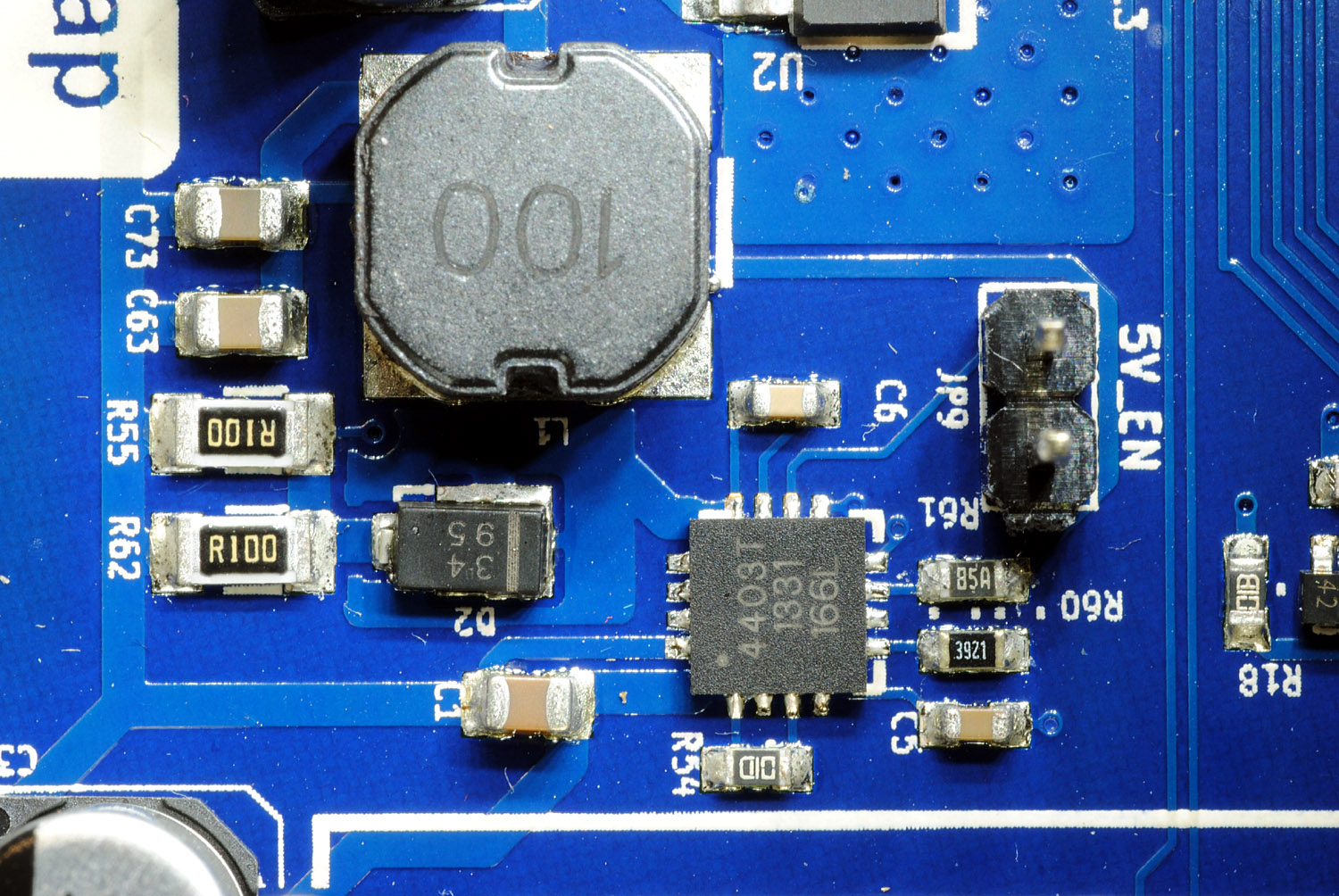
Surprisingly - and that was the reason to post the pictures - all other parts of the board look very good (see the picture of the A4403 buck converter area - that's like all of the top pcb looks like). Only and regional the network IC area is in this bad condition. I doubt this is the cause of the network problems, but wanted to point to it. On the bottom pcb there is a lot of flux, but I doubt this is of a major concern.
Markus
btw Thanks to the Mod moving the thread
XBee & electronics blog: [lookmanowire.blogspot.com]
both diodes are connected to pin 32 (#RST) and they have at least continuity to that pin.
Surprisingly - and that was the reason to post the pictures - all other parts of the board look very good (see the picture of the A4403 buck converter area - that's like all of the top pcb looks like). Only and regional the network IC area is in this bad condition. I doubt this is the cause of the network problems, but wanted to point to it. On the bottom pcb there is a lot of flux, but I doubt this is of a major concern.
Markus
btw Thanks to the Mod moving the thread
XBee & electronics blog: [lookmanowire.blogspot.com]
|
Re: Ormerod from RS December 11, 2013 07:36AM |
Registered: 10 years ago Posts: 314 |
Software clarification!
Right I'm ready to switch on!
To start I was just going to insert the micrSD card in the slot (I'll look at updateing later if problems). I understand that the firmware is ready to run on the Duet.
What do I need on the PC?
I followed a link to Pronterface but the download compiled for Windows zip option seemed to be broken.
[reprappro.com]
Is the above the Arduino IDE mentioned, or is this something else?
Any pointers gratefully received.
@Ray, I did reply to your post (thanks), but I think everything moved in the Forum at the same time, so my response was lost. Basically I had trouble with one of those nuts and left it out. Later when it was needed the nut fell straight into place, so my thoughts were the nut thickness was different. But yes thisarea is an area for RepRap to examine. thanks.
|
Re: Ormerod from RS December 11, 2013 08:11AM |
Admin Registered: 12 years ago Posts: 2,569 |
Treth : pronterface seems to be the recommandation of reprappro : [www.reprappro.com] - maybe try to get it from here : [koti.kapsi.fi]
Otherwise try a test run of Repetier Host.
The arduino ide is only needed if you need to reprogram the firmware into your electronics.
Most of my technical comments should be correct, but is THIS one ?
Anyway, as a rule of thumb, always double check what people write.
Otherwise try a test run of Repetier Host.
The arduino ide is only needed if you need to reprogram the firmware into your electronics.
Most of my technical comments should be correct, but is THIS one ?
Anyway, as a rule of thumb, always double check what people write.
|
Re: Ormerod from RS December 11, 2013 08:22AM |
Registered: 10 years ago Posts: 314 |
Quote
DeuxVis
Treth : pronterface seems to be the recommandation of reprappro : [www.reprappro.com] - maybe try to get it from here : [koti.kapsi.fi]
Otherwise try a test run of Repetier Host.
Many thanks DeuxVis, have now downloaded from "http://kot.......", the RepRap link is still broken.
Thanks for the "Repetier" link that looks useful.
|
Re: Ormerod from RS December 11, 2013 09:56AM |
Registered: 10 years ago Posts: 314 |
Right I'm being a bit 'thick' today! I now have Pronterface for Windows installed thanks to DeuxVis.
I have USB and a network lead connected.
Two LEDS are illuminated on the board and also the network connector has a green led illuminated.
The 12V supply is connected but switched off.
I have the JP9 link inserted.
Pronerface does not see the printer, probably as "Port" is set to "None".
I am not very network savvy, so how do I find the printer via the web browser.
Probably obvious to those who know, but simple steps for me would be most useful. Thanks
|
Re: Ormerod from RS December 11, 2013 10:26AM |
Registered: 10 years ago Posts: 578 |
@treth -pronterface would want to use the usb port, which means you need to install the driver for the Arduino Due - you can get this from the arduino site (you need the 1.5.5 beta or later version with Due compatibility [arduino.cc] ), also read getting started with Due which runs through installation [arduino.cc].
The browser interface may work for you if you have managed to connect your duet to ethernet - launch Chrome (apparently the only supported browser) and point it to [192.168.1.14] (or whatever address you've added in your config for your printer)
Good luck
Edited 1 time(s). Last edit at 12/11/2013 10:39AM by rayhicks.
|
Re: Ormerod from RS December 11, 2013 11:17AM |
Registered: 12 years ago Posts: 116 |
@Treth, DeuxViz
Instructions: [www.reprappro.com]
You DO need to install the Arduino IDE 1.5.5, to include the Arduino Due drivers. Also, the Arduino IDE Serial Monitor works very well at getting basic communication and testing done, as described in the instructions.
Virtually any version of Pronterface *should* work with the Duet. However, Pronterface won't respond correctly until the config.g on the SD card is being read correctly, or you send M558 P2 to the Duet via the Arduino serial monitor. Also, we've made a special version of Pronterface, that is not in compiled form yet, that opens up a couple of special functions.
We haven't even tried Repetier Host, to know whether it works, or causes more problems, and may obfuscate other problems. So please be careful recommending yet more bits of software - it's better for people to work through our instructions.
Ian
RepRapPro tech support
|
Re: Ormerod from RS December 11, 2013 11:27AM |
Registered: 10 years ago Posts: 7 |
@Ian, et al,
I await replacement black acrylic pieces for the X-Axis to correct the varying plate thickness discovered. I had reached the full hardware, with electronics, assembly by the weekend just gone (I purchased Kit #44 - and reckon the full assembly took me three long evening sessions - say 21 hours). But then unfortunately, I had to take time out before looking into getting the electronics up and running. This will have to happen at a later time and when I have rebuilt the X-Axis assembly, so in the mean time I am now watching folk's postings on the forum, re. electronics issues, which is greatly valued. Thank you everyone
Following assembly however, looking from above my Ormerod I can clearly see the X-Axis arm is not perpendicular to the Y-Axis. What is your recommended method to correct this, which I will do when fitting the replacement parts. Oh, and do you know when these might arrive?
Graham.
|
Re: Ormerod from RS December 11, 2013 11:47AM |
Registered: 12 years ago Posts: 116 |
@mandeng
The thickness of the acrylic shouldn't be an issue, so long as it is a linear change along it's length, and neither should the angle of the arm. The whole point of changing the electronics and firmware is to allow for compensation of ALL of the axes. That is, you measure the deviation from straight, and the firmware compensates for it. See the 'Bed Plane Compensation' instructions in 'comissioning' instructions, further down the page here: [www.reprappro.com]
Ian
RepRapPro tech support
|
Re: Ormerod from RS Electrics December 11, 2013 12:51PM |
Registered: 10 years ago Posts: 9 |
More tests as promised:
When using 12v input to Duet and external NO loads, still no 5v generated and current input is 4mA.
Using USB input at measured 4.75v in current load is 320mA...seems reasonable but still no ethernet lights.
As others are finding the 5v buck ic is not working for some reason and there maybe a separate problem with the ethernet.
|
Re: Ormerod from RS Electrics December 11, 2013 01:21PM |
Registered: 10 years ago Posts: 9 |
Duet now removed for close inspection, generally looks well made.
R60 is a two part resistor in parallel, both 0R1 so not measurable on board without special kit.
Most important the pair are mounted at right angles to the layout diagram.
Either pcb tracks have been altered or they are mis-placed.
Please can Ian check if the board actual layout or diagram is correct.
It looks feasible for anyone equipped with SMD tools to remove and re-orient them but only with RepRap's permission....who wants guarantee arguments?
|
Re: Ormerod from RS December 11, 2013 03:07PM |
Registered: 10 years ago Posts: 578 |
@Pault
- R60 on the schematic I've got is 3k92, and R60 on the board is marked as such (3921) it's the upper arm of the feedback divider - nonetheless it appears as a short on my board (and this would actually account for the low output I measure of 100 mV), as I mentioned in an earlier post. The low resistance pair you refer to would be R62 and R55, both 0r1on my schematic and they parallel to give the 0.05r called for in the current-sensing network in the A4403's datasheet
Ray
Edited 1 time(s). Last edit at 12/11/2013 03:10PM by rayhicks.
|
Re: Ormerod from RS December 11, 2013 03:42PM |
Registered: 10 years ago Posts: 24 |
|
Re: Ormerod from RS December 11, 2013 04:40PM |
Registered: 10 years ago Posts: 7 |
@Ian,
I take your point re. X-axis alignment and the varying thickness of the X-carriage to not be significant.
With regard to the print head X-axis movement, I made an effort to try to remove any rotational slack believing the flat of the print-head assembly, on the other side of the X-carriage to the bearing, should slide along it always touching it, believing that setting the slack to an absolute minimum was important.
Given your comments, I would ask if you can confirm the print head assembly depends entirely on it's weight pulling the 9mm bearing onto the flat of the X-carriage and that this is all that is needed to achieve an accurate X movement, and thus the rotational slack is unimportant? If this is so, then I shall return the 9mm bearing back to its looser first-fitted position where rotational slack exists along the whole length of the X-carriage.
Graham.
Edited 1 time(s). Last edit at 12/11/2013 04:42PM by mandeng.
|
Re: Ormerod from RS December 11, 2013 06:26PM |
Registered: 12 years ago Posts: 1,611 |
Hi Graham
Yes, the X carriage does rely on the weight of the nozzle and fan assembly to keep the bearing in contact with the back of the x-axis-plate. We tend to set the bearing so that the X carriage is horizontal; if you tighten it up too much, it may cause the X carriage to rub on the x-axis-plate, impeding movement. It sounds like you have set yours up like this; I haven't actually tried this, so not sure! Also, the further back the X carriage leans towards the x-axis-plate, the weight of the X carriage has a lesser effect on keeping the bearing in contact.
The other place that is in danger of rotation is in the area of the z-runner-mount, which has two bearings either side of the Z axis aluminium extrusion. Though the X carriage movement isn't in the direction of the rotation, it could cause some wobble. The z-runner-mount holds the extrusion, and you want the two bearings to exert a small amount of pressure on each side of the Z axis aluminium extrusion. It may be that, due to slight imperfections in the print, or slight variability, they don't exert quite enough. If you look closely at a couple of the pictures in the instructions, you'll see that one of the bearings has Kapton tape on it. Another option would be to put a strip or two of Kapton tape on the Z axis aluminium extrusion, along the path of the bearing, just to tighten things up.
I *think* I've answered your question...
Ian
RepRapPro tech support
|
Re: Ormerod from RS December 12, 2013 01:16AM |
Registered: 10 years ago Posts: 25 |
Hello!
I'm new here and are still waiting for the delivery of my Ormerod.
I have followed this topic and I think there is too many different things discussed in this one topic. Why not split the questions in separate topics for example one topic for each of the different subtopics in the Ormerod assembly documentation? At least for topics that are related to building and testing the Ormerod.
Regards
Nils-Olov
|
Re: Ormerod from RS December 12, 2013 05:24AM |
Registered: 10 years ago Posts: 314 |
@Ian, Hi thanks for advice.
I have installed Arduino software, downloaded the firmware, but get stuck at the next stage.
In Windows 7 trying any command similar to:
/usr/local/arduino-1.5.5/hardware/tools/bossac --port=ttyACM0 -U true -e -w -v -b RepRapFirmware.bin -R
fails, I think predominantly because "Program Files (x8s)" has spaces.
So I copied Bossac to a simple folder C:\Temp along with the firmware update.
My command line now becomes:
C:\Temp>bossac --port=ttyACM4 -U true -e -w -v -b RepRapFirmware.bin -R
No device found on ttyACM4
I have checked Device Manager and it states Bossa Program Port(Com4)
Also is there any visible action during an Erase or Reset?
Should there be a minimum delay after pressing erase before continuing with reset?
Advice from everyone is welcome!
|
Re: Ormerod from RS December 12, 2013 05:40AM |
Registered: 10 years ago Posts: 191 |
In windows you have to put the COM-port into the command-line
bossac --port=COM4 -U true -e -w -v -b RepRapFirmware.bin -R
This is for COM4 you have to put in whatever COM-port the Duet board is using.
Markus
Edited 1 time(s). Last edit at 12/12/2013 05:41AM by markbee.
XBee & electronics blog: [lookmanowire.blogspot.com]
bossac --port=COM4 -U true -e -w -v -b RepRapFirmware.bin -R
This is for COM4 you have to put in whatever COM-port the Duet board is using.
Markus
Edited 1 time(s). Last edit at 12/12/2013 05:41AM by markbee.
XBee & electronics blog: [lookmanowire.blogspot.com]


Sorry, only registered users may post in this forum.