Network connection
Posted by Treth
|
Re: Network connection December 26, 2013 04:18PM |
Registered: 10 years ago Posts: 103 |
please see attachment:
My setup is the following:
- Ormerod powered by supply (my board works without US ;
;
- SD card in with I hope all relevant files downloaded from website (SD image);
- Ormerod connect to router (Virgin Media) via a cable;
- Laptop wirelessly connected to router;
From laptop I can access router interface (192.168.0.1) and check who is connected to router;
Ormerod appears with IP 192.168.1.14 and MAC address (see slide one of attachment);
From the advanced settings option of my router I can ping IPs but when I ping the Ormerod (that the router can see) it doesn't work (see slide two of attachment);
So router see Ormerod, ethernet green LED is working but I can ping Ormerod and can't connect to it through Chrome either;
Any idea?
My setup is the following:
- Ormerod powered by supply (my board works without US
;- SD card in with I hope all relevant files downloaded from website (SD image);
- Ormerod connect to router (Virgin Media) via a cable;
- Laptop wirelessly connected to router;
From laptop I can access router interface (192.168.0.1) and check who is connected to router;
Ormerod appears with IP 192.168.1.14 and MAC address (see slide one of attachment);
From the advanced settings option of my router I can ping IPs but when I ping the Ormerod (that the router can see) it doesn't work (see slide two of attachment);
So router see Ormerod, ethernet green LED is working but I can ping Ormerod and can't connect to it through Chrome either;
Any idea?
|
Re: Network connection December 26, 2013 04:39PM |
Registered: 10 years ago Posts: 14,672 |
Have you tried using a different IP address? Some routers like to manage IP addresses in a certain range via DHCP. I changed mine to 192.168.1.80. Also, does the gateway IP address in config.g match the IP address of your own router? I don't know if it matters, but I changed it to the IP address of my own router before I tried connecting.
|
Re: Network connection December 26, 2013 05:47PM |
Registered: 10 years ago Posts: 103 |
|
Re: Network connection December 26, 2013 07:47PM |
Registered: 12 years ago Posts: 1,611 |
@arnaud31: Any network device usually needs to be in the same range as the router. You say this is 192.168.0.1 but the printer is on 192.168.1.200
This might work if you netmask is 255.255.0.0 but not if it is 255.255.255.0
Set the printer ip address to 192.168.0.200 and netmask to (I expect) 255.255.255.0
Ian
RepRapPro tech support
This might work if you netmask is 255.255.0.0 but not if it is 255.255.255.0
Set the printer ip address to 192.168.0.200 and netmask to (I expect) 255.255.255.0
Ian
RepRapPro tech support
|
Re: Network connection December 27, 2013 06:10AM |
Registered: 10 years ago Posts: 300 |
Just to confirm, I always see the controls for half a second before it switches to the login page. Logging in is still hit & miss, but hit enough to print off my first few objects yestderday!Quote
dc42
When I connect via Ethernet, I always see the control page briefly before the login page appears. So I think this is normal behaviour.
|
Re: Network connection December 27, 2013 10:32AM |
Registered: 12 years ago Posts: 1,611 |
Quote
Radian
Just to confirm, I always see the controls for half a second before it switches to the login page. Logging in is still hit & miss, but hit enough to print off my first few objects yestderday!Quote
dc42
When I connect via Ethernet, I always see the control page briefly before the login page appears. So I think this is normal behaviour.
Yes, you're right, this does seem to be the correct behaviour. What isn't is if it goes straight to the web interface. This, I think, means the SD card did not supply config.g, or it couldn't find it, but it is finding the www folder on the SD card, to show the web interface.
Ian
RepRapPro tech support
|
Re: Network connection December 27, 2013 05:34PM |
Registered: 10 years ago Posts: 7 |
I have build no 460. Just build it en started testing. I have the network problem.
My network connection works, but only if powered by the micro USB (my laptop).
I searched this forum and found out that there is a solution, Something about wiring from the 12V supply.
I cannot find a good guide with pictures like the build guide that help me tot to solve this issue.
I don't want to solder anything on the Duet, like putting capacitors or things like that. Just like the build instructions crimp some wires, connect it, or put a jumper somewhere is OK.
Otherwise I think there are still serious issues in the design of the board.
Edited 1 time(s). Last edit at 12/27/2013 05:36PM by gampie.
|
Re: Network connection December 27, 2013 06:12PM |
Registered: 10 years ago Posts: 14,672 |
There are a couple of things you can check:
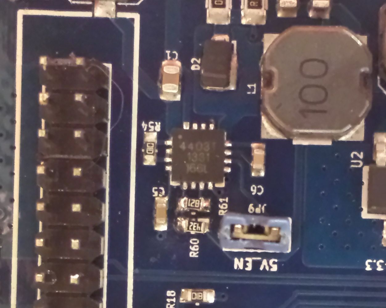
1. Check that there is a jumper across the "5V EN" pins on the Duet board. See attached photo. If there isn't, DO NOT add a jumper in this position until you have done the next check, or you risk destroying some components on the board.
2. Check that components R60 and R62 next to that jumper are the right way round as on the photo, i.e. at right angles to capacitor C5, not parallel to it (they should be on your kit #, but check anyway).
I suggest you wait for an official response from Ian before changing anything. In the meantime, if you have a spare USB wall wart or phone charger, use that to provide the 5V power.
|
Re: Network connection December 28, 2013 04:34AM |
Registered: 10 years ago Posts: 191 |
I have a replacement board and the network connection problems as stated above.
It looks like even my replacement board doesn't provide 5V power - I should have checked that! (I was so sure in the first place the replacement would work...).
So now it's obviously for me, why the network doesn't work for me - looks like I have to replace the board again
Resistors are mounted the right way, jumper (JP9) is set.
I will do some tests with a 5V direct supply (soldering header, JP10 enabled) as mentioned by Ian. Maybe that helps and brings things straight.
Markus
Edited 1 time(s). Last edit at 12/28/2013 04:36AM by markbee.
XBee & electronics blog: [lookmanowire.blogspot.com]
|
Re: Network connection December 28, 2013 05:05AM |
Registered: 10 years ago Posts: 7 |
Thnxs, this works fine. Thanks for the picture.
I had 1 jumper left. The other one is on the other ATX power board.
It would be nice if this instruction was added in the build documentation at this point.
A board layout with explanation of all the pins would also be preferable.
I found a sort of oveview on [blog.think3dprint3d.com] but no pictures in detail or descriptions.
|
Re: Network connection December 28, 2013 05:32AM |
Registered: 12 years ago Posts: 1,611 |
@markbee: Oh no! Sorry that you got another duff board. I'm sure we'll be having discussions about quality control with the manufacturer in the New Year... Email me, I'll send another one, which I'll test this time, before sending.
@gampie: The instructions cover the jumper locations; on this page for the ATX power PCB: [www.reprappro.com] and then the jumper on JP9 on the Duet is covered in the commissioning instructions: [www.reprappro.com]
"Now connect the ATX power supply unit.
The PSU will supply the motors and heaters with 12V, while the logic is supplied with 5V. Make sure that there is a jumper on the JP9 (5V_EN) pins. With no USB lead connected, a light should turn on on the board, near the reset button."
The commissioning instructions do need a few pictures; it's a bit of a wall-of-text, and easy to miss bits out.
The silkscreen on the Duet does a pretty good job of explaining what each pin does. The source files are available here, if you want to investigate further: [github.com]
Ian
RepRapPro tech support
|
Re: Network connection December 28, 2013 09:09AM |
Registered: 10 years ago Posts: 103 |
Hi Ian,
Changing range to same as router .0. instead of .1. doesn't change anything. I still can see the new IP but can't ping it.
Same if I play with the netmask. Basically, router will see any the board with any IP I set on the SD card but will not be able to ping.
I give up now. Will see if anything improves when I pick the new board early January.
|
Re: Network connection December 28, 2013 09:41AM |
Registered: 10 years ago Posts: 14,672 |
Arnaud31, just in case the problem is between the router and the Duet, it might be worth connecting the Duet directly to your computer, disconnecting the computer from the router, and manually setting the computer IP address to one on the same subnet as the Duet.
Large delta printer [miscsolutions.wordpress.com], E3D tool changer, Robotdigg SCARA printer, Crane Quad and Ormerod
Disclosure: I design Duet electronics and work on RepRapFirmware, [duet3d.com].
Large delta printer [miscsolutions.wordpress.com], E3D tool changer, Robotdigg SCARA printer, Crane Quad and Ormerod
Disclosure: I design Duet electronics and work on RepRapFirmware, [duet3d.com].
|
Re: Network connection December 28, 2013 03:41PM |
Registered: 10 years ago Posts: 191 |
I just tested my replacement board with the 5 volt derived from the PSU. The webinterface now seems to work ok. The control page appears for a short while, then the login page. But this time I can log in and see the control and the other pages. I did not print or made other tests yet.
I had first to solder a three pin header to the pads marked J20 on the Duet board. For getting the 5 volt supply to work both left pins of the power pcb (K1) had to be connected to GND on J20 on the Duet board and the right pin of the three header row (K1, power pcb) to 5V_IN of J20.
So it's obvious the step-down regulator (A4403) is again not working on my replacement board. Resistors (R60, R62) are soldered as silkscreen indicates...
Markus
XBee & electronics blog: [lookmanowire.blogspot.com]
|
Re: Network connection December 28, 2013 04:07PM |
Registered: 10 years ago Posts: 300 |
Is JP9 linked with a jumper?Quote
markbee
I just tested my replacement board with the 5 volt derived from the PSU. The webinterface now seems to work ok. The control page appears for a short while, then the login page. But this time I can log in and see the control and the other pages. I did not print or made other tests yet.
I had first to solder a three pin header to the pads marked J20 on the Duet board. For getting the 5 volt supply to work both left pins of the power pcb (K1) had to be connected to GND on J20 on the Duet board and the right pin of the three header row (K1, power pcb) to 5V_IN of J20.
So it's obvious the step-down regulator (A4403) is again not working on my replacement board. Resistors (R60, R62) are soldered as silkscreen indicates...
Markus
RS Components Reprap Ormerod No. 481
|
Re: Network connection December 28, 2013 04:15PM |
Registered: 10 years ago Posts: 191 |

Sorry, only registered users may post in this forum.