Improving the proximity sensor - SUCCESS!
Posted by dc42
|
Improving the proximity sensor - SUCCESS! December 22, 2013 08:28AM |
Registered: 10 years ago Posts: 14,672 |
I'm finding that my proximity sensor is VERY sensitive to ambient light. I already mentioned in another post that when I had a 50W halogen bulb in the ceiling above, I couldn't make it work at all. Now I'm finding that I can't set up parameters that will reliably do the z-homing, because even the sunlight coming through the window is giving quite high readings.
What I really want to do is modulate the infrared emitter and detect just the modulated signal. But until I can build the Duet firmware myself, that isn't an option. However, I think I can improve the performance with some component changes.
The sensor board comprises a TPRT1000 sensor, which houses an infrared emitter and infrared sensor. The emitter is driven from 3.3V via a 160 ohm series resistor, and drops about 1.2V. This means the forward current is about 13mA. The sensor is a phototransistor which has a 15K load resistor on the board. The other component on the board is a 10uF tantalum capacitor for decoupling the 3.3V power.
For any photosensor, there will inevitably be differences in sensitivity between different samples of the device. The datasheet unfortunately gives only typical characteristics. But is seems clear to me that my own sensor is more sensitive than the circuit is optimized for, given the high readings that I get. Also, I did not need to put any tape or foil on the x-homing lug, unlike some other people here.
The device seems to saturate at a reading of about 970. It stays saturated at distances between 0mm and 1mm, and the reading only drops a little at 2mm. So the first change I am going to make is to decrease the load resistor. By itself, I think I need to decrease it by a factor of about 2 to better suit my own TPRT1000.
The second change I plan to make is to increase the forward current, The device is running at 13mA, well below its maximum rating of 50mA. If I increase the forward current to 35-40mA then there will be about three times more reflected IR, which will make the background IR three times less significant. So I plan to reduce the 160 ohm resistor to 51 ohms (I would prefer 56 ohms, but unfortunately I don't have that value in 0603 resistors).
Of course, the higher IR illumination will increase the sensor collector current, so I'll have to further reduce the load resistor. I'll try 2.7K. The power draw from the 3.3V line will go up by about 25mA, but I don't expect that to cause any problems.
Any comments or suggestions from anyone before I try this out?
Edited 1 time(s). Last edit at 12/22/2013 11:13AM by dc42.
|
Re: Improving the proximity sensor December 22, 2013 08:43AM |
Registered: 12 years ago Posts: 116 |
|
Re: Improving the proximity sensor December 22, 2013 09:27AM |
Registered: 10 years ago Posts: 14,672 |
Success! I changed those resistors, and the sensor is much less sensitive to ambient light. I even reinstated the 50W halogen bulb in the ceiling above the Ormerod, and it only increases the reading by about 15. The highest reading I get is now about 770 at 0mm and it drops to 448 at 1mm. So it's just about clear of the saturation region. I'll calibrate at 1mm or just a little higher.
I had to add a piece of aluminium tape on the X lug to make the X homing work.
Edited 4 time(s). Last edit at 12/22/2013 09:47AM by dc42.
I had to add a piece of aluminium tape on the X lug to make the X homing work.
Edited 4 time(s). Last edit at 12/22/2013 09:47AM by dc42.
|
Re: Improving the proximity sensor - SUCCESS! December 26, 2013 04:17AM |
Registered: 10 years ago Posts: 14,672 |
PS:
1. The sensor part number is TCRT1000, not TPRT1000 as I said in my original post. Datasheet here: TCRT1000
2. For anyone else contemplating this mod, I now think the 2.7K load resistor I used could be increased to about 3.9K or perhaps even 4.7K. The important thing is to make sure the reading at the Z-distance you want to use for calibration is below 700.The sensitivity drops off when the reading goes much above that due to the phototransistor starting to saturate. I calibrate at 1mm. I've also found that white PVC tape gives more consistent readings than aluminium tape, see separate post.
Edited 1 time(s). Last edit at 12/26/2013 04:17AM by dc42.
|
Re: Improving the proximity sensor - SUCCESS! December 26, 2013 07:18AM |
Registered: 12 years ago Posts: 1,611 |
|
Re: Improving the proximity sensor - SUCCESS! December 26, 2013 07:44AM |
Registered: 10 years ago Posts: 135 |
Hi All
Interesting developments. I notice on the data for the device that it is possible to modulate the IR and thus eliminate background effects. I have not looked into this at all but assume that this would be a superior aproach. DC42 seems to have done a superb job Ian, the reduced collector resistor compensates for the incresed IR output thus restoring the original sensitivity, the accuracy can only be improved by reducing the impact of ambient light.
This whole affair reminds me of the saga of my Grandmothers TV. She constantly complained the remote would not work, the man would come in the morning and say" look it works fine". I was told of the problem and suddenly the light went on in my head, I switched on the ceiling light and hey presto the remote would not work. New low energy lamp in the ceiling end of problem.
Rory
|
Re: Improving the proximity sensor - SUCCESS! December 26, 2013 07:57AM |
Registered: 10 years ago Posts: 14,672 |
Hi Ian,
I made 2 resistor changes:
1. Reduced the LED drive series resistor from 160 ohms to 51 ohms, in order to increase the current from 13mA to 40mA. This increases the light output by a factor of about 3, and thereby decreases the effect of ambient light by a similar factor.
2. Reduced the phototransistor load resistor by a factor of 5.5. This is partly to compensate for the IR output having been increased by a factor of 3, and partly because my sensor was in the saturation region (reading >700) even at 2mm distance. Yes it does reduce the sensitivity, but the sensitivity is much higher than it needs to be anyway. Calibrating at 1mm with my new resistor values, I get readings around 320, with a variability of about 9 using white PVC tape and much greater variability using aluminium tape. So even if I reduced the load resistor further to get a reading of 100 at 1mm, the sensitivity would still be high enough, considering the variability would still be about 3. However, I may increase the load resistor to about 4.3K, to bring the reading up to around 500 at the 1mm height I want to calibrate at.
Looking at the graph on the sensor datasheet, I think calibration is best carried out at a distance between the sensor and the tape of around 2mm. I estimate that my sensor is at least 1mm higher than the nozzle, that is why I calibrate at a nozzle height of 1mm instead of the suggested value (which was 1.8mm to 2mm AFAIR). If course it is only safe to calibrate at 1mm if the sensor is well out of the saturation region at that distance.
Edited 2 time(s). Last edit at 12/26/2013 07:57AM by dc42.
|
Re: Improving the proximity sensor - SUCCESS! December 26, 2013 08:08AM |
Registered: 10 years ago Posts: 14,672 |
|
Re: Improving the proximity sensor - SUCCESS! December 26, 2013 09:22AM |
Registered: 10 years ago Posts: 135 |
Dc
Well er no you could do it with analog electronics. Perhaps I am just an old .... bought up on op amps. Actually firmware alone may not do the job without more wires to the sensor pcb. At present there is 3.3V, o/p and ground. I would assume having created the modulation signal in firmware some means of getting it to the sensor is required.
Rory
|
Re: Improving the proximity sensor - SUCCESS! December 26, 2013 12:37PM |
Registered: 12 years ago Posts: 1,611 |
|
Re: Improving the proximity sensor - SUCCESS! December 26, 2013 03:04PM |
Registered: 10 years ago Posts: 41 |
|
Re: Improving the proximity sensor - SUCCESS! December 26, 2013 03:13PM |
Registered: 10 years ago Posts: 14,672 |
|
Re: Improving the proximity sensor - SUCCESS! December 26, 2013 04:28PM |
Registered: 10 years ago Posts: 135 |
Ian
Yes you can move the supply line to analogue output but then where do you get the supply for the receive side? I suppose you could rectify and smothe the Square wave to power the receiver side. I have procured/designed a circuit which does not require any firmware or wiring change, this is my prefered option but as I said before perhaps it is a generational thing, everything possible is done in firmware these days.
Rory
|
Re: Improving the proximity sensor - SUCCESS! December 26, 2013 04:50PM |
Registered: 10 years ago Posts: 14,672 |
I've already tried sliding a 4th wire into the sheath of the sensor cable, and it fits easily. I'm planning to either epoxy a 4th header pin to the board, or solder a 4-way header strip to the existing 3-way header strip to make the 4th connection. I would design and order a pcb that incorporates the extra circuitry, but I expect RepRapPro will do that soon enough anyway. So for now I'll just solder the extra transistor and resistor to the existing board and the new header pin. But first, I need to get the firmware building, preferably under either Arduino IDE or AVR Studio.
Edited 1 time(s). Last edit at 12/26/2013 04:52PM by dc42.
Edited 1 time(s). Last edit at 12/26/2013 04:52PM by dc42.
|
Re: Improving the proximity sensor - SUCCESS! December 27, 2013 07:30AM |
Registered: 10 years ago Posts: 25 |
dc42. Why not find an available output pin on the duet board and use it to switch the ir-transmitter on and off. Measure the signal from the receiver when on and off. calculate the difference and use it for the distance to the bed. Maybe the output of the controller can source/sink enough current so you dont need an extra transistor to drive the ir-transmitter?
Ormerod #399 and He3D K200 dual head.
Ormerod #399 and He3D K200 dual head.
|
Re: Improving the proximity sensor - SUCCESS! December 27, 2013 08:21AM |
Registered: 10 years ago Posts: 14,672 |
Hi nof,
According to the specs of the Arduino Due on which the Duet electronics is based, the most current that any of the pins can supply is 15mA source or 9mA sink. I'm running the LED at 40mA to increase the IR output and thereby decrease the effect of ambient light. Even if I accepted a reduction in current to 15mA, I still think that direct drive wouldn't be such a good idea, because the voltage drop of the output pins will be significant at that current, and it increases with temperature. This would cause the IR output and hence the bed height to decrease with temperature. Seeing that the electronics board is not far from the bed which is heated to 110C for ABS printing, and it carries 4 stepper driver chips and a linear regulator that all generate heat, I don't want to risk making the height sensing temperature-sensitive. Hence my plan to have the Duet drive a transistor on the sensor board to switch the LED.
I have toyed with the idea of attaching an attiny45 to the sensor board to make a sensor upgrade that doesn't need any extra Duet pins or firmware changes. The attiny outputs have better current drive capability than the Duet, and I would drive the LED from 3 attiny output pins in parallel to further reduce the voltage drop and hence temperature sensitivity. I would use two of the output pins and an RC network to generate the analog output to feed to the Duet.
Edited 1 time(s). Last edit at 12/27/2013 08:22AM by dc42.
|
Re: Improving the proximity sensor - SUCCESS! December 27, 2013 10:06AM |
Registered: 10 years ago Posts: 41 |
|
Re: Improving the proximity sensor - SUCCESS! December 27, 2013 10:51AM |
Registered: 10 years ago Posts: 14,672 |
Quote
chriscain
You could use the FAN0 output on the Duet
it's connected to the PWM o/p pin with a mosfet and not used on the Ormerod as the fan is on all the time.
would need a higher resistor as it's on the 12v supply.
That's certainly a possibility, although I'm a little concerned that unless I load the power mosfet heavily, it might be very slow to turn off - which might not matter, depending on how the firmware is modified. I would also need to provide a +12V power feed to the sensor board, or else use additional components to protect the sensor LED against 12V reverse voltage. It looks easy enough to add a transistor to the board, I can just cut the ground trace to the LED cathode and solder a BC817 transistor (case style SOT23) across the break. Then add a small resistor (not SMD) to connect the transistor base to the new connection pin.
I took some more measurements today. With the modified component values I am using (which decrease the relative sensitivity to ambient light by a factor of 3), and white PVC tape instead of aluminum tape, the 50W halogen bulb above the Ormerod increases the sensor reading by an amount equivalent to dropping the head by 0.3mm. The sun hasn't been shining here today, but when it was I reckon that the effect of bright sunlight was maybe half the effect of the 50W bulb. So even with the component changes I have already made, I think modulation would be a worthwhile improvement.
|
Re: Improving the proximity sensor - SUCCESS! December 27, 2013 11:07AM |
Registered: 10 years ago Posts: 135 |
Hi Chris
This sounds highly promissing, presumably FAN0 could be switched fairly rapidly and continually but not so fast as the read rate of the A2D input so you get a stream of data background then IR-on and so on. The ballast resistor would need increasing but only to 270R for 40ma forward current. The load resistor will need reducing to 2.7KR as per DC42 experiments to allow for increased current and high background IR, Cut one track on the pcb to seperate the power add a pin for the extra wire and Robert's your mothers brother. Not forgetting the firmware upgrade of course.
DC
I did not see your reply when I wrote this. Surely bright sunlight 2KW/sqm if my memory serves can easily overpower a 50W lamp.
Rory
Edited 1 time(s). Last edit at 12/27/2013 11:36AM by Rory166.
|
Re: Improving the proximity sensor - SUCCESS! December 27, 2013 01:02PM |
Registered: 10 years ago Posts: 14,672 |
Hi Rory.
Yes I would expect bright sunlight to be able to overpower a 50W halogen lamp. But it's winter so the sun is not very high, and it was well past midday when I observed the effect. Also my windows are double glazed, and modern double glazing has a thin metal film on the inside of the glass to reflect IR. I'm not even sure the sun was shining directly on the print bed. These factors may explains why I haven't yet seen sunlight have as much of an effect as the 50W halogen bulb.
Regarding running the IR sensor from the 12V fan output, as I tried to explain in my previous post, you would need to run an extra 12V wire from the Due to the sensor, so 2 additional wires in total. This is because the fan is intended to be connected between the +12V supply and the fan output pin. The 270R resistor would dissipate about (10.8V * 0.04A) = 0.43W. This means you can't just substitute a 270R SMD resistor, since 0603-size resistors are typically rated at just 0.1W.
So I think I'll stick to using a transistor to drive the LED.
|
Re: Improving the proximity sensor - SUCCESS! December 27, 2013 03:28PM |
Registered: 10 years ago Posts: 135 |
Hi DC
Yes I see that using FanO requires 12V, although I assume it would work with a lower voltage than it is intended for(all rails share the same common?). The point about the sunlight is that the output of the photo transistor needs to be kept low in case it is exposed to direct sunlight which might cause a huge increase in output, hopefully one might still pickup the modulation even over a much larger ambient signal. The price you pay is lower resolution. I suspect that if the sensor gave a maximum of 100 at 1.5mm sensor seperation this might be good because even if the ambient pushed the signal up to 900 then the sensor would still just work.( using the assumption that the phototransistor is linear which it probaly isn't) I am assuming the ADC has a 0 - 1000 range. Alternatively just tell the users not to try and print ouside on hot sunny days.
Rory
|
Re: Improving the proximity sensor - SUCCESS! December 27, 2013 04:39PM |
Registered: 10 years ago Posts: 14,672 |
Quote
Rory166
Yes I see that using FanO requires 12V, although I assume it would work with a lower voltage than it is intended for(all rails share the same common?).
Yes, however according to the schematic there is a led + series resistor connected between +12V and the fan output. So even if you use the fan output to switch the sensor led from the 3.3V supply that is already routed to the board, you would need to take some action to prevent the sensor led getting reverse biassed, e.g. a diode between the output and +3.3V.
Quote
Rory166
The point about the sunlight is that the output of the photo transistor needs to be kept low in case it is exposed to direct sunlight which might cause a huge increase in output, hopefully one might still pickup the modulation even over a much larger ambient signal. The price you pay is lower resolution. I suspect that if the sensor gave a maximum of 100 at 1.5mm sensor seperation this might be good because even if the ambient pushed the signal up to 900 then the sensor would still just work.( using the assumption that the phototransistor is linear which it probaly isn't) I am assuming the ADC has a 0 - 1000 range.
I'm with you, there should preferably be sufficient range to allow the ambient IR to be several times stronger than the reflected IR. The ADC has a 0-1023 range in its default 10-bit mode. It's also possible to run the ADC in 12-bit mode (0 to 4095), however I think you would need to use differential inputs (= another wire) in that mode, otherwise ground offset voltage might make the extra 2 bits worthless. I believe the phototransistor is fairly linear up until a reading of about 750, when it starts to saturate. If the phototransistor were run from 5V instead of 3.3V then it would be possible to use the full 0-1023 range of the ADC without it saturating, although precautions would then need to be taken against excessive voltage on the ADC input.
I'm starting to think that my idea of using an attiny25 to interface the sensor might be a good solution after all. I would use the internal 1.2V voltage reference in the attiny, allowing me the full 0 to 1023 range of the attiny ADC without the phototransistor getting anywhere near saturation. No extra wires or Duet firmware changes needed. The snag is that there is very little space in the area of the sensor; so I'll either have to get a new pcb made to hold the sensor + attiny, or attach a small attiny board I already have to the X-plate and run 3 wires from there to the existing sensor board.
Quote
Rory166
Alternatively just tell the users not to try and print ouside on hot sunny days.
Maybe I can make a few quid selling "Ormerod sunglasses"!
|
Re: Improving the proximity sensor - SUCCESS! January 03, 2014 08:12AM |
Registered: 10 years ago Posts: 41 |
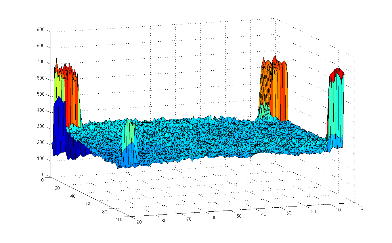
To have a baseline for the sensor before any mods I wrote a quick script to check the bed level + sensor readings
(be kind this is my first ever python program!!)
It basically homes the printer, then moves Z to the sensor Ref height at the home position
and takes a reading on every 2mm square across the bed outputting a CSV list of
X,Y,Reading.
Putting the data into Matlab gives the attached plot, you can see the corner tape
the sensor data is quite consistant which bodes well for the usability if the ambiant light issue
can be sorted.
Chris
|
Re: Improving the proximity sensor - SUCCESS! January 03, 2014 02:14PM |
Registered: 12 years ago Posts: 1,611 |
|
Re: Improving the proximity sensor - SUCCESS! January 03, 2014 04:46PM |
Registered: 10 years ago Posts: 300 |
Quote
chriscain
To have a baseline for the sensor before any mods I wrote a quick script to check the bed level + sensor readings
Excellent idea! I'm running it now to check my own readings.
Hehe... how's about turning the X,Y,Z's into a .stl and printing it back onto the bed !?! (maybe not at 1:1)
RS Components Reprap Ormerod No. 481
|
Re: Improving the proximity sensor - SUCCESS! January 03, 2014 06:28PM |
Registered: 10 years ago Posts: 41 |
|
White Tape VS Silver Tape January 04, 2014 04:25PM |
Registered: 10 years ago Posts: 41 |
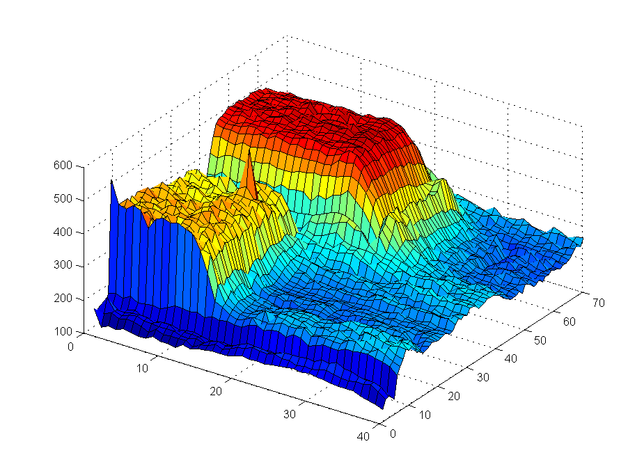
And The winner is......
White Tape
The attached graph shows a square of white tape next to a one of the squares of aluminium tape supplied with the kit
both under a single layer of Kapton Tape.
The sensor was at 3mm, 1 reading every 1mm in X,Y
The nice flat Red area is the white PVC tape
Note not only is the output higher for the PVC but it is significantly more consistant as well.
Most likely reason is the aluminium tape is providing specular reflection and readings depend on exact sensor alignment to surface of tape, the white tape provides a diffuse reflection, which averages giving a more consistant result.
I also tried just a square of laser printer paper under kapton tape, this worked as well as the PVC white tape, in fact I could not see any difference, only reason for using the PVC tape rather than 4 small squares of paper under the Kapton tape is that I apply the Kapton tape using the 'Wet' Method, and this is not easy with bits of paper.
In summary, the silver aluminium tape is not only not required, it is actually WORSE than a bit of paper, and increases the variability of Z homing.
Chris
|
Re: White Tape VS Silver Tape January 04, 2014 04:34PM |
Registered: 10 years ago Posts: 314 |
@chriscain, great piece of work, many thanks for sharing. White tape it is!
Interesting findings about the silver vs white, in a totally different area of 'bathroom heated towel rails', a white version radiates far more infra red than a chrome one for the same power! Just thought I'd mention it....
Ormerod #007 (shaken but not stirred!)
Interesting findings about the silver vs white, in a totally different area of 'bathroom heated towel rails', a white version radiates far more infra red than a chrome one for the same power! Just thought I'd mention it....
Ormerod #007 (shaken but not stirred!)
|
Re: Improving the proximity sensor - SUCCESS! January 05, 2014 07:41AM |
Registered: 10 years ago Posts: 300 |
I found it useful to switch off debug messages by addding the line:
So this is my reference plot using silver foil:
I'm amazed at how the tiny Kapton tape gaps stand out! It's not like they're even as big as 0.1mm
RS Components Reprap Ormerod No. 481
ser.write('M111 S0\n')
So this is my reference plot using silver foil:

I'm amazed at how the tiny Kapton tape gaps stand out! It's not like they're even as big as 0.1mm
RS Components Reprap Ormerod No. 481
Sorry, only registered users may post in this forum.