Duet 3.3V supply quality
Posted by Radian
|
Duet 3.3V supply quality December 27, 2013 11:31AM |
Registered: 10 years ago Posts: 300 |
It seems to me that a good few problems might be attributable to the quality of the Microcontroller supply voltage. I think my Duet board is the latest spec and has an on-board 12V to 5V 2A Buck convertor supplying a 3.3V LDO regulator. The problems I suffer from are *all* intermittent ones such as a random inability to log-in over the network and sudden "all stop" crashes in the middle of printing. Early on I found that things seemed to be more reliable if I connected Duet to my PC via an externally powered USB hub but it did not entirely solve my issues.
The +12V supply from the ATX PSU is not something I trust entirely, and from a quick glance at the Duet schematic, the only bulk capacitance on the output of the 5V reg. is a single 100uF (plus 20uF worth of ceramic caps). Assuming peak currents from the micro in the order of 0.5A, if the 12V dips even for just one millisecond then the micro will not be happy.
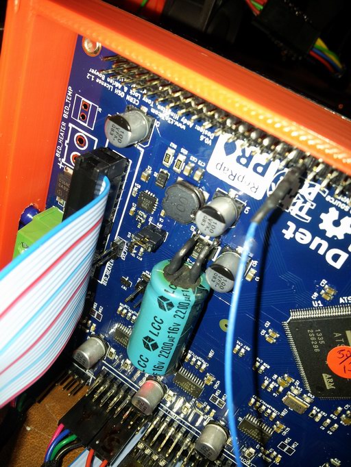
To me, this doesn't seem like anywhere near enough bulk capacitance given the large amounts of current being switched around in motors and heaters on the (relatively crudely regulated) 12V side. So as an experiment, given that it has consistently failed part-way through a particularly long print run three times in succession (stopping at different places each time), I soldered a leaded 2200uF 16V capacitor with a measured ESR of 48 milliohms across the 0V and 5V legs of the 3.3V regulator. If that doesn't sort it - I'll consider my theory busted. So far though, so good... although I still have to press the reset button before I can get a network connection (a power-up reset might be necessary - especially since this extra capacitance will slow the 3.3V rise-time)
RS Components Reprap Ormerod No. 481
The +12V supply from the ATX PSU is not something I trust entirely, and from a quick glance at the Duet schematic, the only bulk capacitance on the output of the 5V reg. is a single 100uF (plus 20uF worth of ceramic caps). Assuming peak currents from the micro in the order of 0.5A, if the 12V dips even for just one millisecond then the micro will not be happy.
To me, this doesn't seem like anywhere near enough bulk capacitance given the large amounts of current being switched around in motors and heaters on the (relatively crudely regulated) 12V side. So as an experiment, given that it has consistently failed part-way through a particularly long print run three times in succession (stopping at different places each time), I soldered a leaded 2200uF 16V capacitor with a measured ESR of 48 milliohms across the 0V and 5V legs of the 3.3V regulator. If that doesn't sort it - I'll consider my theory busted. So far though, so good... although I still have to press the reset button before I can get a network connection (a power-up reset might be necessary - especially since this extra capacitance will slow the 3.3V rise-time)
RS Components Reprap Ormerod No. 481
|
Re: Duet 3.3V supply quality December 27, 2013 11:46AM |
Registered: 12 years ago Posts: 1,611 |
|
Re: Duet 3.3V supply quality December 27, 2013 11:49AM |
Registered: 10 years ago Posts: 135 |
Hi 57.3 Dgrees
The ATX A-550BR supplied with the Ormerod is the cheaest of the cheap 10.50 plus VAT. I suppose they must cut corners somwhere, you could pay that for the fan (RS). Certainly amongst the PC snobs that inhabit fora they have an unenviable reputation. Let us hope your mod does the trick, I am standing by with juicy cap and baited breath.
Rory
Edited 1 time(s). Last edit at 12/27/2013 11:50AM by Rory166.
|
Re: Duet 3.3V supply quality December 27, 2013 12:06PM |
Registered: 10 years ago Posts: 300 |
I'm going to call this a success now. I've been printing all day, and finally got through the long job for the first time without a hitch. One clue I had was when I noticed the temperature readings in the web control panel glitch - the A/D readings appear to be particularly sensitive to the 3.3V rail. What's the betting the dev. team use a more upmarket ATX supply and never notices this problem ;-) Or perhaps even use the 5V ATX feed instead?
I'm rather leaning towards buying one of those "modular" ATX supplies that can have all the disc drive danglies unplugged. I like the idea of running off of 12V and regulating 5V locally - just in case the lights go out again ;-)
Anyway, in the meantime, the capacitor is staying.
Edited 1 time(s). Last edit at 12/27/2013 12:25PM by Radian.
RS Components Reprap Ormerod No. 481
I'm rather leaning towards buying one of those "modular" ATX supplies that can have all the disc drive danglies unplugged. I like the idea of running off of 12V and regulating 5V locally - just in case the lights go out again ;-)
Anyway, in the meantime, the capacitor is staying.

Edited 1 time(s). Last edit at 12/27/2013 12:25PM by Radian.
RS Components Reprap Ormerod No. 481
|
Re: Duet 3.3V supply quality December 27, 2013 12:51PM |
Registered: 12 years ago Posts: 1,611 |
@Radian: We've been using the standard PSUs we ship, though Adrian I think has one of our Mendel 12V PSUs rigged up. We generally use the onboard 5V regulator. It's possible to use the PSU 5V supply; you need to put three header pins in the Duet board next to the 12V header, and rig a wire between them and the header on the ATX power PCB. You'll still need to jumper the middle pin, to force the PSU to turn on.
Ian
RepRapPro tech support
Ian
RepRapPro tech support
|
Re: Duet 3.3V supply quality December 27, 2013 01:14PM |
Registered: 10 years ago Posts: 103 |
|
Re: Duet 3.3V supply quality December 27, 2013 01:18PM |
Registered: 10 years ago Posts: 14,672 |
Radian, that's very interesting! One other thing I notice is that the Duet implementation of the A4403 5V regulator circuit omits the capacitor in parallel with the feedback resistor. Although the datasheet says this is an optional component, without it the transient response is worse, and the feedback input of the IC is more susceptible to noise pickup (e.g. if any of the stepper motor cables go near it). I might try to piggyback a 10nF capacitor on top of R60.
|
Re: Duet 3.3V supply quality December 27, 2013 01:34PM |
Registered: 10 years ago Posts: 135 |
Hey Radian Im a Superfan
Apologies for lack of focus but you get the idea.
In what kind of mad world would you ignore a 5v supply and generate it from the stepping 12v rail? I thought the standby 5v supply was used to power the duet? There is an unused 5v power header position on the Duet board I read somewhere that Think Print direct boards use this?
Rory
PS whilst I was fiddling with my cameraphone I see Ian has answered this, you can run a wire from the header to the 5v standby on the Power conector board. The middle pin is labeled PS_ON which implies that in some use the Duet is capable of controlling the power supply, this could be useful in an emergency it's all gone horibly wrong sort of scenario. Heater temp running away, stepper contoller failed etc etc. Of course the 5v standby remains on. Not quite sure how you contol whether the onboard reg or the psu supply the power? 5V_EN link looks a likely candidate.
Edited 3 time(s). Last edit at 12/27/2013 02:22PM by Rory166.
|
Re: Duet 3.3V supply quality December 27, 2013 01:53PM |
Registered: 10 years ago Posts: 14,672 |
I've been thinking about this a little more:
1. Adding extra capacitance to the output of a switching regulator should be done with care. From the A4403 datasheet:
2. The switching frequency of the A4403 is high, so it should be able to react to changes in load very quickly, even more so if capacitor C6 is added.
3. There are some heavy loads on the 12V supply, especially the bed heater and the extruder heater (I think I metered one at 3 ohms, so 4A current draw). When these heaters switch on and off, there are likely to be some hefty transients on the 12V rail.
So maybe it is the 12V rail that most needs more capacitance, along with the addition of C6 in the regulator circuit as I mentioned in my previous post?
Edited 1 time(s). Last edit at 12/27/2013 01:53PM by dc42.
1. Adding extra capacitance to the output of a switching regulator should be done with care. From the A4403 datasheet:
Quote
The output capacitor determines the output voltage ripple and is used to close the control loop. As outlined in the Control Loop section, the bandwidth has been optimized for an output capacitance of 20 μF. If a particular application requires an extremely low output voltage, the output capacitor can be increased. Any increase will tend to reduce the bandwidth and therefore compromise the transient response performance. In general the output capacitance should not exceed 1000 μF or be less than 10 μF, as this may cause a loop instability to occur.
2. The switching frequency of the A4403 is high, so it should be able to react to changes in load very quickly, even more so if capacitor C6 is added.
3. There are some heavy loads on the 12V supply, especially the bed heater and the extruder heater (I think I metered one at 3 ohms, so 4A current draw). When these heaters switch on and off, there are likely to be some hefty transients on the 12V rail.
So maybe it is the 12V rail that most needs more capacitance, along with the addition of C6 in the regulator circuit as I mentioned in my previous post?
Edited 1 time(s). Last edit at 12/27/2013 01:53PM by dc42.
|
Re: Duet 3.3V supply quality December 27, 2013 02:09PM |
Registered: 10 years ago Posts: 135 |
Hi DC
Seems I may have been a little too quick draw with the old soldering Iron. I like Ian's post above which I only read after fitting the cap. Feed the 5v rail from a 5v output of the psu. Let the poor old 12v take a right bashing from the switching transients. For that matter the psu also produces up to 30A of 3.3V so why not use that ?
Rory
Edited 2 time(s). Last edit at 12/27/2013 02:43PM by Rory166.
|
Re: Duet 3.3V supply quality December 27, 2013 03:16PM |
Registered: 12 years ago Posts: 1,611 |
The design of the power supply on the Duet is to allow for options. I think there was an early design decision to make 12V supply standard, as then there is flexibility. If you specify that power can only come from and ATX PSU, that doesn't necessarily allow for broad uptake. I believe there are other problems connecting the rails of an ATX PSU to the board, probably revolving around the amount of current an ATX PSU can supply on the 5V (30A) and 3.3V (20A, with the supplied PSU) rails, when modulating such small amounts of current that we need, but I may be talking out of my... hat.
@arnaud31: There are 3 holes next to the green 12V PSU screw terminals, labelled 5V_IN, PS_ON, and GND. If you solder pin headers (or screw terminals) into these, you can feed 5V from the ATX PSU into the 2 outer pins. Move the jumper from JP9 (5V_EN) to JP10 (ATX_5V_EN).
The ATX power PCB has 5V output; it's on the pin header, with the jumper. The pin closest to the LEDs is +5V, the furthest is GND. The centre pin will also need to be grounded (as it is with the jumper in place), as this is the PSU enable line. We plan to update the firmware to use this pin to turn the PSU off and on, in future.
Ian
RepRapPro tech support
|
Re: Duet 3.3V supply quality December 27, 2013 04:04PM |
Registered: 10 years ago Posts: 14,672 |
Quote
Rory166
I like Ian's post above which I only read after fitting the cap. Feed the 5v rail from a 5v output of the psu. Let the poor old 12v take a right bashing from the switching transients. For that matter the psu also produces up to 30A of 3.3V so why not use that ?
I like the current scheme of deriving the 3.3V supply via a linear regulator from a 5V supply. A linear regulator can provide a better-regulated supply than a switching one, which is important because the 3.3V supply is being used for the analog reference and is feeding the thermistors and IR sensor.
I can't see any reason in principle against deriving the 5V supply from the 12V supply via an on-board switching regulator, provided that the board is laid out such that the ground current from the A4982 driver chips and heater drive mosfets doesn't interfere with the regulator. I prefer to run it that way unless it causes problems. I've only had one hang so far, at that was right at the end of the print; so I am more inclined to suspect the firmware than the hardware. But if I start to suspect the quality of the power, then I might try using the 5V ATX supply. I'm going to add that capacitor in parallel with R60.
I recall that another member of the RepRap printer family used a 19V laptop power supply. This is a much neater arrangement than the ATX supply. I wonder why the same arrangement wasn't used for the Ormerod (not enough power perhaps?).
What I'd really like to do is modify the firmware to use a time triggered architecture, or at least run the ADC on a timed schedule. Then it would be easy to have the ADC sample the supply voltages at frequent intervals, so that it can report on quality of the supply.
|
Re: Duet 3.3V supply quality December 27, 2013 05:03PM |
Registered: 10 years ago Posts: 300 |
Sure, but the regulator sees a pretty constant load and is "finessed" down to 3.3 by the LDO. I was shooting for around 1000uF with low ESR and 2200uF was the nearest thing I had to hand. I checked the 5V ripple with a scope and it's below 70mV - still, there's certainly more than one way to skin this cat.Quote
dc42
I've been thinking about this a little more:
1. Adding extra capacitance to the output of a switching regulator should be done with care. From the A4403 datasheet:
Quote
The output capacitor determines the output voltage ripple and is used to close the control loop. As outlined in the Control Loop section, the bandwidth has been optimized for an output capacitance of 20 μF. If a particular application requires an extremely low output voltage, the output capacitor can be increased. Any increase will tend to reduce the bandwidth and therefore compromise the transient response performance. In general the output capacitance should not exceed 1000 μF or be less than 10 μF, as this may cause a loop instability to occur.
Yes but of course it can't supply volts that go missing at the input. Both 100uF caps discharge in around 1 to 2mS then it's all over. I have yet to catch it in the act but I suspect the PSU goes offline for a a few cyces now and then. It seems to be a very slow switcher.Quote
dc42
2. The switching frequency of the A4403 is high, so it should be able to react to changes in load very quickly, even more so if capacitor C6 is added.
I get a feeling it's a fair bit more than that. I can see 500mV of ripple @ 1KHz on the 12V. The amount of current drawn is quite a challenge for the interconnects used. I resorted to using the bootlace ferrules as solder cups and pinched them square to fit the clamp terminals. I suspect this may be an area that others might have to check carefully to avoid volt-drops.Quote
dc42
3. There are some heavy loads on the 12V supply, especially the bed heater and the extruder heater (I think I metered one at 3 ohms, so 4A current draw). When these heaters switch on and off, there are likely to be some hefty transients on the 12V rail.
I heartily agree! The blocking diode D1 will prevent the additional capacitance seeing the 12V loads and the higher working voltage will keep the 5V in regulation for longer for a given capacitance, although a 25V cap may be advisable in this position. Unfortunately, when I looked at doing this originally I couldn't see a neat way of adding a big leaded part to beef-up C3.Quote
dc42
So maybe it is the 12V rail that most needs more capacitance, along with the addition of C6 in the regulator circuit as I mentioned in my previous post?
RS Components Reprap Ormerod No. 481
|
Re: Duet 3.3V supply quality December 27, 2013 05:37PM |
Registered: 10 years ago Posts: 14,672 |
I agree, it doesn't look easy to add a big capacitor in parallel with C3. However, I've found 470uF 25V and 680uF 16V SMD capacitors that will probably fit in the C3 position, and 330uF 16V caps that will definitely fit. I'll add some to my next Farnell order. Or maybe just get an ATX PSU with better resistance to brownouts.
|
Re: Duet 3.3V supply quality December 28, 2013 06:18AM |
Registered: 10 years ago Posts: 300 |
Hi dc42. I think the only real issue/challenge to the PSU may be the bed heater. Triggering a Scope on the rising edge of the BED- (when TR2 switches off) shows the PSU recovery peaking at around 20V for a few hundred nS which is why I'd go for a 25V cap at the input of the regulator. The flyback from the bed inductance hits the breakdown voltage of the Mosfet (about 50V) and rings for a lot longer. This makes it tricky to see the 5v/3.3V rails with so much power sloshing around but I think the original design probably handled things sufficiently well.
So brownouts remain my chief suspect as well - although despite the big problems with the weather recently, it's hard to credit the rate of lock-ups that I was getting before I added the extra capacitance.
RS Components Reprap Ormerod No. 481
So brownouts remain my chief suspect as well - although despite the big problems with the weather recently, it's hard to credit the rate of lock-ups that I was getting before I added the extra capacitance.
RS Components Reprap Ormerod No. 481
|
Re: Duet 3.3V supply quality December 28, 2013 07:57AM |
Registered: 10 years ago Posts: 135 |
Radian
You are way ahead of me. Inductance tends to produce a negative pulse on interruption which is why a freewheel diode is normally used when driving an inductive load. Presumably the stepper drivers have these as a matter of course. Talk of 50V spikes is very worrying so I might suggest a 15V transorb to absorb any positive excursion. The recovery characteristic of this psu seems quite poor which may go someway to explain their unsavory reputation. It's almost tempting to put a stonking 12V sla battery across the 12V rail and say go on power company, cheap psu and inadequate cicuit design - do your worst! Then there would be plenty of time for printing to pause in good order in the event of a power cut. I've been meaning to raise this issue, might start another thread.
Rory
Edited 1 time(s). Last edit at 12/28/2013 07:58AM by Rory166.
|
Re: Duet 3.3V supply quality December 28, 2013 09:08AM |
Registered: 10 years ago Posts: 314 |
As a possibly simpler and easy to implement power supply improvement, how about a USB Y power lead?
With the DUET internal power jumper removed the 12V and 5V/3.3V has a degree of noise and brown out isolation.
A simple USB power adapter can remain connected and powered (ensuring a good 5V's) this will allow the laptop/PC can be disconnected when required without any supply interruption.
example product:
[www.ebay.co.uk]
|
Re: Duet 3.3V supply quality December 28, 2013 09:29AM |
Registered: 10 years ago Posts: 14,672 |
Radian, thanks for the warning about the 20V spike when the bed heater turns off. I haven't looked at my Ormerod with a scope yet. If the 20V spike on the 12V rail only lasts for a few hundred ns, then I suspect it is the result of power circuit inductance rather than the ATX PSU taking a long time to recover. The Duet schematic shows decoupling capacitors on the 12V line near the stepper drivers, but none near either of the heater drivers. Maybe there is room to add some 1uF ceramic capacitors.
If there is a 50V spike on the mosfet drain due to the inductance of the bed, then even though this is probably within the avalanche rating of the mosfet, the two LEDs connected in parallel with the bed heater (one on the bed, the other on the electronics board) will also suffer avalanche breakdown. I'll take a look at mine with a scope, and if I see the same thing then I'll put a flyback diode across the heated bed screw terminals.
btw the led on my heated bed appears to turn on and off abruptly, so I think the PID parameters need some tuning.
Edited 1 time(s). Last edit at 12/28/2013 09:30AM by dc42.
Large delta printer [miscsolutions.wordpress.com], E3D tool changer, Robotdigg SCARA printer, Crane Quad and Ormerod
Disclosure: I design Duet electronics and work on RepRapFirmware, [duet3d.com].
|
Re: Duet 3.3V supply quality December 28, 2013 03:54PM |
Registered: 10 years ago Posts: 300 |
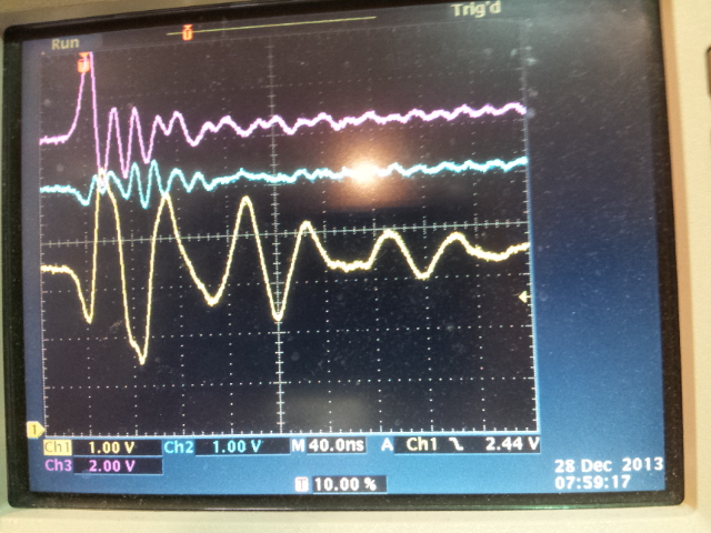
I'd appreciate anyone with a scope confirming my observation of crazy transients on the 3.3V rail. There appears to be a chronic reaction to small transients on the 5V rail. In the scope photo below the blue trace is 5V (measured between pin 1 & 2 on the upper header) and the yellow trace is 3.3V (measured between pin 3 & 2 on the same header). The Duet board is just connected to a Samsung phone charger (to eliminate as much as possible) and the spike is repeatably generated by almost any mains switch (e.g. nearby soldering iron in this case).
What really gets me is how the tiniest glitch on the 5V rail (this is the highest supply voltage in the sytem I'm testing remember) rings for a few uS to well over 10V on the 3.3V rail. Surely this has to be stored magnetically somewhere on the output side of the 3.3V regulator - with L2~L6 being the only potential candidates? Not only that but it all takes place across C11 - a 22uF ceramic which I couldn't beleive - so I applied the scope probe and ground across the cap and could still see the same kind of transients. Amazing. Watching the 3.3V rail whether printing or not, it looks a right mess on my board so no wonder the micro hangs regularly.
This second photo shows the small transient on the 12V rail (magenta trace) from the heated bed flyback working its way through the 5V and then 3.3V rails when powered from a 12V 25A bench supply. Of course this is happening all the time during a print.
Edited 2 time(s). Last edit at 12/28/2013 03:59PM by Radian.
RS Components Reprap Ormerod No. 481

What really gets me is how the tiniest glitch on the 5V rail (this is the highest supply voltage in the sytem I'm testing remember) rings for a few uS to well over 10V on the 3.3V rail. Surely this has to be stored magnetically somewhere on the output side of the 3.3V regulator - with L2~L6 being the only potential candidates? Not only that but it all takes place across C11 - a 22uF ceramic which I couldn't beleive - so I applied the scope probe and ground across the cap and could still see the same kind of transients. Amazing. Watching the 3.3V rail whether printing or not, it looks a right mess on my board so no wonder the micro hangs regularly.
This second photo shows the small transient on the 12V rail (magenta trace) from the heated bed flyback working its way through the 5V and then 3.3V rails when powered from a 12V 25A bench supply. Of course this is happening all the time during a print.

Edited 2 time(s). Last edit at 12/28/2013 03:59PM by Radian.
RS Components Reprap Ormerod No. 481
|
Re: Duet 3.3V supply quality December 28, 2013 04:30PM |
Registered: 10 years ago Posts: 256 |
Dunno if its related and apologise if this is just noise in this thread or simply explainable, but heres a "fun" thing. ( NB there is no power applied to the board anywhere during this experiment) If, with all wiring and everything else (except the atx psu) connected, I wind the z-axis rod fast by hand either up or down, the extruder fan rotates at a good speed. (Hey I'm generating 12volts somehow!) However if I disconnect the z-motor connector at the board and do the same thing I get no rotation whatsoever from the extruder fan.
Bear in mind I havent verified my connections yet. I'll check everything but it seems that The Ormerod is quite a good dynamo?
regards
Andy
Edited 1 time(s). Last edit at 12/28/2013 04:30PM by kwikius.
Bear in mind I havent verified my connections yet. I'll check everything but it seems that The Ormerod is quite a good dynamo?
regards
Andy
Edited 1 time(s). Last edit at 12/28/2013 04:30PM by kwikius.
|
Re: Duet 3.3V supply quality December 28, 2013 04:39PM |
Registered: 10 years ago Posts: 300 |
Not Dynamo, but Alternator I think you'll findQuote
kwikius
Dunno if its related and apologise if this is just noise in this thread or simply explainable, but heres a "fun" thing. ( NB there is no power applied to the board anywhere during this experiment) If, with all wiring and everything else (except the atx psu) connected, I wind the z-axis rod fast by hand either up or down, the extruder fan rotates at a good speed. (Hey I'm generating 12volts somehow!) However if I disconnect the z-motor connector at the board and do the same thing I get no rotation whatsoever from the extruder fan.
Bear in mind I havent verified my connections yet. I'll check everything but it seems that The Ormerod is quite a good dynamo?
regards
Andy

Er, yes AC - so something semiconducting is doing the rectifying - probably under duress so I'd stop that now if I were you

RS Components Reprap Ormerod No. 481
|
Re: Duet 3.3V supply quality December 28, 2013 04:41PM |
Registered: 12 years ago Posts: 1,611 |
@Radian: thanks for your continued detective work. It would be good to get someone else to verify this, just in case it's a fault with your board.
Some points:
The bed control is bang-bang, not PWM, as far as I know. People have implemented PWM for heated beds in Marlin, but I'm not sure of the effect on the life of the MOSFETs of switching 12V at around 10A fast. It's within their specification to cope, but I've heard of burnout problems on RAMPS boards doing this. The bed resistance is around 1.3 ohms, so at 12V should draw around 9A.
I think in this thread someone suggested using a 19V laptop PSU. We supply one of these with our Huxley kit, but it can only supply around 6A. This is okay for the small bed of the Huxley, but not for a Mendel bed with a resistance of around 1.3 ohms - it would draw 19V x 1.3 ohms = 14.6A.
The Duet board can, apparently (and not something we've tested), cope with up to 35V input.
I'm not competent to answer questions at the level you guys need answers, so I'll forward any responses on to Adrian Bowyer, and get him to read this thread, too. Hopefully, Tony at Think3DPrint3D can also get involved.
Ian
RepRapPro tech support
Edited 1 time(s). Last edit at 12/28/2013 04:42PM by droftarts.
|
Re: Duet 3.3V supply quality December 28, 2013 04:43PM |
Registered: 10 years ago Posts: 135 |
Radian
I would like to examine the circuit diagram of the duet but am unable to access through github, possibly due to my use of a Mac. Are you able to direct me to a copy? I need this to use my scope on the board to confirm your results are universal.
Rory
Edited 1 time(s). Last edit at 12/28/2013 05:29PM by Rory166.
|
Re: Duet 3.3V supply quality December 28, 2013 04:52PM |
Registered: 10 years ago Posts: 300 |
Quote
droftarts
@Radian: thanks for your continued detective work. It would be good to get someone else to verify this, just in case it's a fault with your board.
Yes, agreed - this could be something peculiar to my own controller. Many others have printed without problems.
PM sent Rory.
RS Components Reprap Ormerod No. 481
|
Re: Duet 3.3V supply quality December 28, 2013 05:07PM |
Registered: 10 years ago Posts: 14,672 |
Quote
Rory166
I would like to examine the circuit diagram of the duet but am unable to access through github, possibly due to my use of a Mac. Are you able to direct me to a copy? I need this to use my scope onth eboard to confirm your results are universal.
Rory, if you PM me your email address, I'll email you the pdf.
Large delta printer [miscsolutions.wordpress.com], E3D tool changer, Robotdigg SCARA printer, Crane Quad and Ormerod
Disclosure: I design Duet electronics and work on RepRapFirmware, [duet3d.com].
|
Re: Duet 3.3V supply quality December 28, 2013 05:17PM |
Registered: 12 years ago Posts: 1,236 |
With those sort of transients, I am surprised it works as long as it does... that said I better have a look at my own design!
RAMPS has a number of "burnout" problems, which is partly why I am trying design a better one. PWM works fine with the right MOSFETs and drivers, but obviously makes transients worse. Bang-bang is just very slow PWM.
What is Open Source?
What is Open Source Hardware?
Open Source in a nutshell: the Four Freedoms
CC BY-NC is not an Open Source license
|
Re: Duet 3.3V supply quality December 28, 2013 05:27PM |
Registered: 10 years ago Posts: 300 |
Quote
bobc
With those sort of transients, I am surprised it works as long as it does... that said I better have a look at my own design!
If you look at the timebase you'll see that they're pretty fast. Probably that's how the micro manages. I still can't figure why it's so sensitive to mains-borne noise though and that stuff seems to be more spread-out and hence more problematic.
RS Components Reprap Ormerod No. 481
|
Re: Duet 3.3V supply quality December 28, 2013 05:40PM |
Registered: 10 years ago Posts: 14,672 |
Radian, I attached a scope to my Duet board to see if I can replicate your observations. This is what I found on the mosfet drain:
As you say, there is a 50V spike and the mosfet is avalanching. Here is the voltage on the 12V input, measure directly between the screw terminals:
I don't see a 20V spike, the peak is a little under 14V. I did see a bigger spike when I connected the scope earth probe to one of the earth pins next to the motor outputs instead of holding the earth clip against the negative screw terminal.
I then made a few mods to my Duet board. I added a 470uF 25V capacitor in parallel with C3 to increase the length of 12V supply brownout that the 5V regulator can tolerate. I piggybacked a 10nF capacitor across R60, as recommended on the A4403 datasheet to improve the transient response of the regulator. I connected a flyback diode across the holes for a screw terminal connector for the bed heater - I used a UF4003 which was to hand and can tolerate a 30A peak surge for 8ms, so should have no trouble handling 11A for a few microseconds. [EDIT: I think the flyback diode is probably a waste of time, instead it would be better to slow down the mosfet turn-off as suggested by bobc later in this thread.]
On the underside, I connected a 1uF ceramic decoupling capacitor between bed heater +ve supply and 12V in negative terminal, which was the nearest I could get to the mosfet source pin. This was an attempt to make up in part for the lack of any decoupling capacitors for the bed heater circuit in the Duet electronics. Why they decoupled the 800mA stepper motor supplies yet didn't decouple the 11A bed heater supply defies explanation.
I also soldered 2 of the tabs on the USB connector that were not already soldered (the other 2 were OK).
I then remeasured the signal at the mosfet drain when the bed heater turns off:
The 50V spike is down to 35V because of the flyback diode and the avalanching is gone, although there is some ringing at about 20MHz. Either the flyback diode is not fast enough, or the inductance in the traces between the diode and the bed heater is the problem. A Schottky diode connected directly between the ribbon cable connector terminals on the underside of the board would be better.
I then looked at the 12V supply again:
No improvement there, in fact there appears to be some more high-frequency ringing. But a 1uF capacitor isn't what I really want here, I would prefer something like 0.1uF ceramic in parallel with 1000uF electrolytic.
I'll take a look at the 3.3V rail next.
Edited 3 time(s). Last edit at 12/29/2013 03:29AM by dc42.
Large delta printer [miscsolutions.wordpress.com], E3D tool changer, Robotdigg SCARA printer, Crane Quad and Ormerod
Disclosure: I design Duet electronics and work on RepRapFirmware, [duet3d.com].

As you say, there is a 50V spike and the mosfet is avalanching. Here is the voltage on the 12V input, measure directly between the screw terminals:

I don't see a 20V spike, the peak is a little under 14V. I did see a bigger spike when I connected the scope earth probe to one of the earth pins next to the motor outputs instead of holding the earth clip against the negative screw terminal.
I then made a few mods to my Duet board. I added a 470uF 25V capacitor in parallel with C3 to increase the length of 12V supply brownout that the 5V regulator can tolerate. I piggybacked a 10nF capacitor across R60, as recommended on the A4403 datasheet to improve the transient response of the regulator. I connected a flyback diode across the holes for a screw terminal connector for the bed heater - I used a UF4003 which was to hand and can tolerate a 30A peak surge for 8ms, so should have no trouble handling 11A for a few microseconds. [EDIT: I think the flyback diode is probably a waste of time, instead it would be better to slow down the mosfet turn-off as suggested by bobc later in this thread.]

On the underside, I connected a 1uF ceramic decoupling capacitor between bed heater +ve supply and 12V in negative terminal, which was the nearest I could get to the mosfet source pin. This was an attempt to make up in part for the lack of any decoupling capacitors for the bed heater circuit in the Duet electronics. Why they decoupled the 800mA stepper motor supplies yet didn't decouple the 11A bed heater supply defies explanation.

I also soldered 2 of the tabs on the USB connector that were not already soldered (the other 2 were OK).
I then remeasured the signal at the mosfet drain when the bed heater turns off:

The 50V spike is down to 35V because of the flyback diode and the avalanching is gone, although there is some ringing at about 20MHz. Either the flyback diode is not fast enough, or the inductance in the traces between the diode and the bed heater is the problem. A Schottky diode connected directly between the ribbon cable connector terminals on the underside of the board would be better.
I then looked at the 12V supply again:

No improvement there, in fact there appears to be some more high-frequency ringing. But a 1uF capacitor isn't what I really want here, I would prefer something like 0.1uF ceramic in parallel with 1000uF electrolytic.
I'll take a look at the 3.3V rail next.
Edited 3 time(s). Last edit at 12/29/2013 03:29AM by dc42.
Large delta printer [miscsolutions.wordpress.com], E3D tool changer, Robotdigg SCARA printer, Crane Quad and Ormerod
Disclosure: I design Duet electronics and work on RepRapFirmware, [duet3d.com].
|
Re: Duet 3.3V supply quality December 28, 2013 05:57PM |
Registered: 12 years ago Posts: 1,236 |
Quote
dc42
Radian, I attached a scope to my Duet board to see if I can replicate your observations. This is what I found on the mosfet drain:
Ha, just realised that selling a product on RS means there will be many EE types inspecting the design..
But this is all very interesting... I have a similar screen shot taken recently, but on RAMPS-FD:

I see that Duet uses a similar design for the gate driver I used, the small MOSFET causes a fast turn off on the big MOSFET. I only just start looking in detail at the gate driver behaviour. For various reasons we have decided to change that method in RAMPS-FD, mainly in order to get a faster turn on time. As it happens the new method will have a gentler turn on/off.
Although I dabble with digital electronics, the rest is a bit of a black art to me, so I am looking to pick up some tips!
ETA: fix link
Edited 1 time(s). Last edit at 12/29/2013 10:18AM by bobc.
What is Open Source?
What is Open Source Hardware?
Open Source in a nutshell: the Four Freedoms
CC BY-NC is not an Open Source license
|
Re: Duet 3.3V supply quality December 28, 2013 06:04PM |
Registered: 10 years ago Posts: 14,672 |
Here are my photos of the 5V and 3.3V supplies when the bed heater is turned off (yellow trace is 5V or 3.3V, blue trace is mosfet drain voltage which I used to trigger the scope):
This is after I did the mods I listed in my previous post. The 5V and 3.3V transients are not very different, so I believe they are mostly caused either by the scope probe and its earth lead detecting the magnetic field induced when the bed heater current is turned off, or are ground plane noise caused by the bed heater current turning off abruptly.
Edited 2 time(s). Last edit at 12/29/2013 03:22AM by dc42.
Large delta printer [miscsolutions.wordpress.com], E3D tool changer, Robotdigg SCARA printer, Crane Quad and Ormerod
Disclosure: I design Duet electronics and work on RepRapFirmware, [duet3d.com].

Sorry, only registered users may post in this forum.