Head sagging again
Posted by dc42
|
Head sagging again December 31, 2013 03:44AM |
Registered: 10 years ago Posts: 14,672 |
My print head started sagging again, throwing out the z-probe calibration. This time, it wasn't the x-runner causing the problem. What had happened was that the 2 screws securing the nozzle to the nozzle mount were no longer as tight as they used to be. I suspect that the heat conducted from the hot end through the screws had softened the plastic. Also, the cap-head screws don't sit in the middle of the countersunk holes.
Should I try using countersunk screws to secure the hot end to the nozzle mount, or is a redesign of the nozzle mount required?
Large delta printer [miscsolutions.wordpress.com], E3D tool changer, Robotdigg SCARA printer, Crane Quad and Ormerod
Disclosure: I design Duet electronics and work on RepRapFirmware, [duet3d.com].
|
Re: Head sagging again December 31, 2013 05:53AM |
Registered: 10 years ago Posts: 1,230 |
Open sided countersunk holes + softened plastic = move to the side
a cap head screw with a washer under, larger than the coundersunk cavity would be better imho
..or better, instead of the washers, make a copy of the MDF heat insulator in steel an put in under the screws
Edited 1 time(s). Last edit at 12/31/2013 06:25AM by ormerod168.
a cap head screw with a washer under, larger than the coundersunk cavity would be better imho
..or better, instead of the washers, make a copy of the MDF heat insulator in steel an put in under the screws
Edited 1 time(s). Last edit at 12/31/2013 06:25AM by ormerod168.
|
Re: Head sagging again December 31, 2013 05:56AM |
Registered: 10 years ago Posts: 256 |
Quote
ormerod168
Open sided countersunk holes + softened plastic = move to the side
a cap head screw with a washer under, larger than the coundersunk cavety would be better imho
..or better, instead of the washers, make a copy of the MDF heat insulator in steel an put in under the screws
Yes! .. was going to suggest 12 mm ally angle as a better heattsink (think they have it in B&Q)
regards
Andy
Ormerod #318
www.zoomworks.org - Free and Open Source Stuff

|
Re: Head sagging again December 31, 2013 06:38AM |
Registered: 10 years ago Posts: 1,230 |
If the heat from the aluminium cooling block is a problem for the plastic, then the same could be said for the screws, heat move to top through the screws
the aluminium cooling block is isolated from the plastic by the MDF heat insulator, screws not
As I am a bit from printing myself I do not know if this is a problem at all if heat sink compound is added between the alu block and the cooling block
Documentation says: "...If you have it you can put a little heatsink compound..."
Edited 1 time(s). Last edit at 12/31/2013 06:38AM by ormerod168.
|
Re: Head sagging again December 31, 2013 07:03AM |
Registered: 10 years ago Posts: 256 |
Quote
ormerod168
If the heat from the aluminium cooling block is a problem for the plastic, then the same could be said for the screws, heat move to top through the screws
the aluminium cooling block is isolated from the plastic by the MDF heat insulator, screws not
[...]
The idea was to put the angle so It sits on top of the plastic where the screws are. Butt the upright part of the angle against the fan heatsink. Drill holes ( and maybe slots) for the screws to go through. The fan heatsink is quite cool at that point (from experiment with head at 200 deg c) so the ally angle should work well there. Add heatsink compound if you have it.
(Not tested!)
As an aside... Its probably best to turn the heater off and let the fan run for several minutes until the head cools down since without the fan on, the screws will start to get hotter!
These might be of interest too.. say they have a coontinous working temp of 250 deg c
High temperature plastic screws
regards
Andy
Edited 2 time(s). Last edit at 12/31/2013 07:22AM by kwikius.
Ormerod #318
www.zoomworks.org - Free and Open Source Stuff
|
Re: Head sagging again December 31, 2013 07:51AM |
Registered: 10 years ago Posts: 14,672 |
Quote
ormerod168
As I am a bit from printing myself I do not know if this is a problem at all if heat sink compound is added between the alu block and the cooling block
Documentation says: "...If you have it you can put a little heatsink compound..."
I had some Arctic Silver, so I used that.
Quote
kwikius
As an aside... Its probably best to turn the heater off and let the fan run for several minutes until the head cools down since without the fan on, the screws will start to get hotter!
Yes, I always do that.
Large delta printer [miscsolutions.wordpress.com], E3D tool changer, Robotdigg SCARA printer, Crane Quad and Ormerod
Disclosure: I design Duet electronics and work on RepRapFirmware, [duet3d.com].
|
Re: Head sagging again December 31, 2013 08:37AM |
Registered: 10 years ago Posts: 27 |
Hi,
I've had the same sagging head problem.
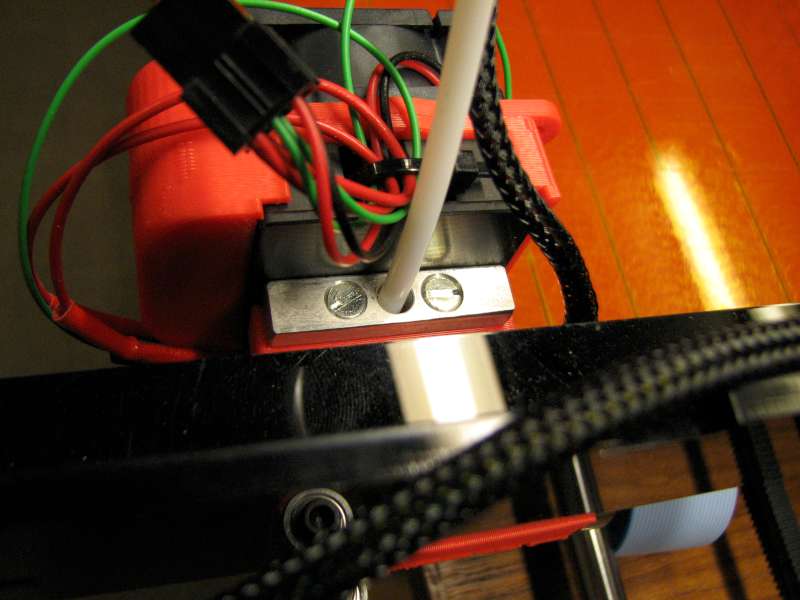
My fan seems to be slow and needs a nudge to get it spinning - a pain when I'm constantly resetting the board and turning off the ATX power - and then forget to set it spinning again. The other day I did just that and the head started to sag really bad. Whilst the nozzle mount was still soft I added a M3 washer under each head, see photo.
However it still starts to sag after an hour or so. I'm going to redesign the mounting - it just needs to be a couple of mm deeper, the two slots closed off and the countersink removed. Or has anyone else already done this?
Regards,
Simon
RS Ormerod No 192
I've had the same sagging head problem.
My fan seems to be slow and needs a nudge to get it spinning - a pain when I'm constantly resetting the board and turning off the ATX power - and then forget to set it spinning again. The other day I did just that and the head started to sag really bad. Whilst the nozzle mount was still soft I added a M3 washer under each head, see photo.

However it still starts to sag after an hour or so. I'm going to redesign the mounting - it just needs to be a couple of mm deeper, the two slots closed off and the countersink removed. Or has anyone else already done this?
Regards,
Simon
RS Ormerod No 192
|
Re: Head sagging again December 31, 2013 09:03AM |
Registered: 10 years ago Posts: 1,230 |
Hi Simon
Great picture, shows your problem very well!, no the washers don't help much, better to go with my idea or Andy's alu angle idea or redesign it me think
..or better, instead of the washers, make a copy of the MDF heat insulator in (2-3mm) steel (or alu) and put in under the screws
...and you could make it a bit wider than the MDF bit, would help cooling the screws...and a bit longer and bend up the ends, would ad to the cooling too
|
Re: Head sagging again December 31, 2013 09:25AM |
Registered: 10 years ago Posts: 1,230 |
Quote
Andy
The idea was to put the angle so It sits on top of the plastic where the screws are. Butt the upright part of the angle against the fan heatsink. Drill holes ( and maybe slots) for the screws to go through. The fan heatsink is quite cool at that point (from experiment with head at 200 deg c) so the ally angle should work well there. Add heatsink compound if you have it.
Andy
..and even better if one could mount it to the heatsink with screws, that would make the whole system more stable...but then you would get no leverage on the plastic part, so the holes would have to be slots and tightened last, that would be a bit tricky, not much space there
|
Re: Head sagging again December 31, 2013 10:18AM |
Registered: 10 years ago Posts: 27 |
One other issue that I forgot to mention is that the problem is made worse by the Bowden tube. As the X carriage moves back and forth the tube tension pushes the print head down. I've just put an elastic band around the Bowden tube which seems to help. I tried cable ties at first but they caused the tube to lift the head when the x-carriage was at both ends of travel.
Hope this helps.
Simon
RS Ormerod No 192

Hope this helps.
Simon
RS Ormerod No 192
|
Re: Head sagging again December 31, 2013 10:37AM |
Registered: 10 years ago Posts: 135 |
Hi All
Can I suggest the following belt braces and suspenders solution. Replica of MDF insulator both in 8mm alu strip and MDF. Redesign the part deeper so the top part above the screw is a reflection of below screws, close the ends of the slots both above and below screws and re print in ABS. Above fit the alu plate and mdf with longer screws and then attach heatsink.
I have asked my design department to redesign the part but currently in the que behind an earlier request.
Rory
|
Re: Head sagging again December 31, 2013 01:40PM |
Registered: 10 years ago Posts: 314 |
@Rorry166 and Ormerod168,
I like your proposals.
I was planning to duplicate the mdf heat insulator and make a sandwich across the printed parts as suggested, i.e with clearance around the screws in the printed part. This plan came about due to the fan not operating with my original build (and the instructions at that time not making this clear that it is always on, or should be!) and I nearly had a total melt down.
The additional alluminium plate will make this even better, so thanks for that idea.
An additional mod I currently have is on each of the bolts I have placed 3 washers between the alluminium block and the heat insulator. This serves two purposes, to add an air gap but more importantly in my case also allow the nozzle to be slightly lower. This later point I found essential to get the required clearance between the z height sensor mount printed part and the extruder tip.
|
Re: Head sagging again December 31, 2013 03:54PM |
Registered: 10 years ago Posts: 135 |
Treth
I like your thinking. In an earlier thread we were discussing how to get 1.5mm minimum Z-sensor to bed clearance. I am now looking at the printed part and thinking "There are forces at work here of which we know nothing"( small prize for the person who spots the origin of this quote). What I am alluding to is the three colour printing head. The design of this part seems to make little sense but are things done to make way for the three heads which we know nothing? I refer to the fact that the screws holding the printed part to the x-carriage have the same spacing as the screws holding the hot end. This makes for all this trouble which seems entirely unnecessary until you try to package two more nozzles right up close. I am assuming that the three air jets are for the three hot ends?
I am wondering whether to replace the printed part with an aluminium version? This could potentially be in two parts with the base fixed with the two csk screws and the bar fixed with 2 more csk screws threaded into the base at a wider spacing.
Rory
Edited 1 time(s). Last edit at 12/31/2013 03:55PM by Rory166.
|
Re: Head sagging again December 31, 2013 05:22PM |
Registered: 10 years ago Posts: 27 |
I agree with these comments - it would be much better to have an aluminium mounting for the extruder head.
As a quick fix I've made a part as discussed earlier - came out OK. You can see from the photos that the fan assembly is still hanging down a bit, but it got really hot when the fan wasn't on
New hot end mounting
The perspective makes it look like the nozzle is higher than the fan shroud - it isn't really!
New mount with M3 washers
Hopefully this mod will work OK for the next few weeks.
Regards,
Simon
RS Ormerod No 192
As a quick fix I've made a part as discussed earlier - came out OK. You can see from the photos that the fan assembly is still hanging down a bit, but it got really hot when the fan wasn't on

New hot end mounting

The perspective makes it look like the nozzle is higher than the fan shroud - it isn't really!

New mount with M3 washers
Hopefully this mod will work OK for the next few weeks.
Regards,
Simon
RS Ormerod No 192
|
Re: Head sagging again December 31, 2013 05:49PM |
Registered: 10 years ago Posts: 135 |
|
Re: Head sagging again December 31, 2013 05:51PM |
Registered: 10 years ago Posts: 14,672 |
Simon, that looks good! Would you care to share the STL file for your new nozzle mount?
Large delta printer [miscsolutions.wordpress.com], E3D tool changer, Robotdigg SCARA printer, Crane Quad and Ormerod
Disclosure: I design Duet electronics and work on RepRapFirmware, [duet3d.com].
Large delta printer [miscsolutions.wordpress.com], E3D tool changer, Robotdigg SCARA printer, Crane Quad and Ormerod
Disclosure: I design Duet electronics and work on RepRapFirmware, [duet3d.com].
|
Re: Head sagging again January 01, 2014 08:21AM |
Registered: 10 years ago Posts: 27 |
Hi,
I've made another mount - 0.5mm smaller than the previous mounting. Fits OK now. I've attached the STL file - see below.
In Slic3r I outputted it with 4 top and bottom layers, 0.5 infill and 2 walls. The finished part weighs approx. double the original.
Maybe that's why it was warping - it's printed with a low infill so it's fairly hollow.
Also, you'll need to open up the screw holes with a 3.0mm drill - two of the holes are closed as I didn't know how to intersect two
cylinders in the 3D modelling software - sorry!
If you print the part almost solid like I did then allow it to cool properly before attempting to pull it off the print surface - about 15-20 minutes.
Hope this helps.
Happy New Printing,
Simon
RS Ormerod No 192
I've made another mount - 0.5mm smaller than the previous mounting. Fits OK now. I've attached the STL file - see below.
In Slic3r I outputted it with 4 top and bottom layers, 0.5 infill and 2 walls. The finished part weighs approx. double the original.
Maybe that's why it was warping - it's printed with a low infill so it's fairly hollow.
Also, you'll need to open up the screw holes with a 3.0mm drill - two of the holes are closed as I didn't know how to intersect two
cylinders in the 3D modelling software - sorry!
If you print the part almost solid like I did then allow it to cool properly before attempting to pull it off the print surface - about 15-20 minutes.

Hope this helps.
Happy New Printing,
Simon
RS Ormerod No 192
|
Re: Head sagging again January 01, 2014 09:39AM |
Registered: 10 years ago Posts: 135 |
|
Re: Head sagging again January 01, 2014 10:20AM |
Registered: 10 years ago Posts: 27 |
Quote
Rory166
Simon
Part looks absolutely brilliant. May I make one further suggestion, if the protruding part was made 1 mm deeper at the bottom face it would enable the head to be a bit lower for the correct operation of the z sensor as per an earlier post.
Rory
Thanks Rory.
I've changed the part so that the head is 0.8mm lower than the IR sensor. I think there should be enough thread left on the M3 screws - I've not tried it yet.

STL file attached.
Still needs drilling!
Regards,
Simon
RS Ormerod No 192
|
Re: Head sagging again January 01, 2014 10:34AM |
Registered: 10 years ago Posts: 14,672 |
Thanks Simon, I'll print a new part just as soon as I have some more filament.
Does anyone know whether the original parts in the kit are ABS or PLA? I don't yet know how to tell the difference, other than by applying acetone.
Large delta printer [miscsolutions.wordpress.com], E3D tool changer, Robotdigg SCARA printer, Crane Quad and Ormerod
Disclosure: I design Duet electronics and work on RepRapFirmware, [duet3d.com].
|
Re: Head sagging again January 01, 2014 10:47AM |
Registered: 10 years ago Posts: 135 |
Simon
I think for safety the sensor should be 1.5mm from the reflective surface as a minimum. Your new design looks even better.
David
I am almost certain that RRP use only PLA from Haberdashery. I think there is a bit of a green agenda here so even if ABS were more suitable for certain parts in will not be used.
Rory
|
Re: Head sagging again January 01, 2014 11:01AM |
Registered: 10 years ago Posts: 14,672 |
Quote
Rory166
I think for safety the sensor should be 1.5mm from the reflective surface as a minimum. Your new design looks even better.
The sensor face is somewhat above the edge of the sensor board. On my unit, this puts the sensor face about 1.5mm above the nozzle already.
Quote
Rory166
I am almost certain that RRP use only PLA from Haberdashery. I think there is a bit of a green agenda here so even if ABS were more suitable for certain parts in will not be used.
Rory
Thanks Rory, I was thinking that printing this particular part in ABS might be advantageous.
Large delta printer [miscsolutions.wordpress.com], E3D tool changer, Robotdigg SCARA printer, Crane Quad and Ormerod
Disclosure: I design Duet electronics and work on RepRapFirmware, [duet3d.com].
|
Re: Head sagging again January 01, 2014 12:43PM |
Registered: 10 years ago Posts: 1,230 |
Quote
... Replica of MDF insulator..
Did, is made of 5mm alu, see the attached pics
..now what to do about the twisted alu bed (0.45mm off, doh)
Erik
|
Re: Head sagging again January 01, 2014 01:12PM |
Registered: 10 years ago Posts: 27 |
I made the mount with the extra 0.8mm - now works perfectly. With the nozzle being lower the sensor is now lifted from the bed to an ideal position.
Here are my new G31 readings:
0.0 868
0.1 841
0.2 802
0.3 778
0.4 750
0.5 702
0.6 669
0.7 628
0.8 592
0.9 568
1.0 551
HTH
Simon
RS Ormerod No 192
Here are my new G31 readings:
0.0 868
0.1 841
0.2 802
0.3 778
0.4 750
0.5 702
0.6 669
0.7 628
0.8 592
0.9 568
1.0 551


HTH
Simon
RS Ormerod No 192
|
Re: Head sagging again January 04, 2014 05:17PM |
Registered: 10 years ago Posts: 2,472 |
Hmmm. As an unscientific test, I've just touched the head of one of the screws in question with my little fingertip during a print. It is just slightly warm to the touch, I estimate maybe 40 deg at the very most, even though I'm 2 hours into an ABS print job (230 deg setting). Certainly the screws are not hot enough to soften the printed part. Maybe the root problem is a failure of the fan at some time, or insufficient heat conductivity to the heatsink?
|
Re: Head sagging again January 05, 2014 11:31AM |
Registered: 10 years ago Posts: 14,672 |
I'm now using Simon's nozzle mount design too. I also reprinted my x-carriage, as I was never happy with the original one.
I had to enlarge out the 3/4-holes so that I could feed the countersunk screw heads through them, and also the slot for the brass Bowden end (I had to do that on the original part too). I forgot to print it almost solid, so it has a fill factor of 0.5. Nevertheless, it is working well so far. Thanks, Simon!
Edited 1 time(s). Last edit at 01/05/2014 11:31AM by dc42.
Large delta printer [miscsolutions.wordpress.com], E3D tool changer, Robotdigg SCARA printer, Crane Quad and Ormerod
Disclosure: I design Duet electronics and work on RepRapFirmware, [duet3d.com].
|
Re: Head sagging again January 05, 2014 05:56PM |
Registered: 10 years ago Posts: 27 |
|
Re: Head sagging again January 05, 2014 06:35PM |
Registered: 10 years ago Posts: 14,672 |
Quote
Number 192
Did the additional 0.8mm improve your sensor reading?
Unfortunately, it had the reverse effect. My sensor face (not edge of sensor board) was already 1.5mm above the nozzle, so when I calibrated at 1mm nozzle height, the sensor range was 2.5mm, which is ideal. Now it's nearer 3.5mm and my sensor readings are lower. Bear in mind that I had changed some component values so that I my sensor didn't get near saturation even at 1.5mm range.
I've just had the head sag again, due I think to the x-carriage bearing screw slipping in the slot. I don't think that slot is very satisfactory, I'd rather have a more solid way of adjusting the bearing position.
Large delta printer [miscsolutions.wordpress.com], E3D tool changer, Robotdigg SCARA printer, Crane Quad and Ormerod
Disclosure: I design Duet electronics and work on RepRapFirmware, [duet3d.com].
|
Re: Head sagging again January 05, 2014 06:42PM |
Registered: 10 years ago Posts: 27 |

|
Re: Head sagging again January 06, 2014 02:35AM |
Registered: 10 years ago Posts: 66 |
You will need to keep the fan running after switching off the hot end, I am still waiting for my hot end parts bag to arrive but I made a hot end on the lathe and been testing it out of the machine. I want to get printing! So naturally I looked at the design and the first problem is heat rises. The heatsink should get rid of that with the fan running if the fan is blowing hard enough. While testing my home made hot end with a fan blowing, I noticed powering down the hot end and switching off the fan blowing on it resulted in a sudden temp spike. The second problem is there will be nothing to get rid of heat built up after after switching the hot end off if the fan is switched off. Melting plastic!
I purchased a 10mil fan and 20mil deep fan and there is a huge difference in cooling even though both are 40x40mm. What comes with the kit 40x40x10mm fan?
So the ideas above all seem good except I plan on changing that piece of plastic printed mount with a piece of PTFE block. Then the rest of the design should be ok.
May be also drill a hole through the heatsink just behind the screws and copper section giving it constant cooling too?
Dieter

Sorry, only registered users may post in this forum.