The bed should never have been created with MDF
Posted by gregstah
|
The bed should never have been created with MDF January 01, 2014 01:53PM |
Registered: 10 years ago Posts: 26 |
I've been rather amazed at how flimsy the bed is, sure the heat bed, aluminium and glass are stable but in essence they are supported by a thin piece of MDF which would be subject to absorption of moisture not to mention how flexible it is.
I do realise the MDF is an insulator however it needs additional support.
Edited 1 time(s). Last edit at 01/01/2014 01:55PM by gregstah.
I do realise the MDF is an insulator however it needs additional support.
Edited 1 time(s). Last edit at 01/01/2014 01:55PM by gregstah.
|
Re: The bed should never have been created with MDF January 01, 2014 02:06PM |
Registered: 10 years ago Posts: 314 |
@gregstah
I wondered about this as well, but MDF is quite good on the count of lightness and heat insulation. I also thought it was quite stable against moisture due to the resin in the product.
Plastics are not good when heated, but 60 to 70C may not be a problem. Metals would not be good regarding the heater insulation inssue, so I could not think what would be better than mdf.
Float glass glued on to metal arms might be good?
|
Re: The bed should never have been created with MDF January 01, 2014 02:28PM |
Registered: 10 years ago Posts: 27 |
The bed temperature is around 110º to 120ºC when printing with ABS, so a plastic bed would be a problem. The bed does need refining. Mine has already bowed, drooping at the corners - and there's approx. 1.5mm of wobble corner to corner. One of the problems is that the bearings are quite close to the middle of the bed - to maximise travel and keeping the overall dimensions compact. It's a compromise I suppose. The bed base would be better in aluminium plate but much more costly.
Simon
RS Ormerod No 192
Simon
RS Ormerod No 192
|
Re: The bed should never have been created with MDF January 01, 2014 02:33PM |
Registered: 10 years ago Posts: 17 |
You are quite right. The bed is the major design flaw. There is no reason to only have one bearing at the front or to have this linear bearing so close to the centre of the bed. This combined with the flimsy nature of the MDF means you can never set an accurate and consistent bed to nozzle dimension across all 4 corners of the bed. The commissioning describes manually adjusting the bed with longer screws however this only distorts the MDF further and does not enable the bed to be set up properly.
The printer relies on tolerances of less than 0.4mm and yet the corners of the bed will flex up and down 10mm!
The single linear bearing should be replaced with two bearings mounted as far out to the outside edges as possible. This just needs the black side plates extending. Then the single bearing mount should be redesigned. It should be replaced by two bearings properly mounted as the others are. The flimsy MDF bed should then be uprated to provide a stiff platform from which to set up the z axis position.
The best way I have found to set the bed and Z axis height up is to try to manually adjust the position of the bed to get an equal dimension at all four corners of the bed. To measure the gap I have used the shank of a 10mm drill bit between the bed and the nozzle and adjusted the Z axis lead screw by hand. Once I have the four corners as equal as possible you can then move the x and y axis to the centre of the bed and set the Z height using the drill bit. Once there is slight contact between the nozzle and drill bit set G92 Z10.
Dave M
Edited 1 time(s). Last edit at 01/01/2014 03:02PM by davem.
|
Re: The bed should never have been created with MDF January 01, 2014 02:34PM |
Registered: 10 years ago Posts: 135 |
Hi all
I agree that this construction seems inadequate. You would think an aluminium bed with MDF insulator on top would have been better. I also wonder how the single bearing is supposed to stay attached to the slot it sits in?
Rory
Dave M
Your post crossed with mine. I do not agree that 4 bearings would be a good solution for the following reason. Think of a 3 legged stool it is always stable while a 4 legged stool can rock. The equivalent to rocking with 4 bearings is that any slight lack of parallel in the rods will cause tension in the structure and binding of bearings that is assuming the bearings are actually fixed. My build has very noticeable distortion in the Y-axis caused by the printed part at the end of the extrusion. I will have to replace/ manually modify this part to get co-linear rods.
Edited 1 time(s). Last edit at 01/01/2014 02:44PM by Rory166.
|
Re: The bed should never have been created with MDF January 01, 2014 02:42PM |
Registered: 10 years ago Posts: 17 |
|
Re: The bed should never have been created with MDF January 01, 2014 02:48PM |
Registered: 10 years ago Posts: 135 |
|
Re: The bed should never have been created with MDF January 01, 2014 02:53PM |
Registered: 10 years ago Posts: 17 |
|
Re: The bed should never have been created with MDF January 01, 2014 03:26PM |
Registered: 10 years ago Posts: 66 |
I used cyno or the good old genuine model aircraft version of super glue (thin one) from your local model shop, ran it down all the joins and used it to fix the bed to the one bearing which it pops off. It is super stiff then, so I don't see any issues with the bed. Mine has no flex in it. I did this immediately when building it as the screw and bolt construction just looked to weak to me. After all, the bed does not carry any kind of massive weight unless you are printing a huge solid block using the full dimensions of the machine.
My bed looks like they laser cut plywood and not MDF anyway. Do others have MDF beds?
Dieter
My bed looks like they laser cut plywood and not MDF anyway. Do others have MDF beds?
Dieter
|
Re: The bed should never have been created with MDF January 01, 2014 03:57PM |
Registered: 10 years ago Posts: 14,672 |
Surely the bed is essentially supported at 3 points, with the two outer corners not really providing support? I'm tempted to remove those 2 screws completely. With the printing plate made of rigid glass, and the heater PCB being rigid too, I don't think it makes much sense to support it at more than 3 points. It is the MDF plywood ribs that keep the 3 support points stable relative to the bearings - and I think they do that quite well.
Edited 1 time(s). Last edit at 01/02/2014 04:16AM by dc42.
Large delta printer [miscsolutions.wordpress.com], E3D tool changer, Robotdigg SCARA printer, Crane Quad and Ormerod
Disclosure: I design Duet electronics and work on RepRapFirmware, [duet3d.com].
Edited 1 time(s). Last edit at 01/02/2014 04:16AM by dc42.
Large delta printer [miscsolutions.wordpress.com], E3D tool changer, Robotdigg SCARA printer, Crane Quad and Ormerod
Disclosure: I design Duet electronics and work on RepRapFirmware, [duet3d.com].
|
Re: The bed should never have been created with MDF January 01, 2014 04:09PM |
Registered: 10 years ago Posts: 1,230 |
Quote
davem
....The printer relies on tolerances of less than 0.4mm and yet the corners of the bed will flex up and down 10mm!
Agreed - adjusting screws in 4 corners on a 3 bearing fundation makes no sense to me and will drive you nuts - I only adjust 3 screws, 2 in the corners and 1 in the middle front between the connection for the bed power cables and let the other two corners hang out as they please, it makes no sense to me to support those corners by the stronger alu/glass plate
If I was to re-design the bed there would be no "bed" - the glass plate should float, supported on 3 points only, and of cause directly over the bearings or a very strong T part in alu to extend the bearing support
Glass is rather flat from the factory, why trye to bend it then? - if you love your glass flat set it free!
Quote
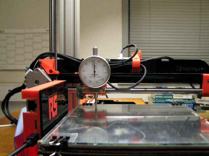
The best way I have found to set the bed and Z axis height up is to try to manually adjust the position of the bed to get an equal dimension at all four corners of the bed. To measure the gap I have used the shank of a 10mm drill bit between the bed and the nozzle and adjusted the Z axis lead screw by hand. Once I have the four corners as equal as possible you can then move the x and y axis to the centre of the bed and set the Z height using the drill bit. Once there is slight contact between the nozzle and drill bit set G92 Z10.
Dave M
This is how I do it, the visual way, do not know what this measure thingie is called in english, a measure watch?? - nah, me don't think so (see pics) - and yes, before you ask - I do of cause compensate for the weight diffenrence (52gram) with a helium ballon :-)
Erik
|
Re: The bed should never have been created with MDF January 01, 2014 04:15PM |
Registered: 10 years ago Posts: 256 |
For stiffness and lightness foam sandwich as used in F1 cars and ocean racing yachts cant be beat. For the skins carbon triaxial fabric, for the filling either nomex or divinycell as thick as possible
Stick it all together then put in a vacuum bag on 12 mm glass plate and leave to cure
regards
Andy
Ormerod #318
www.zoomworks.org - Free and Open Source Stuff
Stick it all together then put in a vacuum bag on 12 mm glass plate and leave to cure
regards
Andy
Ormerod #318
www.zoomworks.org - Free and Open Source Stuff
|
Re: The bed should never have been created with MDF January 01, 2014 04:46PM |
Registered: 10 years ago Posts: 135 |
Erik
Just since you asked in England we call the measure watch a "Dial Test Indicator" DTI for short. What the yanks call it is anyones guess. By coincidence I fetched one from my workshop only today thinking I'm going to need that.
Andy
I cant wait for your Carbon fiber Nomex foam sanwich heatbed support design to appear. Come on now you started so you need to finish!
Dieter
The support structure is indeed plywood with the bed itself MDF.
DC42
I agree with your thoughts. Here is my take. Reinforce the back of the bed with thin 20mm alu angle from B&Q there is just room I think. Get anew heat spreader made with two cutouts instead of one. leaving the hole over the pcb hole for a third mounting. Reinforce the central rib with aluminium continued out to the mounting hole. Fix and adjust the bed at three points.
Rory
Edited 4 time(s). Last edit at 01/01/2014 05:38PM by Rory166.
|
Re: The bed should never have been created with MDF January 01, 2014 07:55PM |
Registered: 10 years ago Posts: 256 |
Quote
Rory166
Andy
I cant wait for your Carbon fiber Nomex foam sanwich heatbed support design to appear. Come on now you started so you need to finish!
It would be a cool mod to go with the carbon x-axis parts also on the wish list!
regards
Andy
Ormerod #318
www.zoomworks.org - Free and Open Source Stuff
|
Re: The bed should never have been created with MDF January 01, 2014 08:56PM |
Registered: 10 years ago Posts: 176 |
Hi,
I still waiting for my Ormerod to arrive , and I don't know the the bed material is MDF. I don't like MDF too, I'm in Asia country with hot and humid weather. condense humidity will soften MDF a little, and while operating, the thin MDF board heat up a little and might warp. I have several prototype using MDF with bad luck.
I still waiting for my Ormerod to arrive , and I don't know the the bed material is MDF. I don't like MDF too, I'm in Asia country with hot and humid weather. condense humidity will soften MDF a little, and while operating, the thin MDF board heat up a little and might warp. I have several prototype using MDF with bad luck.
|
Re: The bed should never have been created with MDF January 02, 2014 02:40AM |
Registered: 10 years ago Posts: 66 |
Rory166
Thanks, noticed that now, should be ok once you stiffen it up.
True168
Put some wood sealer or varnish on it if moisture will be a problem. Sealing it should work.
I think the idea behind using ply and mdf is to keep it as light as possible for high speed movement.
Dieter
Ormerod 257
Thanks, noticed that now, should be ok once you stiffen it up.
True168
Put some wood sealer or varnish on it if moisture will be a problem. Sealing it should work.
I think the idea behind using ply and mdf is to keep it as light as possible for high speed movement.
Dieter
Ormerod 257
|
Re: The bed should never have been created with MDF January 02, 2014 10:14AM |
Registered: 12 years ago Posts: 116 |
Quote
dc42
Surely the bed is essentially supported at 3 points, with the two outer corners not really providing support? I'm tempted to remove those 2 screws completely. With the printing plate made of rigid glass, and the heater PCB being rigid too, I don't think it makes much sense to support it at more than 3 points. It is theMDFplywood ribs that keep the 3 support points stable relative to the bearings - and I think they do that quite well.
dc42's response is right - the MDF is heavily constrained by the plywood parts under it, and the outer two corners really don't do much. The PCB/aluminium/glass sandwich should easily overcome the movement of the MDF, and keep the bed flat. Remove the two corner screws. The bed compensation should take care of the rest.
It is possible that the PCB, as it heats up, moves the bed. In this case, do the bed compensation when the bed is at working temperature.
Initially, we had an MDF bed that was more of a triangle - most reprap beds are supported (and adjusted) using a three-point method. We then made the MDF square to support the cardboard insulator and add a bit more insulation, but then it kind of just floated around, so we decided to add the corner screws.
Ian
RepRapPro tech support
|
Re: The bed should never have been created with MDF January 02, 2014 11:55AM |
Registered: 10 years ago Posts: 14,672 |
Thinking further about it, I'll replace the 2 outside front screws by short ones, that clamp the aluminium and bed heater together but do not penetrate the MDF.
Large delta printer [miscsolutions.wordpress.com], E3D tool changer, Robotdigg SCARA printer, Crane Quad and Ormerod
Disclosure: I design Duet electronics and work on RepRapFirmware, [duet3d.com].
Large delta printer [miscsolutions.wordpress.com], E3D tool changer, Robotdigg SCARA printer, Crane Quad and Ormerod
Disclosure: I design Duet electronics and work on RepRapFirmware, [duet3d.com].
|
Re: The bed should never have been created with MDF January 02, 2014 03:46PM |
Registered: 10 years ago Posts: 4 |
Hi All,
I have replaced the entire MDF bed and ply pieces with (customised) laser cut 5mm Plexiglas / Acrylic parts and removed redundant cut-outs (only left a small square cut-out for the temperature sensor plug) and it is vastly improved and the cardboard appears to provide sufficient heat insulation as my new bed is barely warm. I would strongly like to suggest this as an improvement to future versions.
I also replaced the stock piece of float glass with a slightly thicker piece (4mm) as the supplied one did not seem flat enough. As mentioned else where by dc42 White PVC insulation tape works much better than the aluminium foil on the corners of the glass.
Regards,
Kevin
Ormerod 245 (in South Africa)
|
Re: The bed should never have been created with MDF January 02, 2014 04:31PM |
Registered: 10 years ago Posts: 1,230 |
Quote
dc42
Thinking further about it, I'll replace the 2 outside front screws by short ones, that clamp the aluminium and bed heater together but do not penetrate the MDF.
That's what I did...and placed strong springs between the alu/bed heater and bed on 2 of the 3 remaining adjusting screws, no more fiddeling with nut, now I can keep an eye on the Dial Test Indicator (thanks Rory for naming the beast) while adjusting
Erik
|
Re: The bed should never have been created with MDF January 02, 2014 04:33PM |
Registered: 10 years ago Posts: 14,672 |
Thanks KK, I was already wondering whether 4mm float glass would be better. It wouldn't work with the bed clips from The Range 59p photo frame because they are barely able to handle the 3mm glass + alu + bed heater + mdf tabs, but I've ordered these clips which should handle the extra 1mm easily.
Large delta printer [miscsolutions.wordpress.com], E3D tool changer, Robotdigg SCARA printer, Crane Quad and Ormerod
Disclosure: I design Duet electronics and work on RepRapFirmware, [duet3d.com].
Large delta printer [miscsolutions.wordpress.com], E3D tool changer, Robotdigg SCARA printer, Crane Quad and Ormerod
Disclosure: I design Duet electronics and work on RepRapFirmware, [duet3d.com].
|
Re: The bed should never have been created with MDF January 02, 2014 04:41PM |
Registered: 10 years ago Posts: 135 |
Looking at the build instructions I cannot see any mention of the fifth mounting screw. I seems a shame that the aluminium heat spreader does not cover the 5th hole in the pcb to allow the adjustment of both together. Once that is in place the two outer screw will be irrelevant as the MDF has negligible stiffness at that point.
Rory
DC
Nice tip abot the 10mm clips. I am concerned about the lack of stiffness of the MDF bed and have started making a T shaped frame out of 3mm aluminium sheet. At present there is a 40mm flange all along the rear bearing mounting plane and near the central spine but off set slightly to allow the mounting hole. I will have to cut back the flange beyond the edge of the linear bearings but I want to keep some depth of flange for stiffness sake. I may well fit the bed a little higher which will loose a few mm of build height but I think worth it in terms of the stiffness of the bed mounting. At the moment the structure feels very stiff and light. when it is compete and all holes drilled I must weigh it and compare with the original. I have bent the aluminium to form the flanges and tied the flanges together by bolting on angle pieces from offcuts. A Welded structure would be better but not within my current repertoire.
Rory
Edited 1 time(s). Last edit at 01/02/2014 05:54PM by Rory166.
Rory
DC
Nice tip abot the 10mm clips. I am concerned about the lack of stiffness of the MDF bed and have started making a T shaped frame out of 3mm aluminium sheet. At present there is a 40mm flange all along the rear bearing mounting plane and near the central spine but off set slightly to allow the mounting hole. I will have to cut back the flange beyond the edge of the linear bearings but I want to keep some depth of flange for stiffness sake. I may well fit the bed a little higher which will loose a few mm of build height but I think worth it in terms of the stiffness of the bed mounting. At the moment the structure feels very stiff and light. when it is compete and all holes drilled I must weigh it and compare with the original. I have bent the aluminium to form the flanges and tied the flanges together by bolting on angle pieces from offcuts. A Welded structure would be better but not within my current repertoire.
Rory
Edited 1 time(s). Last edit at 01/02/2014 05:54PM by Rory166.
|
Re: The bed should never have been created with MDF January 02, 2014 04:46PM |
Registered: 10 years ago Posts: 1,230 |
Quote
KK
...As mentioned else where by dc42 White PVC insulation tape works much better than the aluminium foil on the corners of the glass...
Kevin
Ormerod 245 (in South Africa)
alu is a good reflecting material, but almost imposible to mount without crinkles and if thats the case flat white paint is better
Erik
|
Re: The bed should never have been created with MDF January 02, 2014 04:53PM |
Registered: 12 years ago Posts: 1,611 |
|
Re: The bed should never have been created with MDF January 02, 2014 04:53PM |
Registered: 10 years ago Posts: 1,230 |
Quote
Rory166
Looking at the build instructions I cannot see any mention of the fifth mounting screw...
Rory
Only in Bed Plane Compensation, The old-fashioned way; by hand!
[www.reprappro.com]
Erik
|
Re: The bed should never have been created with MDF January 02, 2014 05:06PM |
Registered: 12 years ago Posts: 1,611 |
KK - Can you post some pictures of your Plexiglass bed, and perhaps post your files? Our Mendel kit uses 4mm glass, but it will be heavier and take a bit longer to warm up. We haven't noticed the glass being out of level, and the bed compensation should mitigate it, if it is.
Rory - Heated bed assembly, second step here: [www.reprappro.com]
"Assemble the heated bed as shown, using the five cap head screws to fix the Aluminium heat spreader plate to the heatbed PCB. The fifth central screw between the heated bed connectors is not shown in these pictures. Use two M3 nuts on each screw. This gives enough spacing for the cardboard insulator to fit beneath this assembly when it is fitted to the Y axis of the machine."
Ian
RepRapPro tech support
|
Re: The bed should never have been created with MDF January 03, 2014 02:28AM |
Registered: 10 years ago Posts: 4 |
Hi Ian
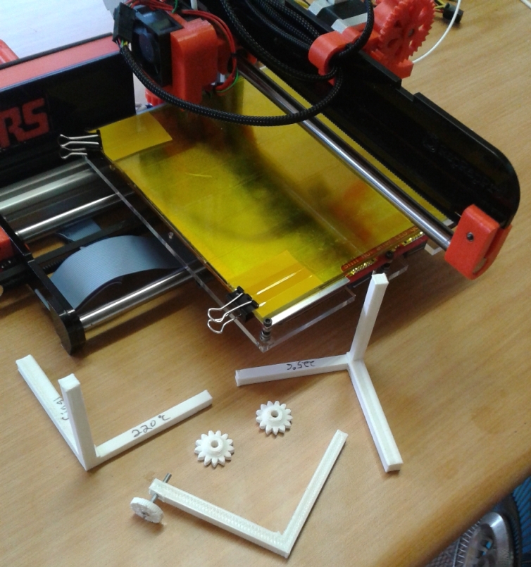
Here are some pictures of my Plexiglas bed with 4mm float glass and longer (20mm) bolts for the old fashion & manual bed compensation (which works very well together).
In addition to removing the large cut outs in the standard bed I also added some more "meat" arround the mounting holds for the bolts as the original bolt holes were very close to the edges.
I have attached my files in dxf and cdr format if others want to cut their own parts. (You may notice that I also added a hole in the cross rib right under the bed which I was going to stick a rod of carbon fibre through for even more strength but this was not neccessary in the end as it was rigid enough).
In addition to the added rigidity I think using Plexiglas over MDF & Ply also improves the look and feel of the overall machine.
Lastly I also had the issue of a gap existing between the bearing supporting the hot end and the x-axis rib, so I stuck a 1.5mm thick brass strip on the side of the x-axis rib to take up the gap which works well.
Regards,
Kevin
Edited 2 time(s). Last edit at 01/03/2014 02:35AM by KK.
Ormerod 245 (in South Africa)
Here are some pictures of my Plexiglas bed with 4mm float glass and longer (20mm) bolts for the old fashion & manual bed compensation (which works very well together).
In addition to removing the large cut outs in the standard bed I also added some more "meat" arround the mounting holds for the bolts as the original bolt holes were very close to the edges.


I have attached my files in dxf and cdr format if others want to cut their own parts. (You may notice that I also added a hole in the cross rib right under the bed which I was going to stick a rod of carbon fibre through for even more strength but this was not neccessary in the end as it was rigid enough).
In addition to the added rigidity I think using Plexiglas over MDF & Ply also improves the look and feel of the overall machine.
Lastly I also had the issue of a gap existing between the bearing supporting the hot end and the x-axis rib, so I stuck a 1.5mm thick brass strip on the side of the x-axis rib to take up the gap which works well.

Regards,
Kevin
Edited 2 time(s). Last edit at 01/03/2014 02:35AM by KK.
Ormerod 245 (in South Africa)
Attachments:
open | download - 20140103_084841_side_sm.jpg (422.2 KB)
open | download - My-bed.dxf (77.7 KB)
open | download - My-cross-rib.dxf (80.4 KB)
open | download - My-rib.cdr (14.7 KB)
open | download - My-rib.dxf (80.8 KB)
open | download - My-bed.cdr (14.5 KB)
open | download - My-cross-rib.cdr (15.7 KB)
|
Re: The bed should never have been created with MDF January 03, 2014 04:48AM |
Registered: 10 years ago Posts: 1,230 |
|
Re: The bed should never have been created with MDF January 03, 2014 04:51AM |
Registered: 10 years ago Posts: 191 |
Hi Kevin,
Awesome! Thanks for sharing.
What is the thickness of the plexiglas you are using and what type?
Markus
XBee & electronics blog: [lookmanowire.blogspot.com]
Awesome! Thanks for sharing.
What is the thickness of the plexiglas you are using and what type?
Markus
XBee & electronics blog: [lookmanowire.blogspot.com]
|
Re: The bed should never have been created with MDF January 03, 2014 06:22AM |
Registered: 10 years ago Posts: 1,230 |
Quote
markbee
What is the thickness of the plexiglas you are using and what type?
Markus
"I have replaced the entire MDF bed and ply pieces with (customised) laser cut 5mm Plexiglas / Acrylic parts..."
[forums.reprap.org]

Sorry, only registered users may post in this forum.