The Progression of Kit278
Posted by victors
|
The Progression of Kit278 January 03, 2014 07:46AM |
Registered: 10 years ago Posts: 62 |
Hi guys
I received my kit 278 around 2 weeks ago. Much excitement which turned into great disappointment over the next 5 days. And just as I started getting the first part printed I ended in hospital with a nasty kidney stone (as painful as advertised!) and lost nearly 2 weeks. But I am OK again... thus back to my machine. I am an electronic engineer and I have my own 50m² man-cave with a machine shop next door. So this should have been simple. But is was not. I had many of the same problems many of the others complain(ed) about. So far I agree with a few that this product was not well thought through at all. The price I ended up paying was equivalent to what my sister in-law takes home, per month, as an HR manager. I know it was much cheaper than other Reprap models but what made it attractive was the wonderful ad I received from RS. BTW, I am based near Johannesburg, South Africa. Some of you might feel it is a mainstream country (seeing that the world hailed that $%^ ex-president bomb planting terrorist as a god and hero last month) but it is out of the way and difficult to get one-off units. So RS's offer was really a breath of fresh air. The ad mentioned that it came in kit form and could be assembled in 2 hours. I ordered within 48 hours from that ad. Now, if you can lie about that then the rest is also suspect. Some of my problems (which many might have):
1) Y axis. Really flimsy. The plywood kept popping off the single slider bearing. It needs to be fastened somehow. PLAN: Cable tie it or something. It just cannot work like this.
2) The Y belt keeps on popping out. You need at least 2 people to get it in, one for holding tension and the other to manipulate the belt an push it into place. When I saw this I immediately thought back to my old balsa wood model aeroplane days. PLAN: It needs a tensioner or something. There is way too much play in the belt.
3) The entire IR sensor thing is a pain. Every time the X,Y or Z misses the mark I basically need to pull the plug. Luckily these are only 0.5NM motors else I reckon serious damage could be done when it tries to push an axis past the limit. PLAN: Install micro switches on both sides of the X axis as well as one for the Z axis. The Z axis is particularly irritating when it misses the mark and just keeps on dropping (and never getting there). Trying to stop the motors from Pronterface does not work either.
4) The bed. I can see what the designers tried to do but obviously it was not that successful. If I calibrate Z on the one corner then it is seriously out in the middle. The 4-corner compensation does not make sense as well ( I do understand the math very well). If the bed is non-flat, springy then I understand that the plane can be compensated for BUT this requires a repeatable Z axis. At the moment I do not have a problem with the Z axis keeping in that it must only lift the head up and not run up and down. The gear system as well as the V groove thread has huge backlash. I don't see the weight of the X axis taking up the slack. PLAN: Get the bed mechanically as flat as possible. The idea is that the Z axis must only be lifted for each layer (never to go down unless calibrating or starting again).
5) Bed & heat & power supply: I don't know if some of you got ABS to work? I eventually got the printer to print a mangled version of the turning knob in PLA. But I decided to buy some more filament for the holidays and the importer only had ABS. The extruder seems quite happy for now. It pumps put ABS at 250C with no problems. The problem is the bed is battling to get to over 100C. I believe the PSU cannot handle this requirement. Also keep in mind that the room was at 25C with the door open. This is Africa. We might be running out of Rhinos but we will always have the heat. At this very moment it is 28C (measured with Fluke 62 IR meter). But the problems do not end there. I believe the PSU is dropping out. I run a job from Pronter and then watch the temperatures. Then at some stage I could hear the plastic crackling from the extruder (probably crap hot at that stage). I manually turned the extruder gear to get the burning ABS out. BUT the USB link was dead. Hence no feedback or control. It seems that the extra power requirements causes the PSU to drop out, crash the Duet and then it requires to switch everything off, unplug USB and then re-power. I have not had even the remotest chance to even start testing ABS at all. I manually lowered the head on to the table, with the bed and hotend on max, manually extruded the gear and tried to get anything to stick to the bed. F-all. The bed was not hot enough. PLAN: This thing needs more power! I know PC PSUs are the bomb these days but each unit's trip level differs. I don't really think these PSUs are designed to maintain the current at 12V. So I will need to go buy myself a mother-less proper transformer or something. BTW, we use 220V over here. Maybe yours work better at 110VAC, Suggestion time: Re-layout the heater PCB for 110V and 220V and drive it with a triac and protect with a PTC. The PCB will end up with thinner and longer tracks but you will only switch it for short durations... plus you can probably fry an egg on it (thus more stable temperatures above 100C)
6) X Axis: That laser cut beam is skew! If it only bent in one direction it would be OK-ish but mine seems to be following a sine wave . Twisting in the one direction make the problem go away but then the exhaust section is lower than the nozzle and it actually scrapes the PLA from the bed as it prints. PLAN: That thing must go. Looking at replacing the whole thing with extruded Al or something. Another option is to put another linear slide in. I already got myself some 8mm rods and bearings. That "follower" is following the wrong path.
7) The electronics: I design my own CPU cards. Many of them are FPGA based, are 32 bit, GBytes of RAM and other features and cost wayyyy less than 100 pounds.
a) Your power distribution is a mess. This USB dependency, 5V to 3.3V and related problems just plainly sucks. Do you use the built-in WDT? It seems a crash requires a complete powerdown and unplugging of everything.
b) The board came unprogrammed. There was no life. I eventually re-flashed it to get it going.
c) Incompatible with the SD card. I bought myself a proper SanDisk and that seems to be working now. The socket is also buggered. I will have to break it out to an external SD interface as I don't see that thing lasting a few more insertions.
d) Ethernet interface! Oh boy. Only once did the serial interface show me a HTTP GET request and only once did I get a login screen. And this is your preferred interface?
e) All the cables go in at the bottom and then this lone blue connection goes to the top. Guess how many times mine pulled out. Any chance of routing it to a pin to the bottom?
8) Firmware and operation: OK, Ethernet is so far out for me, so I cannot comment on that. The Pronterface interface is all I currently I can work with. I can not yet tried to print from SD card. Printing over USB sucks! It is like the controller is on steroids. I have modified my Sli3er output to try and go slower but it seems as though the thing is rushing through steps. It does not gradually move between two XY positions. It sprints! Then the extruder also makes this brave attempt to do something. The end result is stringy pieces over longer distances and little blobs over short distances. If I manually control the extruder (from Pronter) and move the XY I can actually create nicer extrusions that via USB printing. PLAN: I can looking at something much simpler. I have a very cheap Silabs Si 8051F345 chip in mind with 32+ I/Os, 32KB of Flash, running at 25MHz (+- 20MIPS). Yes, it is an 8bit micro but it is stable and very cheap. I can get them for around $5. The TI stepper drivers are around $8 from RS and my biggest expense will probably be the PCB. But it is a shame that I have paid so much for a system that has so many problems out of the box. I recently did a project for Bombardier where I used this exact microcontroller and added a port for a ConnectOne module. Can use either WIFI or Ethernet, runs off simple AT commands and costs $35 per unit.
Some thoughts:
1) If you guys charged 20% more I still would have bought it via RS (and I believe others would also) IF this would improve the build quality. Unfortunately you now have 500 units out there and probably more on order and only a handful of people who actually got to print anything.
2) Selling via RS solved your distribution problems but you are going to get creamed when e.g. 20%+ of the customers start returning these things. RepRapPro's name will suffer and RS might just start recovering costs from you. So I don't know how bad it is yet. Maybe it is just me and 3 other guys having problems.
3) I will still try and solve the problems on my side. The thing might not look the same in the end but just maybe I can (a) get it going or (b) reuse the parts.
I am actually busy with 3x other CNC machines. The one (that might interest people on this forum) is a machine that can expose PCBs directly from Gerber files. Thus, in a short while, I might be able to supply one-offs of normal single or double sided PCBs. Why do such a thing? Because I can make 3mil track and gaps ;-) It basically does what you would do with a v-groove router, just much neater. These other CNC machines was the actually the main reason for buying the Ormerod (working nearly off the shelf) to make parts for the other machines.
Until later guys.
|
Re: The Progression of Kit278 January 03, 2014 08:28AM |
Registered: 10 years ago Posts: 176 |
Hi Victors,
I'm from Asia country , ordered Ormerod 15th from RS but been messed up and re-order twice and still waiting for Ormerod to arrive. ( RS said estimate will be end of this month )
While waiting, I'm looking at this forums and feels that its a little "dangerous " to gamble with this machine. I spend nearly 2 months of my salary on this machine, I'm an electronic technician for the past 20 years, and built my own several CNC too.
I don't know if my machine will run nicely when I received from RS, seems a lot of problem , especially using ATX power supply for industrial machine seems a big NO NO to me. 12V rail from ATX power design are not design for near full load operation for long time. Most of 12V output from ATX power actually not feedback into optocoupler for regulation, it only rely on 5 V output which connected to optocoupler to be able to regulate the voltage. Thats means the 12V will not very stable output, although it can supply high current.
I'm thinking of building Prusa I3 instead.
Thank you.
Regards,
Ew
|
Re: The Progression of Kit278 January 03, 2014 08:45AM |
Registered: 10 years ago Posts: 14,672 |
Hi victors, thanks for sharing your experience. I too had a number of difficulties getting #072 to work, but it's working quite well now. Some comments:
- Y axis plywood popping off the single bearing: I've not had this problem, but another user has reported the same thing on this forum.
- Y- belt: I find it easy enough to tension and fit by myself. I don't have anything wedging it in the slot, and the only time it has popped out is when the Y motor tried to run beyond the physical end of the travel, due to a firmware bug that is now fixed. Maybe the tolerance on the laser cutting isn't tight enough and the slot is too wide in some kits.
- Z axis backlash and bed-levelling: the only time I have seen much backlash was when I had a worn z-gear, which I have subsequently replaced. I agree that it is better to get the bed level so that compensation is not needed. The glass should be flat enough, however if your X-axis plate is wavy then the Z-height will vary along the X-travel.
- X axis: the x-rib and x-plate I received originally needed filing in order to fit them together without bending. I expect RRP will send you new ones if you ask.
- The IR sensor is working well for me, but only after I changed the values of the 2 resistors on the sensor board as I detailed in another thread, and replaced the 50W halogen ceiling light directly above the Ormerod by an LED one. Without those component changes, it is very sensitive to sunlight and strong incandescent light. I have designed a further modification to use modulated IR light so as to further reduce the sensitivity to ambient light, however I believe RRP are looking to do something similar, so I have this on hold for now.
- Like you, I had to buy a different SD card. The latest firmware has an extra startup delay, so I might be able to use the original one now.
- I haven't tried printing ABS yet. I may try heating the bed to 100C today. I like your idea of using mains power and a triac for the bed heater, although I can see that this would not be a good idea in a kit for which many of the customers would not be safe wiring mains electricity. Also, I'm not sure how to provide mains power to the moving bed safely, in particular how to eliminate the possibility of the wires fracturing, or touching the bed and melting.
I suspect that it would be difficult to make a PCB bed heater whose resistance is high enough and uniform enough to run on mains power. An alternative solution could be a thicker aluminium plate, with several power resistors on the underside, attached via countersunk screws sunk into the top. Maybe increase the glass thickness to 4mm to better spread the heat in the area over the tops of the screws.
With mains power to the bed heater, it might be possible to power the rest from a 19V laptop supply, which would be smaller and neater than the ATX power supply.
- Yes, the blue IR sensor lead pulls off the pin easily. Suggestion: solder a longer wire to that lead and terminate it in e.g. an 8-way IDC connector, if you can find one that doesn't have wide edges. Just using a longer wire might help a lot.
- I agree, the power distribution on the board is not good. See the thread on stability of the 3.3V supply for a discussion of some of the issues, and some mods that some of us have done to the board.
- And I agree that the firmware needs a huge amount of improvement, in particular to make the Ethernet interface more reliable and more functional.
Large delta printer [miscsolutions.wordpress.com], E3D tool changer, Robotdigg SCARA printer, Crane Quad and Ormerod
Disclosure: I design Duet electronics and work on RepRapFirmware, [duet3d.com].
|
Re: The Progression of Kit278 January 03, 2014 08:47AM |
Registered: 10 years ago Posts: 66 |
Hi Victors
I got my no 257 from RS South Africa and based in Cape Town, yes it was expensive and is buggy. I have had quite a few issues with mine, one the belt not staying in place and so on. Mine is missing the hot end but this is being resolved by Ian but otherwise all works ok and smooth after a lot of fiddling (a lot!). I think the bed heater story and power supply is an issue but I will see when I get to printing.
I don't think it is a bad machine but rushed to market and yes I think RS may drop this as fast as a hot potato! We will see with time. In the mean time it is what it is and one of the least expensive 3D printers out there. So I will work with it and do what needs to be done to get it stable and working properly.
One thing is for sure, I don't think this kit is ready for public consumption and if you buy one (hopefully the green ones will have a lot sorted) expect to struggle and fiddle a lot, mine took just over 10 hours build time up to electronics testing.
If I had read all this on the forums as of today, I have would not have purchased one... yet. I am sure a lot of issues will be solved in the next few weeks.
Dieter
|
Re: The Progression of Kit278 January 03, 2014 08:59AM |
Registered: 10 years ago Posts: 14,672 |
Hi tru168,
The 12V rail on the Alpine PSU supplied to me is rated at 32A, so I think it should be OK running at 16A, which I believe is about what the Ormerod takes with everything running. But I take your point about the 12V supply not being independently regulated from the 5V supply in low-cost ATX PSUs. I'm wondering whether to get a 12V 20A psu such as this one. Or maybe this 15V PSU if it turns out that 12V is insufficient to raise the bed temperature to 100C for ABS printing.
Large delta printer [miscsolutions.wordpress.com], E3D tool changer, Robotdigg SCARA printer, Crane Quad and Ormerod
Disclosure: I design Duet electronics and work on RepRapFirmware, [duet3d.com].
|
Re: The Progression of Kit278 January 03, 2014 09:33AM |
Registered: 10 years ago Posts: 176 |
Hi DC42,
I repair bunch of industrial power supply everyday. The one that you show is industrial power supply, its not expensive at all. If I'm using Ormerod, I will use one like this., which is far reliable than ATX . By following this forum, I can see the hot end plus heated bed consumption around 16A, and 4 stepper motor will draw nearly 1A each , especially when we print a circle. I will suggest at least 12V 25A switching power unit. I guess 15 V might stressed others parts as well, Its a bad news for me that the bed can't reach 100c for ABS,( I need most of my industrial parts printed in ABS material.)
Anyway, really hope Reprap Pro can solve all problems in very short time. ( and yes , I can see Reprap Pro really work hard on it )
Regards,
EW
|
Re: The Progression of Kit278 January 03, 2014 09:46AM |
Registered: 10 years ago Posts: 14,672 |
Hi tru168,
The Duet board is supposed to be good for up to 35V input, so 15V would hardly be stressing it. The stepper drivers are constant current chopper type ones. So the only component that might get overstressed @ 15V is the extruder heater, and a series resistor of about 0.68 ohms would take care of that.
Large delta printer [miscsolutions.wordpress.com], E3D tool changer, Robotdigg SCARA printer, Crane Quad and Ormerod
Disclosure: I design Duet electronics and work on RepRapFirmware, [duet3d.com].
|
Re: The Progression of Kit278 January 03, 2014 10:03AM |
Registered: 10 years ago Posts: 176 |
Hi Dc42,
Thanks for the info about the Duet board ratings. seems ok to use 15V, and don't forget the 12V fan, although 3 V higher than its ratings , some small brushless fan can't really take any voltage higher than its rating. I don't know what fan Ormerod used, but thats a small problem if you want to operate it at 15 V , either drop its voltage a little or just use other type of fan which can take 15v . should be ok I think.
Ew
|
Re: The Progression of Kit278 January 03, 2014 10:11AM |
Registered: 10 years ago Posts: 14,672 |
Good point, I forgot about the fan!
[EDIT: 3 or 4 x 1N4001 diodes in series with the fan should drop the excess 3V.]
Edited 1 time(s). Last edit at 01/03/2014 10:57AM by dc42.
Large delta printer [miscsolutions.wordpress.com], E3D tool changer, Robotdigg SCARA printer, Crane Quad and Ormerod
Disclosure: I design Duet electronics and work on RepRapFirmware, [duet3d.com].
|
Re: The Progression of Kit278 January 03, 2014 11:55AM |
Registered: 10 years ago Posts: 14,672 |
I've just done some tests on bed temperature. First, I measured the 12V supply with bed heater on but extruder heater off:
At terminals on ATX power board: 11.44V
At terminals on Duet board:11.38V
Across bed heater pads on Duet board: 11.33V
At bed heater: 11.05V
I then raised the bed temperature to 65C as I normally do, then on to 100C. It only took a few more minutes. I then set it to 120C, which took a while longer, but it is there now. The bed heater LED is on nearly all the time, so this is about the limit. Ambient temperature is 20C with no draughts.
If I buy one of those industrial PSUs that really does provide 12V rather than 11.44V, and feed it straight into the Duet board using thick wires, then I should have at least 5% extra voltage and 10% extra heating power, which should be more than enough. So I won't be using a 15V supply.
I always heat up the bed before running setbed.g, then start the print. So I don't have the extruder heater running for a long time without extruding.
Large delta printer [miscsolutions.wordpress.com], E3D tool changer, Robotdigg SCARA printer, Crane Quad and Ormerod
Disclosure: I design Duet electronics and work on RepRapFirmware, [duet3d.com].
|
Re: The Progression of Kit278 January 03, 2014 12:18PM |
Registered: 12 years ago Posts: 116 |
We supply a 12V 20A power supply with our Mendel kits, very similar to the ones dc42 linked. One of Adrian's Ormerods has one of these PSUs, and he hasn't had any trouble with it dropping out. It's possible they are better regulated, with better capacitors, as they expect to have a variable load. However, they are a bit of a pain to wire up (see [www.reprappro.com] ), which is why we switched to ATX.
Also, you can turn up the voltage on them a bit. For ABS bed temperatures, it's handy to run the PSU at about 13V. See: [www.reprappro.com]
Ian
RepRapPro tech support
Also, you can turn up the voltage on them a bit. For ABS bed temperatures, it's handy to run the PSU at about 13V. See: [www.reprappro.com]
Ian
RepRapPro tech support
|
Re: The Progression of Kit278 January 03, 2014 12:42PM |
Registered: 10 years ago Posts: 14,672 |
Thanks Ian, I've just ordered the 25A version (it was only £1 more than the 20A one) - and I can see from the photo that there is indeed a preset to adjust the output voltage.
Large delta printer [miscsolutions.wordpress.com], E3D tool changer, Robotdigg SCARA printer, Crane Quad and Ormerod
Disclosure: I design Duet electronics and work on RepRapFirmware, [duet3d.com].
Large delta printer [miscsolutions.wordpress.com], E3D tool changer, Robotdigg SCARA printer, Crane Quad and Ormerod
Disclosure: I design Duet electronics and work on RepRapFirmware, [duet3d.com].
|
Re: The Progression of Kit278 January 08, 2014 09:25AM |
Registered: 10 years ago Posts: 62 |
Hi guys
I got myself a monster lab PSU (car battery emulator). Regulated 13.8V at 30A (32A surge). Transformer based, huge filter caps. The thing is physically bigger than the printer itself ;-) About $250USD.
So it (1) will not drop out to +-11V, (2) the noise is a lot less than switchmode and (3) the extra 1.8V (over and above the drop to +-11V) should help heat up the bed a lot better. A quick calculation shows an increase from the 16A (assumed) to 18.4A. That would result in 62W more power for the extruder heater and bed.
If this works then you guys can start looking at battery chargers. Over here in South Africa I have seen a few high current car battery chargers that are designed for a fairly constant output. And some of the Chinese versions were quite cheap.
I will add resistance to the extruder heater circuit. I don't think the 1.8V (12 + 1.8) will harm the heater too much. As soon as the temperature hits the mark it should switch off. But the control loop might cause it now to overshoot. I have nice fat 15A diodes in stock with Vf of around 0.5V. Maybe 3 of them in series should do the trick to get nearer to 12V.
For the fan I will add a LM317 regulator (minimum 2.5V drop = 11.3V max) or just do the same diode trick. The risk, however, is that at the initial startup the effective voltage might still be 13.8V until some current flows. This might kill the fan's electronics. Still need to check overshoot of the PSU. So a regulator might still be the best option (safest for now). I will check and report back.
For the belt problem on the Y axis I will implement the cable tie trick. Should hold it.
My X axis is still not straight. I got myself some 8mm rod and bearings. I would like to get rid of that "runner bearing" and properly get it to run on 2x rods. When you look down the length of the laser cut piece it looks like it is wobbling on the middle of the part. I don't think it is due to the part maybe warping during laser cutting but rather the weight on this beam. It is actually bending and the bearing is following this contour. Another option is to add an angle Al extrusion to the plastic and then let the bearing run on the metal instead. But for that I would need that runner bearing to be extended 2 to 3 mm further, which requires a new printed part. For that it would be nice to be able to actually print something so I can make the parts ;-( So I reckon a few iterations and I will be there.
I am going to add micro switches on the X and Z. I will parallel them with the IR circuit. This should take away that annoying run-away and rattling motors when it misses the table/homing position.
So far I have had absolutely no luck getting any sign of life from the Ethernet again. Pronterface/USB still creates movement similar to Parkinsons. When running the circle.g code it tries to get to the vertices as fast as it can. If I don't think it is the USB comms, rather some delay (or lack of delay) in the controller. If I manually fiddle with the gcode and give a long distance between 2 points it looks like it is trying to run it at maximum speed. I will check to see if there is a new firmware version available and then flash that. If that does not work I am going to rip the whole controller out and replace it with my own. I have already written a Gcode parser and there is still a lot of remaining work, but I cannot continue rebooting, reinserting SD cards and battling with Ethernet. I want to print not debug. Of all the "sucky" things on this printer the controller sucks the most. Maybe I should just get involved with the Duet's code and try and rewrite that.
|
Re: The Progression of Kit278 January 08, 2014 09:58AM |
Registered: 12 years ago Posts: 116 |
Hi victors
Copy your gcode to the SD card and run it from there, not from Pronterface. It will improve your printing no end. The serial communication is not fast enough, so it's stopping and waiting for the next command after each move. It is something we plan on improving, and offering more options to get gcode onto the SD card, but we're busy fixing other things at the moment.
Regarding your ethernet - do you get the green light coming on when you plug in an ethernet cable, that is plugged into your router? If you do, that's usually a start. After that, though there is a possibility of a poorly soldered board causing problems, poor supply of 5V power, and dodgy SD cards, it's down to getting the network settings correct. I haven't had a board that I haven't been able to connect to, though I appreciate I get to work in a 'test' environment.
Your other mods sound interesting!
Ian
RepRapPro
|
Re: The Progression of Kit278 January 08, 2014 10:11AM |
Registered: 10 years ago Posts: 62 |
Ian
OK, will do the SD card thing.
Ethernet: The green light comes on. I have swapped the SD card for a SanDisk one and it seems to work much better. I have tried to use 192.168.1.14 and 192.168.0.14 (my normal range is 192.168.0.x) (and others). Only once, while monitoring serial comms, I saw an HTTP Get command on the serial link and then the login page appeared on my browser (Chrome). I will start checking for solder connection problems. Will also check any comms with Ethereal. Thinking about it the comms did happen when fiddling with the cable.
I need to get this thing started. I have 3 rolls of ABS itching to be printed into something plus my wife is going to kill me if this machine is going to just stand idle (she does the business's books ;-)
|
Re: The Progression of Kit278 January 08, 2014 10:30AM |
Registered: 10 years ago Posts: 14,672 |
Are you able to ping the Duet from the computer reliably?
BTW although I got Ethernet working reliably, I've reverted to Pronterface/USB now. The Ethernet interface is currently less functional than Pronterface. In particular, there is no facility to print or copy files over Ethernet (so you still have print from SD), and there is no way to read the G31 data over Ethernet, so I can't do Z-probe calibration (which I need to re-do frequently because of varying amounts of head sag).
Edited 1 time(s). Last edit at 01/08/2014 10:35AM by dc42.
Large delta printer [miscsolutions.wordpress.com], E3D tool changer, Robotdigg SCARA printer, Crane Quad and Ormerod
Disclosure: I design Duet electronics and work on RepRapFirmware, [duet3d.com].
|
Re: The Progression of Kit278 January 08, 2014 11:24AM |
Registered: 10 years ago Posts: 62 |
DC
No ping. Currently it is dead. But the green light comes on so I agree it might be some lose connection somewhere. I will check it out under the microscope later tonight.
The other problem I have is that the SD socket is busy packing up. I have only removed and inserted an SD about 3 times and the last time I had to pull it out with a pair of pliers. So I reckon that avenue will soon be buggered as well. Did I mention before that I don't particularly like this controller ? ;-(
This is why I think I need to design my own controller and get away from all this sadness.
|
Re: The Progression of Kit278 January 08, 2014 11:44AM |
Registered: 10 years ago Posts: 119 |
Quote
victors
DC
No ping. Currently it is dead. But the green light comes on so I agree it might be some lose connection somewhere. I will check it out under the microscope later tonight.
The other problem I have is that the SD socket is busy packing up. I have only removed and inserted an SD about 3 times and the last time I had to pull it out with a pair of pliers. So I reckon that avenue will soon be buggered as well. Did I mention before that I don't particularly like this controller ? ;-(
This is why I think I need to design my own controller and get away from all this sadness.
I had the same issue with my SD card and socket where it was very hard to extract the SD card from the printer, this was however due to the case, I just took a look to see where it was catching and then took it apart and filed the hole a tad bit where it was catching and its now very easy to remove, granted I still have to use something to push the SD card first for the socket to spring it out but at least I can grip it with my fingers.
I know this may be silly me saying this, but you are aware that the SD card socket has a push release on it?
I am not a fan of Atmel devices, but that's down to not really needing to use them, I have always used PIC Devices for all my designs, everyone has their own favourites and mine is that, but saying that I do rather like this chip, granted it was a pain a took a lot of work to get the development side set up, but once set up the IDE is rather nice.
I may in the future try and have a go at making a controller using a PIC32 for a laugh to see if would work or not, could be fun.
Paul
RS Ormerod No 436
|
Re: The Progression of Kit278 January 09, 2014 04:47AM |
Registered: 10 years ago Posts: 62 |
Paul
I did not have the time I wanted to "play" with the machine but I did check out the SD socket this morning. You are correct, there is quite of bit of roughness on the enclosure. Scraped some off. Then I started taking it in and out several times. Seems to be working better. There might be something in there.
Yes, I know it is a Push-Push type. I use the GSM SIM version a lot. For a stationary system like this I would rather use a full sized SD card and friction fit. Infact I might just put one externally on a breakout. Both my laptops have full size SDcard readers and I will get a multi-reader for my big PC as well. This beats fiddling with a screwdriver and tweezor to get it in and out as well as inserting it in the USB or full SD adapter.
I hate PICs ;-) One of my friends (who studied with me) works at Microchip. A while back we had a chuckle about how bad the PIC architecture is, especially for larger projects. I use PICs very selectively. They do have their place but when it comes to structured C/C++ projects there is no comparison between a PIC and e.g. an ARM processor. Atmel, in general, is a fairly good manufacturer. Until quite recently I used a lot of their 8051 products. It seems their RISC products are more popular that the older generation micros, like the 8051. I have had the opportunity to do many projects on PICs and then re-do them on e.g. 8051. No matter what Microchip claims their final executable code ends up a lot bigger than other CPUs (sometimes 4 to 1 ratios). The PIC instruction sets have features that allow you to write extremely small and efficient sections of code, but as soon as you try to do C stuff it fall apart (frame pointers, memory access, local variables, recursive functions etc...). At the moment I am a great fan of the 8 bit 8051 compatible chips from SiLabs. On average they run 12 time faster per same clock and some of them clock up to 100MHz. Silabs also makes from generic micros to very specialised versions (e.g. Si1000 RF, F350 24 bit ADC). I also work a lot with different types of ARM processors. This seems to be the way to go. Even Intel makes ARM processors now. I have a little 32bit NXP LPC ARM-based CPU board that runs 40MHz on very little power. This concept works because ARM only keeps to the IP design and lets the silicon guys do their thing. But on Altera FPGAs I use NIOS2 a lot (softcore CPU). Friggen awesome. Not that fast but you can design just about anything else on the same chip. I recently bought a few MicroSemi SmartFusion2 kits. The ones I bought has a 50 000 logic element FPGA, 160MHz ARM CPU, 2x DDR controllers, Ethernet, CAN and lots, lots more. And all the dev tools are free. These chips are still $160 but the smaller ones are much, much cheaper. But for me to "remake" the Duet I will stick to a simple F345 (Silabs) running at 25MHz. Lots of I/O, very easy to program and extremely error/fault resistant. I use these on high speed trains with shaky power supplies and they have been going strong for 18 months now.
I hate IDEs. Just about everything I have to do now involves IDEs like Eclipse. I still like command line compilers. When I get to a site I just want to copy the compiler to a PC and type "cc -o program.exe program.c" and get the program executable seconds later. But if this means that I need the IDE to get my version of the Duet working then maybe I should just go for it.
I still need to check out the solder joints on my Duet board. I don't think any chip is damaged (tried to operate within ESD guidelines). So I believe the Ethernet problem might be a loose connection and I think the firmware needs some serious attention.
|
Re: The Progression of Kit278 January 09, 2014 05:30AM |
Registered: 10 years ago Posts: 66 |
Done with PICs, I will use TI MSP chips any day before PIC16 or the likes for small things. My latest love affair has been the STM32's ARM Cortex M3 and so cheap to get various setups via ebay.
When my machine works properly, I am thinking of building another 3D printer, own design or some variation of many existing ones and then I will throw a STM32 at it. At least I should be able to print the parts on the Ormerod for a better new machine design. A nice long term project once my ormerod works properly!
To change the ormerod is just to much effort or make a new board to replace the duet is just not worth it. That time will be better spent on building something new from scratch. The lessons learnt from the ormerod design are expensive (I CONSIDER IT SCHOOL FEES) and the mistakes made with the design but despite the frustration it has been "educational"!
Dieter
Ormerod #257
|
Re: The Progression of Kit278 January 09, 2014 05:34AM |
Registered: 10 years ago Posts: 119 |
Hello victors
Yeah, when I had to file the hole out for the DC power cables I decided on cleaning up the other holes, this was where I noticed that the SD card socket was push loaded so I filed out that slot until it went is and out with ease.
Granted I still have to use something to push in to insert and to pop out the sd card but I can now gript the SD card with my finger and thumb.
I may have to do the same for the USB hole due to the new cable that I brought that was longer than the once supplied doesn't fit in the current hole, so I will do that when I get my replacement duet board.
Yeah, a few of my friends also hate the PIC and love the Atmel chips and just refuse to use the PIC for anything, see I will use the Atmel for a project if it works out cheaper and better else I will use a PIC, I have been lucky so far and have only needed to use PIC's.
TBH I don't think PIC's are that bad, saying that there is room for improvement like the compiling of the C code, granted the optimization helps and does reduce the code a lot, I did a long time ago use to code in assembly on the PIC which resulted in very small code, but due to the introduction of their C compiler I got lazy and now use that and have forgotten a lot of the assembly coding.
One thing that I do really hate about Microchips Libraries is half of it just doesn't work, way too many bugs in there, however using the datasheets its easy to resolve the issues in the libraries, grated a load of time is wasted doing this but pah.
I did at one time use the old 8051, 8080, 8086 and the good old trusty Z80 devices, now that's going back many years the other devices and brads I haven't heard of so I cannot comment on those.
Yeah, I think an IDE should make things better and easier to do stuff, sadly some times its a pain to get up and running, I use to work that way where we compiled code into objects and then link them all into an executable or required binary.
Getting Eclipse up and running was a pain at first but after reading another post pointed to by dc I did finally get the firmware all compiling fine.
Well I had a few issues with my board listed below:
1: USB ground side pins which are to hold the socket to the PCB had no solder on it, pin 1 and 2 of the USB socket looked like it had a solder bridge on it, so I had to clean that up and also solder the USB socket to the board.
2: Had a pin on the Ethernet socket that had no solder on it al all, only notice that when I was locating a short to ground issue that my board has on pin AD7 on the Sam device, so I fixed that missing solder.
3: Had the issue that loads of people have been having where the 4 screw holes on the board are too small and needed to be drilled a little bit larger, it states that on the instructions, so I was aware of it.
Yeah I need to buy another wrist strap, somebody thought it would be funny pinching my blue one and replacing it with a bright pink one
Apart from that its not been that bad.
Paul
RS Ormerod No 436
Quote
victors
Paul
I did not have the time I wanted to "play" with the machine but I did check out the SD socket this morning. You are correct, there is quite of bit of roughness on the enclosure. Scraped some off. Then I started taking it in and out several times. Seems to be working better. There might be something in there.
Yes, I know it is a Push-Push type. I use the GSM SIM version a lot. For a stationary system like this I would rather use a full sized SD card and friction fit. Infact I might just put one externally on a breakout. Both my laptops have full size SDcard readers and I will get a multi-reader for my big PC as well. This beats fiddling with a screwdriver and tweezor to get it in and out as well as inserting it in the USB or full SD adapter.
Yeah, when I had to file the hole out for the DC power cables I decided on cleaning up the other holes, this was where I noticed that the SD card socket was push loaded so I filed out that slot until it went is and out with ease.
Granted I still have to use something to push in to insert and to pop out the sd card but I can now gript the SD card with my finger and thumb.
I may have to do the same for the USB hole due to the new cable that I brought that was longer than the once supplied doesn't fit in the current hole, so I will do that when I get my replacement duet board.
Quote
victors
I hate PICs ;-) One of my friends (who studied with me) works at Microchip. A while back we had a chuckle about how bad the PIC architecture is, especially for larger projects. I use PICs very selectively. They do have their place but when it comes to structured C/C++ projects there is no comparison between a PIC and e.g. an ARM processor. Atmel, in general, is a fairly good manufacturer. Until quite recently I used a lot of their 8051 products. It seems their RISC products are more popular that the older generation micros, like the 8051. I have had the opportunity to do many projects on PICs and then re-do them on e.g. 8051. No matter what Microchip claims their final executable code ends up a lot bigger than other CPUs (sometimes 4 to 1 ratios). The PIC instruction sets have features that allow you to write extremely small and efficient sections of code, but as soon as you try to do C stuff it fall apart (frame pointers, memory access, local variables, recursive functions etc...). At the moment I am a great fan of the 8 bit 8051 compatible chips from SiLabs. On average they run 12 time faster per same clock and some of them clock up to 100MHz. Silabs also makes from generic micros to very specialised versions (e.g. Si1000 RF, F350 24 bit ADC). I also work a lot with different types of ARM processors. This seems to be the way to go. Even Intel makes ARM processors now. I have a little 32bit NXP LPC ARM-based CPU board that runs 40MHz on very little power. This concept works because ARM only keeps to the IP design and lets the silicon guys do their thing. But on Altera FPGAs I use NIOS2 a lot (softcore CPU). Friggen awesome. Not that fast but you can design just about anything else on the same chip. I recently bought a few MicroSemi SmartFusion2 kits. The ones I bought has a 50 000 logic element FPGA, 160MHz ARM CPU, 2x DDR controllers, Ethernet, CAN and lots, lots more. And all the dev tools are free. These chips are still $160 but the smaller ones are much, much cheaper. But for me to "remake" the Duet I will stick to a simple F345 (Silabs) running at 25MHz. Lots of I/O, very easy to program and extremely error/fault resistant. I use these on high speed trains with shaky power supplies and they have been going strong for 18 months now.
Yeah, a few of my friends also hate the PIC and love the Atmel chips and just refuse to use the PIC for anything, see I will use the Atmel for a project if it works out cheaper and better else I will use a PIC, I have been lucky so far and have only needed to use PIC's.
TBH I don't think PIC's are that bad, saying that there is room for improvement like the compiling of the C code, granted the optimization helps and does reduce the code a lot, I did a long time ago use to code in assembly on the PIC which resulted in very small code, but due to the introduction of their C compiler I got lazy and now use that and have forgotten a lot of the assembly coding.
One thing that I do really hate about Microchips Libraries is half of it just doesn't work, way too many bugs in there, however using the datasheets its easy to resolve the issues in the libraries, grated a load of time is wasted doing this but pah.
I did at one time use the old 8051, 8080, 8086 and the good old trusty Z80 devices, now that's going back many years
the other devices and brads I haven't heard of so I cannot comment on those.Quote
victors
I hate IDEs. Just about everything I have to do now involves IDEs like Eclipse. I still like command line compilers. When I get to a site I just want to copy the compiler to a PC and type "cc -o program.exe program.c" and get the program executable seconds later. But if this means that I need the IDE to get my version of the Duet working then maybe I should just go for it.
Yeah, I think an IDE should make things better and easier to do stuff, sadly some times its a pain to get up and running, I use to work that way where we compiled code into objects and then link them all into an executable or required binary.
Getting Eclipse up and running was a pain at first but after reading another post pointed to by dc I did finally get the firmware all compiling fine.
Quote
victors
I still need to check out the solder joints on my Duet board. I don't think any chip is damaged (tried to operate within ESD guidelines). So I believe the Ethernet problem might be a loose connection and I think the firmware needs some serious attention.
Well I had a few issues with my board listed below:
1: USB ground side pins which are to hold the socket to the PCB had no solder on it, pin 1 and 2 of the USB socket looked like it had a solder bridge on it, so I had to clean that up and also solder the USB socket to the board.
2: Had a pin on the Ethernet socket that had no solder on it al all, only notice that when I was locating a short to ground issue that my board has on pin AD7 on the Sam device, so I fixed that missing solder.
3: Had the issue that loads of people have been having where the 4 screw holes on the board are too small and needed to be drilled a little bit larger, it states that on the instructions, so I was aware of it.
Yeah I need to buy another wrist strap, somebody thought it would be funny pinching my blue one and replacing it with a bright pink one
Apart from that its not been that bad.
Paul
RS Ormerod No 436
|
Re: The Progression of Kit278 January 10, 2014 04:11AM |
Registered: 10 years ago Posts: 62 |
Got printer to print PLA. Much happiness!
My one problem was that the IR sensor and the plastic part closest to the bed scraped the plastic off as it was printing. Not good. I could also not get my nozzle down low enough. So I filed it off. See IRmod.jpg.
After it cleared, bed at 65C and nozzle at 205C, I printed the snowman. See snow1.jpg and 2.
Next I tried the coat hanger. The backwash messed it up. The print lifted up and the printer tried to print over this. I had to manually lift the Z axis a bit for it for correct. Also, around 00h05 my one friend sent me a Whatsapp message. The cellphone was about 1 meter away. I picked it up and replied. As soon as I hit send the controller crashed! Keep in mind that this is still with the original power supply. But I will try and emulate this again. Maybe bigger caps, thicker wire and the new PSU (with RF choke inline)?
So the backwash botthered me and I decided to print Andy's (??) part. I held a piece of paper under the fan and it immediately seemed to work. DF_inside.jpg and DF_outside.jpg shows the part.
For the weekend I am going to (1) try and straighten the Perspex beam with an Al extrusion, (2) hook up the more powerful PSU to test out ABS, (3) get the bed more level and (4) see if there are any broken connections around the Ethernet section. Y belt is still not stiff enough. But for now I am printing PLA ;-) ABS capability would be nice seeing that I have 3Kg of filament on the shelf.
|
Re: The Progression of Kit278 January 10, 2014 04:58AM |
Registered: 10 years ago Posts: 66 |
Victors, just glue the one side down of the belt with some super glue where it starts against the vertical piece of wood before the belt exits to the stepper side as the wood locking first part in my opinion is a total failure. Then you can pull it very tight. It should cross lock nice and tight belt on belt. Test it by doing a manual slide by hand a few times with stepper wires unplugged. The plastic side where the return bearing sits was also grabbing the belt and some filing was needed there.
When I built it, I tested all moving parts by hand. A few slides up and down and the belt came off the bed. So did this fix then already among a whole lot of other tweaks. Rock solid since then. No slop or play. I made sure everything ran very smooth yet tight enough before even connecting electronics, one of the reasons I seem to have less mechanical problems than others I think
Dieter
Ormerod #257
|
Re: The Progression of Kit278 January 10, 2014 05:13AM |
Registered: 10 years ago Posts: 176 |
Hi Victors,
From infos from Ormerod users in this forum, the duet board seems to be very sensitive to interference / noise. I don't know how the board's ground plane design ( because 1 month passed and still waiting for my Ormerod to arrive.) if you have some ferrite rings , try to put it on power wires , heated bed wires etc to filter out RF noises from entering to the board.
If you have oscilloscope , you can measure power -ve point to the board -ve point, or any ground point from one corner of the Duet board to another ground point at another corner of duet board. If you can see a lot of noise on scope ( although ground point to ground point are 0 ohm measured by DC , but not for AC or RF if ground plane not design correctly on PC thats means bad ground plane design on PCB caused ground loop to induce noise which can interrupt micro controller easily.
As a ham operator for years, and also vacuum tube amplifier enthausieast , I learnt a lot of knowledge about ground plane layout from building HF transmitters / vacuum tube amplifier .
I will measure the board's noise and find out a solution when I receive mine.
Ew
Edited 1 time(s). Last edit at 01/10/2014 09:45AM by tru168.
From infos from Ormerod users in this forum, the duet board seems to be very sensitive to interference / noise. I don't know how the board's ground plane design ( because 1 month passed and still waiting for my Ormerod to arrive.) if you have some ferrite rings , try to put it on power wires , heated bed wires etc to filter out RF noises from entering to the board.
If you have oscilloscope , you can measure power -ve point to the board -ve point, or any ground point from one corner of the Duet board to another ground point at another corner of duet board. If you can see a lot of noise on scope ( although ground point to ground point are 0 ohm measured by DC , but not for AC or RF if ground plane not design correctly on PC
thats means bad ground plane design on PCB caused ground loop to induce noise which can interrupt micro controller easily.As a ham operator for years, and also vacuum tube amplifier enthausieast , I learnt a lot of knowledge about ground plane layout from building HF transmitters / vacuum tube amplifier .
I will measure the board's noise and find out a solution when I receive mine.
Ew
Edited 1 time(s). Last edit at 01/10/2014 09:45AM by tru168.
|
Re: The Progression of Kit278 January 10, 2014 05:33AM |
Registered: 10 years ago Posts: 62 |
Ew
Yes, I have all that stuff and more. It really didn't bother me till last night (when I started printing for the first time ;-) I just got a PCB back that needs to be assembled. 8 layers, all signals sandwitched between GND planes, friggen expensive onboard PSU chips plus it goes into metal enclosure. I am in the line of business where none of the electronics can ever be allowed to crash. So things like these annoy me ;-(
When I get a chance I will start to isolate which cables are the most likely to pick up EMI. I was sitting around 30cm away when I sent the Whatsapp message (Samsung S3). That was enough to crash it.
Printing from SD does not help either. Even if the WDT gets implemented the controller would still lose its current position.
|
Re: The Progression of Kit278 January 10, 2014 05:59AM |
Registered: 10 years ago Posts: 176 |
Victors,
30cm away from your Samsung S3 and still pickup EMI ?..... :-(
Yes, you are right, I agree that none of PCB designed for production can ever be allowed to crash. Duet board seems still new, and i believe more stable version will be release real soon ( its open source after all , and gathering all infos from users very fast) Since you have good experience designing PCBs , should be easy for you to test it, ( or maybe the board pickup EMI from PSU line as you suspected ) please let us know your findings , so that we can come out with a solution.
Ew
|
Re: The Progression of Kit278 January 10, 2014 05:59AM |
Registered: 10 years ago Posts: 66 |
Ew, Lol, rf stuff at 2.4ghz board design has crazy ground and lead length requirements. Played around with it in the past, everything acts like a small pf capacitor! Duet board should never crash as a result of a cell packet data spewing over everything. Sounds like bad board design, have not looked at my duet board in detail but there should be a good ground plane under it with through holes and lots of decoupling caps all around.
Victors,
If it crashed, X2 most likely got killed with interference, just looking at a photo of the board online here at work. Can't see the bottom but I notice a distinct lack of ground plane around the ARM chip and X2. At least it appears so from the photo and almost no through holes around the ARM to a bottom ground plane. Looks like a simple two layer board. Might need to fit a metal stand off shield around the arm chip in that case that covers X2 too? Seen this done before on boards.
Dieter
Ormerod #257
|
Re: The Progression of Kit278 January 10, 2014 07:12AM |
Registered: 10 years ago Posts: 119 |
Hello dieterzar
There is a huge ground plane around the SAM device, take a look at layer 2 (sorry for low res image)
That blue area around the SAM (ARM) device is connected to GND/0V
Paul
RS Ormerod No 436
Quote
dieterzar
If it crashed, X2 most likely got killed with interference, just looking at a photo of the board online here at work. Can't see the bottom but I notice a distinct lack of ground plane around the ARM chip and X2. At least it appears so from the photo and almost no through holes around the ARM to a bottom ground plane. Looks like a simple two layer board. Might need to fit a metal stand off shield around the arm chip in that case that covers X2 too? Seen this done before on boards.
Dieter
Ormerod #257
There is a huge ground plane around the SAM device, take a look at layer 2 (sorry for low res image)

That blue area around the SAM (ARM) device is connected to GND/0V
Paul
RS Ormerod No 436
|
Re: The Progression of Kit278 January 10, 2014 07:40AM |
Registered: 10 years ago Posts: 66 |
Ah, thanks, difficult to see it on the photo of the board I have, strange how they only covered part of the board but looks on the topside the lm1117 is covered?
That leaves one stupid but important question, how well earthed is the GND line? It should be earthed via the PSU pcb but you never know with chinese made psu. Somtimes they don't do it via pcb in the PSU but in the PC it gets earthed via GND and the fact that the psu casing is attached to the pc casing and other components also attached to the casing creating a common earth and GND.
The reason I ask, we use 3 pin plugs in SA BUT that doesn't stop you from using the 2 pin power cable supplied with a plastic adapter.... means no proper earthing and proper chance of stray RF to work it's magic. I didn't use any of the supplied power cables but a pc cable with an SA power plug on it with an earth wire.
Other than that I think everyone would or should experience the same issues as Victors when it comes to cell phone near the board without a doubt.
Dieter
Ormerod #257
|
Re: The Progression of Kit278 January 10, 2014 07:42AM |
Registered: 10 years ago Posts: 191 |
Hi,
more about printing hangs/ (cpu) freeze in this thread:
Printing hangs/ freezes
Markus
XBee & electronics blog: [lookmanowire.blogspot.com]
more about printing hangs/ (cpu) freeze in this thread:
Printing hangs/ freezes
Markus
XBee & electronics blog: [lookmanowire.blogspot.com]

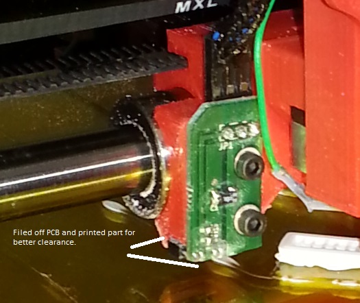
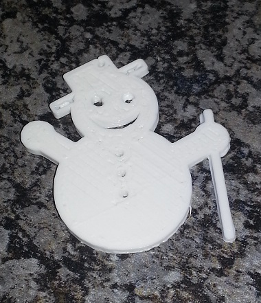
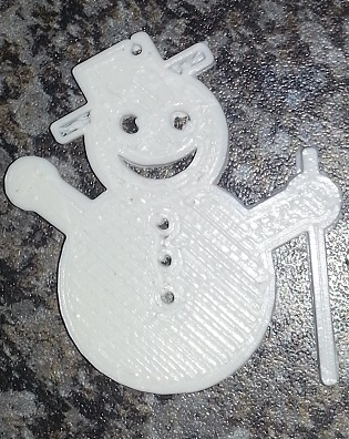
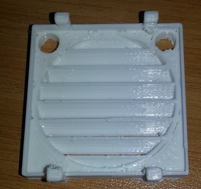
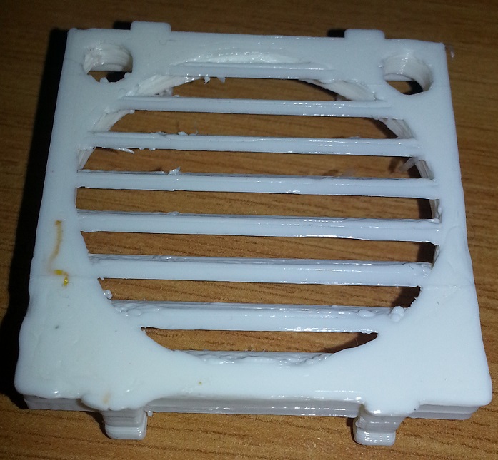
Sorry, only registered users may post in this forum.