The Progression of Kit278
Posted by victors
|
Re: The Progression of Kit278 January 14, 2014 05:22PM |
Registered: 10 years ago Posts: 578 |
A graphics card that needs 500W would cost a hell of a lot more than this kit does (including the PSU) - I think that RRP have made a reasonable compromise in buying a pre-certified low cost PSU (Victors at one time proposed using mains switched direct for the bed - that wouldn't have sold many kits in europe), I don't know what mark-ups get used in your industry, but for the low volume RRP are selling I doubt if the $150 price tag would be passed on directly to the customer, and the cost of th ekit would have hiked a LOT.
I'm surprised though, that they went for a single PSU that provides three rails (and then choose the unregulated rail to power the machine on all of its rails while leaving the regulated ones feeding dummy loads). Personally I'd have gone for an unregulated (maybe unrectified) high power 12V for the heating (since the heating effect of the electrical power is regulated, the power itself doesn't need to be, as long as there IS enough power...), and a separate regulated power supply for the duet (a single 12V that had enough power to drive the onboard regulators (and the fan) to provide stable 5 and 3.3V rails, or maybe just a 5V that could be dropped to 3.3 and hook the fan to the unregulated 12V that powers the heaters)
Edited 1 time(s). Last edit at 01/14/2014 05:24PM by rayhicks.
|
Re: The Progression of Kit278 January 15, 2014 03:40AM |
Registered: 10 years ago Posts: 62 |
Ray
My feeling is that the design should make provision for 2x PSU inputs and that the customer must buy his/her own PSUs as a first option when ordering. PC PSUs are as common as grass and I still have 3 lying around (that I have not yet decided to disassemble yet). RRP can save on volumetric shipping by cutting it out from the contents. If the price has to stay the same (plus package volume) then fill it up with spares and other goodies. E.g. I would really like to have another set or 2 of the hot-end (nozzle, heater block etc...). The rest the client can print themselves. Even the stepper motors are easy to obtain. Just a suggestion.
DC : Sagging head
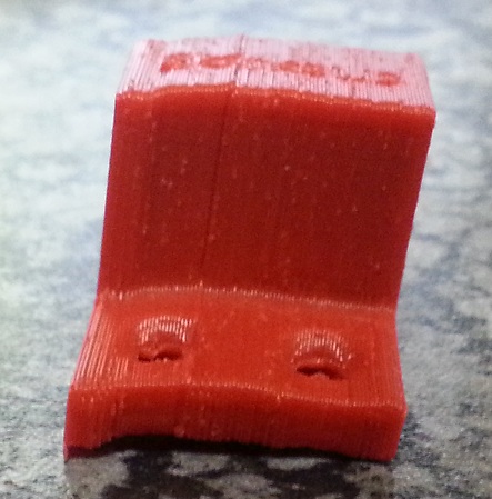
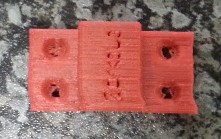
Stayed up until 1am to finish the second head mount. The first one looked better than the earlier printed disasters as I used isolators to remount the screws. But it sagged in the end. I then filed and drilled the first attempted print and installed it. Much better. The 2nd head mount looks perfect, nearly the same look and feel as the original. I reduced infill, so it is heavier but very solid (+- 40 min build). The only problem is that the screw holes, going through to the X carriage, needs to be bigger (6mm as in the original), but I drilled them out. Very little discomfort for such a big gain.
There is much speculation on how to improve this (solid ally, PTFE, ceramic bushes). The main problem seems to be that the heat goes up the screw and has nowhere else to go. My feeling is to give it a proper heatsink. Even this new printer part solution will eventually wear through as the 240C makes its way up and fatigue the plastic. So my idea is to take a piece of angle ally, drill holes to match the head mount and just mount it inbetween the screw heads and printed part. So instead of the heat building up in the screw it now gets distributed in the larger piece of metal heatsink at the top. I don't know if anybody has suggested this but I have the material available and will try this first. Another thing, I will try and check is how much added weight can be added on the X carriage. Maybe a larger block of ally will work better without stressing the X motor too much.
But thanks to the new part I am pack to printing again. I lost an evening but luckily not the head mount ;-)
Thanks guys.
My feeling is that the design should make provision for 2x PSU inputs and that the customer must buy his/her own PSUs as a first option when ordering. PC PSUs are as common as grass and I still have 3 lying around (that I have not yet decided to disassemble yet). RRP can save on volumetric shipping by cutting it out from the contents. If the price has to stay the same (plus package volume) then fill it up with spares and other goodies. E.g. I would really like to have another set or 2 of the hot-end (nozzle, heater block etc...). The rest the client can print themselves. Even the stepper motors are easy to obtain. Just a suggestion.
DC : Sagging head
Stayed up until 1am to finish the second head mount. The first one looked better than the earlier printed disasters as I used isolators to remount the screws. But it sagged in the end. I then filed and drilled the first attempted print and installed it. Much better. The 2nd head mount looks perfect, nearly the same look and feel as the original. I reduced infill, so it is heavier but very solid (+- 40 min build). The only problem is that the screw holes, going through to the X carriage, needs to be bigger (6mm as in the original), but I drilled them out. Very little discomfort for such a big gain.
There is much speculation on how to improve this (solid ally, PTFE, ceramic bushes). The main problem seems to be that the heat goes up the screw and has nowhere else to go. My feeling is to give it a proper heatsink. Even this new printer part solution will eventually wear through as the 240C makes its way up and fatigue the plastic. So my idea is to take a piece of angle ally, drill holes to match the head mount and just mount it inbetween the screw heads and printed part. So instead of the heat building up in the screw it now gets distributed in the larger piece of metal heatsink at the top. I don't know if anybody has suggested this but I have the material available and will try this first. Another thing, I will try and check is how much added weight can be added on the X carriage. Maybe a larger block of ally will work better without stressing the X motor too much.
But thanks to the new part I am pack to printing again. I lost an evening but luckily not the head mount ;-)
Thanks guys.
|
Re: The Progression of Kit278 January 15, 2014 03:57AM |
Registered: 10 years ago Posts: 14,672 |
@victors, there already is a heatsink, and it is the heatsink block that the screws are screwed into. So it's not a case of 240C making its way up the screws, its a case of heat starting at 240C trying to make its way up the nozzle, getting removed to some (hopefully large) extent in the heatsink block, then heat making its way from the heatsink block up the screws. So I think the answer is to improve the cooling of the heatsink so that it remains below the temperature at which ABS softens (and printing the nozzle mount in ABS of course). Two ways to help this are to use good thermal compound when mounting the heatsink, and to use a better fan. The fans shipped with the kit are not ideally suited to applications like this where the back pressure is high. RRP are shipping at least two different types of fan, and one type may work better than the other.
Are you able to measure the temperature of the heatsink block in your setup?
Large delta printer [miscsolutions.wordpress.com], E3D tool changer, Robotdigg SCARA printer, Crane Quad and Ormerod
Disclosure: I design Duet electronics and work on RepRapFirmware, [duet3d.com].
Are you able to measure the temperature of the heatsink block in your setup?
Large delta printer [miscsolutions.wordpress.com], E3D tool changer, Robotdigg SCARA printer, Crane Quad and Ormerod
Disclosure: I design Duet electronics and work on RepRapFirmware, [duet3d.com].
|
Re: The Progression of Kit278 January 15, 2014 05:02AM |
Registered: 10 years ago Posts: 62 |
DC
I can try and measure it with either the IR meter or thermocouple.
What I saw was that the screw heads actually melt into the plastic. With the new design the screw heads have nowhere to go. On the original version it basically slips off the counter sink. I already have plenty of heat sink compound between the block and the heatsink. My fan is running at a dangerously high voltage (still need to put that diod back). So my attempt is going to try and take some heat away from the screw heads.
Solving bad airflow won't be easy now. The only other "easy" way is to increase the thermal mass. The only cheap and obvious place is to use e.g. 40mm x 40mm x 3mm angle ally. Machine a slot in for the Bowden tube, trim the other side and tap and mount on the existing heatsink (I am not at the machine at the moment. Working from mental pictures and the assembly instructions). I can also see a few other options. By increasing the thermal mass and also the exposed area the effect should be more required effort to heat the heatsink and thus better cooling. But the only way to test this is to stick e.g. the themocouple on and try several options. But more mass means more strain on X motor. Somewhere there must be a golden mean.
|
Re: The Progression of Kit278 January 15, 2014 05:35AM |
Registered: 10 years ago Posts: 578 |
Quote
victors
My feeling is that the design should make provision for 2x PSU inputs and that the customer must buy his/her own PSUs as a first option when ordering. PC PSUs are as common as grass and I still have 3 lying around (that I have not yet decided to disassemble yet). RRP can save on volumetric shipping by cutting it out from the contents. If the price has to stay the same (plus package volume) then fill it up with spares and other goodies. E.g. I would really like to have another set or 2 of the hot-end (nozzle, heater block etc...). The rest the client can print themselves. Even the stepper motors are easy to obtain. Just a suggestion.
I agree with all of that (especially the spares part) - they could even include a regulated DC supply (wall wart) for board power, and leave sourcing of an ATX or other " heating" solution to the end user. I'd suggested in another thread (and mentioned earlier in this one) using a 200VA 12V lighting transformer switched by a relay ), and I think I'm going to give this a go soon, probably just for the bed (since it's not pwm driven a relay should cope, though a silicon solution may be a better option), the lighting transformers are very cheap and rated for continuous driving of heating wire in bulb filaments and their inrush current, I'll leave the head running off the ATX initially, but again a relatively cheap DC 50W "desktop" psu could drive this through a mod such as treth has suggested using the external FET output. I'll keep a 12V supply to the board to run the fan, since I don't think the ATX 5V in or the USB 5V have enough margin after their diode voltage drops onto the 5V net to run the 3.3V regulator reliably.
@dc42, I've hooked up a thermocouple into one of the screw holes in the heat sink block and am monitoring ambient temp versus block temperature while printing ABS (reported nozzle temp of 245°C, I'll post the data later when I've got a couple of hours worth. So far the temperature is 19-20°C above ambient and has been from t=10 to t=50.
|
Re: The Progression of Kit278 January 15, 2014 06:01AM |
Registered: 10 years ago Posts: 14,672 |
Quote
rayhicks
I'd suggested in another thread (and mentioned earlier in this one) using a 200VA 12V lighting transformer switched by a relay ), and I think I'm going to give this a go soon, probably just for the bed (since it's not pwm driven a relay should cope, though a silicon solution may be a better option), the lighting transformers are very cheap and rated for continuous driving of heating wire in bulb filaments and their inrush current, I'll leave the head running off the ATX initially, but again a relatively cheap DC 50W "desktop" psu could drive this through a mod such as treth has suggested using the external FET output. I'll keep a 12V supply to the board to run the fan, since I don't think the ATX 5V in or the USB 5V have enough margin after their diode voltage drops onto the 5V net to run the 3.3V regulator reliably.
Isn't it simpler and neater to use a single 12V 25A regulated PSU? Only £21-80 via eBay.
Large delta printer [miscsolutions.wordpress.com], E3D tool changer, Robotdigg SCARA printer, Crane Quad and Ormerod
Disclosure: I design Duet electronics and work on RepRapFirmware, [duet3d.com].
|
Re: The Progression of Kit278 January 15, 2014 07:48AM |
Registered: 10 years ago Posts: 2,472 |
Quote
dc42
@victors, there already is a heatsink, and it is the heatsink block that the screws are screwed into. So it's not a case of 240C making its way up the screws, its a case of heat starting at 240C trying to make its way up the nozzle, getting removed to some (hopefully large) extent in the heatsink block, then heat making its way from the heatsink block up the screws. So I think the answer is to improve the cooling of the heatsink so that it remains below the temperature at which ABS softens (and printing the nozzle mount in ABS of course). Two ways to help this are to use good thermal compound when mounting the heatsink, and to use a better fan. The fans shipped with the kit are not ideally suited to applications like this where the back pressure is high. RRP are shipping at least two different types of fan, and one type may work better than the other.
Are you able to measure the temperature of the heatsink block in your setup?
I am not having any problem with the screws softening the plastic and I can touch the end of the cooling block after the extruder has been at 250 deg for hours without it feeling more than warm, although I did reprint the mount in ABS as a precaution. One problem is that the bolts that clamp the heatsink to the cooling block also hold the fan in place - and the fan is only mounted by its lower two holes. If I tighten these to what I consider a reasonable amount to provide a good clamping pressure between the block and heatsink, it distorts the fan so the blades foul the inside of the fan housing, so I am forced to have a relatively loose clamp between the heatsink and aluminium cooling block. I'll take a look at some different fans to see if I can find one that does not have that issue.
Dave
|
Re: The Progression of Kit278 January 15, 2014 07:58AM |
Registered: 10 years ago Posts: 62 |
DC : PSUs
I think the aim is here to see what will satisfy all current and future users. Ebay is not so good for us South Africans (and probably many other countries as well). But we do have have distributors like Communica and RS. But RS is not good for most because of cost and not every country has a company like www.communica.co.za.
RRP had the right idea to use PC PSUs. I see that now. But I feel the client should buy his own local PSU (certified for that particular country). Also, once you find a local supplier you can buy more/replace when needed. RRP can reduce the package size. In my case the supplied PSU sucks. Even at 27C ambient I battle to get 90C+ on the bed. The voltage drops way below 11V. Some are luckier and 1x PSU is enough. The power board should be designed to take 2x PSU inputs. Maybe just a simpler connector in parallel for just the hot-end, motors and board. But when you need to push the power up you should be able to go and buy an extra one. The PC PSU, at the power needed, is the most generic and easily available type one can use.
My Xytron solution, although friggen awesome, is not cost effective. It costs around $200 to $250 for a new one. And it is huge and its fan makes 10 times more noise.
But it seems in the ATX PSU world they differ a lot. My PC consumes a lot of power. I had an unstable 750W PSU and eventually exchanged it for a 650W ThermalTake. The 650W was more expensive but a lot more stable. So I have learnt not to trust the Wattage as advertized.
|
Re: The Progression of Kit278 January 15, 2014 08:57AM |
Registered: 10 years ago Posts: 66 |
Victors,
I agree with you and was the point I was making in an earlier post about power hungry PC graphics cards. Interestingly PCFormat SA had an issue a few months back on PSU's with some shockers. Some of the more expensive brands really struggled with cooling and voltage stability and ability to handle shock loads. They tested well known brands from $100 - $250 at current ZAR exchange rates.
So the PC PSU is a good idea, I just don't believe current ones supplied are up to the job. Letting the user buy his own is a good idea but I can just imagine the number of people that will buy under rated supplies. So a new breed of problem. I also think a lot of issues I have read about here can be directly attributed to the supply. Ian did ask for suggestions in another post to improve the power distribution section of the design. So suggestions would be welcome I imagine.
Dieter
Ormerod #257
|
Re: The Progression of Kit278 January 15, 2014 09:12AM |
Registered: 10 years ago Posts: 62 |
Dieter
You are right about people buying 'under rated' PSUs. I know some cheap Honko-nese suppliers that will sell you a PC case plus ATX power supply for around $35. So if the client buys something like this he might be thinking that he scored...even buying 2x for a split power system. Then pointing fingers back at RRP for selling a system that crashes every 5 minutes.
So, RRP, suggestion time. If you keep on supplying these power supplies then you will need to load test them at both 110VAC and 220VAC. The problem is that mine only starts giving trouble after some time at high bed/hot-end temperatures. That might end up taking too much time. Maybe just one model up would be better? 650W?
|
Re: The Progression of Kit278 January 15, 2014 10:53AM |
Registered: 10 years ago Posts: 578 |
victors,
most of europe (including the UK), is on 230V@50Hz, just like SA -I'm in the UK and my (Alpine) PSU is fixed voltage (230V) - I wonder if RPP or RS is including the Alps box for export orders in case they land in a 110V region (I notice you've mentioned testing at both voltages a couple of times). Maybe it's just luck of the draw who gets which psu though.
Ray
|
block temperature update January 15, 2014 11:09AM |
Registered: 10 years ago Posts: 578 |
just an update to my note before - it looks like my heatsink block reaches about 20°C above ambient within ten minutes of setting the hotend to 250 (it reported a temp of around 245/246 during the run), then keeps at this level at least for a two hour run:

|
Re: The Progression of Kit278 January 15, 2014 11:23AM |
Registered: 10 years ago Posts: 66 |
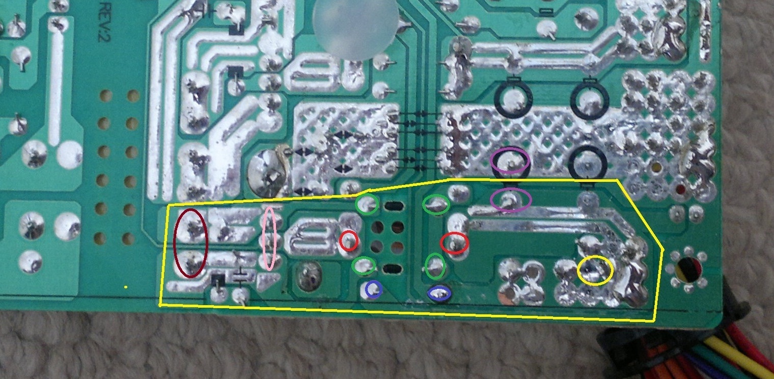
OK, my Alpine just lost it's warranty! lol! Really don't care, opened and had a look at what is going on. 12V out section is a very simple circuit, no feedback and also very little cleaning, no big caps except 1 x 16V 1000uf cap. I have attached a photo of the PSU 12V out section in the yellow block, yellow circle is where 12V wires connect. Purple is the 16V 1000uf cap to ground. Green are 2 x diodes. Blue a resistor and red the heavy gauge choke. Pink looks like back to back diodes for rectification in a transistor package. Brown, is transformer out.
Clearly there is no way from what I can make out that any kind of feed back is taking place off the 12V line. When I have a little more time, I am going to look at the circuit in more detail. What I can say is that there is space on the board for another cap which is left off next to the 16V 1000uf already in there so that will help with load changes.
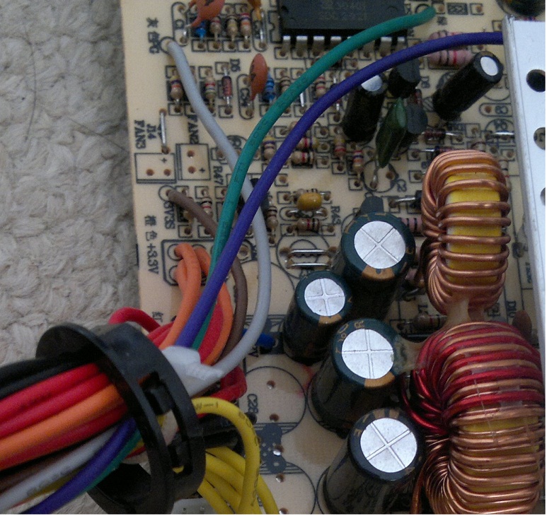
The red wires which are 5V also appear to be a similar setup as 12V at a brief glance. The orange wires out it looks like are the 3v3 lines and there is a lot circuit going on there and the feed back circuit is on that side.
Dieter
Ormerod #257
Clearly there is no way from what I can make out that any kind of feed back is taking place off the 12V line. When I have a little more time, I am going to look at the circuit in more detail. What I can say is that there is space on the board for another cap which is left off next to the 16V 1000uf already in there so that will help with load changes.
The red wires which are 5V also appear to be a similar setup as 12V at a brief glance. The orange wires out it looks like are the 3v3 lines and there is a lot circuit going on there and the feed back circuit is on that side.
Dieter
Ormerod #257
|
Re: The Progression of Kit278 January 15, 2014 11:31AM |
Registered: 10 years ago Posts: 66 |
There is a thin circuit track in the photo that runs back from the back to back diode package passed the transformer but connects to nothing but has a solder pad at the end of it and looks like might have been put there for the possibility of feed back. Hacking the power supply would be easy if I had a circuit diagram to work off.
Dieter
Ormerod #257
Dieter
Ormerod #257
|
Re: The Progression of Kit278 January 15, 2014 11:51AM |
Registered: 10 years ago Posts: 300 |
Quote
dieterzar
Hacking the power supply would be easy if I had a circuit diagram to work off.
Thanks for exposing the insides of your Alpine PSU dietezar. In the topic Can the regulation of the ATX PSU be improved? I was looking for a solution that could be implemented without hacking the PSU. Your findings may help with that.
RS Components Reprap Ormerod No. 481
|
Re: The Progression of Kit278 January 15, 2014 02:19PM |
Registered: 10 years ago Posts: 62 |
Just found a possible ID10t fault. Important. Loosen the vertical screws a little before tightning the fan screws. If you don't then the heatsink does not make good contact with the cooling block. So first make a tight connection between the heatsink and fan and then tighten the head mount screws.
|
Re: The Progression of Kit278 January 15, 2014 04:37PM |
Registered: 10 years ago Posts: 62 |
My temperatures now seem to be OK. Verified it with Fluke 62 IR meter.
X carrier
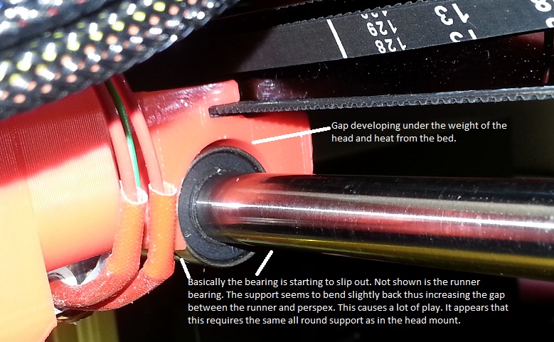
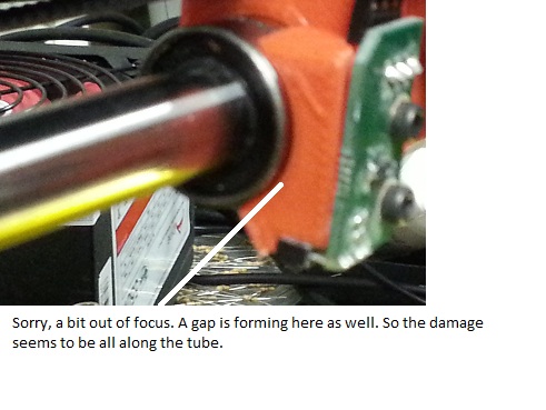
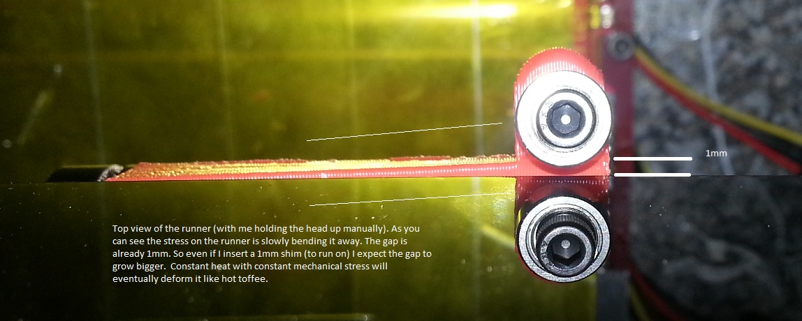
Next rather bad problem. The X carrier (sitting on the bearing) is slowly deforming. Initially it clipped on with difficulty.Now there are gaps and I can slip it on and off with one hand. I just tried to print another simple square rod holder. It is like it is slowly deforming. I realized this when after a few layers the print looked skew.
The bed is at 110C.Ambient is 25C. It seems that the heat radiation and the mechanical pressure is slowly bending the carriage out of shape. The runner bearing is also looking like it is being bent away from the perspex. This results in the entire head sagging. I can lift the head up by 6.5mm. This was quite visible after a few layers that the fan exhaust would knock against the part if it got there (but it just missed it on this design). Because the X carriage is now so loose any movement translates into errors on the printed part.
So the combination of ambient 25C, 110C bed, gravity stress on the open carriage and pressure on the runner bearing is taking it toll. Think about it this way. Take an empty toilet roll, cut a slit in the length, put it over a pipe and apply some torsion on it. It will start to deform. Now add the memory effect of warm plastic getting cold.
So how DaF! am I going to fix this one? ;-(((
It looks like I have to take the whole thing off for now and heat it over a steel pipe with a heatgun and try and bend it in shape (what was that movie: "Bend it Beckham"? Now it will be: "Bend it like Ormerod").
RRP, what type of plastic did you use to print the parts, PLA or ABS? The reason I am asking is that I tried to heat up my ABS part with the heatgun and then tried to manipulate it with my fingers. I could not. I then heated my PLA coat hanger and with very little heat it went all squishy and I could manipulate it (lots of infill). I then took the head mount part (that I reprinted in ABS) and heated it up. It became as squishy as the PLA coat hanger.
Conclusion:
1) The X carriage should be printed in ABS (if not already)
2) Solid, no in fills!
3) No flimsy parts. 3 to 4mm plus all around.
4) Another sister part that clamps from the bottom and completes a solid tube.
At the moment I have serious doubts about this machine, in its current state, to be able to print ABS.
Other ABS operational ideas:
1) Head must be lifter high up before printing job.
2) Gcode must be set to heat the bed up to bonding temperature (110C)
3) When the temperature is reached the print must start and only print a few layers at that higher bed temperature.
4) Then the bed temperature must be dropped to near PLA bed temps (basically before it decides to pop off).
Today ended in a rather disappointment. If anybody has any advice please let me know.
X carrier
Next rather bad problem. The X carrier (sitting on the bearing) is slowly deforming. Initially it clipped on with difficulty.Now there are gaps and I can slip it on and off with one hand. I just tried to print another simple square rod holder. It is like it is slowly deforming. I realized this when after a few layers the print looked skew.
The bed is at 110C.Ambient is 25C. It seems that the heat radiation and the mechanical pressure is slowly bending the carriage out of shape. The runner bearing is also looking like it is being bent away from the perspex. This results in the entire head sagging. I can lift the head up by 6.5mm. This was quite visible after a few layers that the fan exhaust would knock against the part if it got there (but it just missed it on this design). Because the X carriage is now so loose any movement translates into errors on the printed part.
So the combination of ambient 25C, 110C bed, gravity stress on the open carriage and pressure on the runner bearing is taking it toll. Think about it this way. Take an empty toilet roll, cut a slit in the length, put it over a pipe and apply some torsion on it. It will start to deform. Now add the memory effect of warm plastic getting cold.
So how DaF! am I going to fix this one? ;-(((
It looks like I have to take the whole thing off for now and heat it over a steel pipe with a heatgun and try and bend it in shape (what was that movie: "Bend it Beckham"? Now it will be: "Bend it like Ormerod").
RRP, what type of plastic did you use to print the parts, PLA or ABS? The reason I am asking is that I tried to heat up my ABS part with the heatgun and then tried to manipulate it with my fingers. I could not. I then heated my PLA coat hanger and with very little heat it went all squishy and I could manipulate it (lots of infill). I then took the head mount part (that I reprinted in ABS) and heated it up. It became as squishy as the PLA coat hanger.
Conclusion:
1) The X carriage should be printed in ABS (if not already)
2) Solid, no in fills!
3) No flimsy parts. 3 to 4mm plus all around.
4) Another sister part that clamps from the bottom and completes a solid tube.
At the moment I have serious doubts about this machine, in its current state, to be able to print ABS.
Other ABS operational ideas:
1) Head must be lifter high up before printing job.
2) Gcode must be set to heat the bed up to bonding temperature (110C)
3) When the temperature is reached the print must start and only print a few layers at that higher bed temperature.
4) Then the bed temperature must be dropped to near PLA bed temps (basically before it decides to pop off).
Today ended in a rather disappointment. If anybody has any advice please let me know.
|
Re: The Progression of Kit278 January 15, 2014 05:07PM |
Registered: 10 years ago Posts: 578 |
victors,
this must be a combination of your high ambient plus the radiated/convected heat from the bed (not your fault! just probably not something that RRP may not have expected). In my office with ambient 15 (no forced airflow) or 22 with forced airflow, I don't get anything like your damage (I did get some slippage in the x carriage bearing holder, but this was fixed with superglue, and was probably due to mechanical rather than thermal stress).
I think you're hitting the heat deflection temperature of the mounting plastic (which I guess to be PLA rather than ABS) even under low loads - maybe the stresses trapped on freezing are high enough to exert enough pressure to distort the plastic at the temperature it reaches.
if you want some of these parts printed in ABS, pm me your details and I'll run some off for you tomorrow (I'll throw in a delrin heatsink to axis runner too),
Ray
ps if I remember right, slic3r lets you print the first layer at a different temp form the rest as part of its standard configuration dialog, this may be enough, especially since there's a very large thermal inertia in the bed, it would take quite a few layers before it drops (unless it actively waits for that temp to be reached), otherwise, you could manually scroll through the gcodes and add a command to drop the bed temperature at a suitable point and NOT add a "wait for temperature" command.
Edited 2 time(s). Last edit at 01/15/2014 05:13PM by rayhicks.
|
Re: The Progression of Kit278 January 15, 2014 05:13PM |
Registered: 12 years ago Posts: 1,611 |
Quote
victors
RRP, what type of plastic did you use to print the parts, PLA or ABS?
PLA. I thought it was pretty clear that all the printer parts were PLA, but it may be one of those things that we just take for granted. Sitting it over 100C all day IS going to make it go soft. You need to print the x-carriage, and z-axis-runner out of ABS - I will add this to the ABS troubleshooting section I'm writing. We do talk about this sort of problem in the Mendel ABS guide, which I have linked to often: [www.reprappro.com]
The Mendel has a more open x-carriage, and the hot end fan provides more cooling to the surroundings, so the problem doesn't seem as severe with it. The Ormerod controls the air much tighter, so very little washes over the x-carriage, and it's getting hot. Probably the whole x axis linear rod is getting hot, and transmitting through the bearing.
You don't have to print it solid, as it will actually transmit heat quicker through the part solid. We print everything with 30% infill.
Ian
RepRapPro tech support.
|
Re: The Progression of Kit278 January 15, 2014 05:15PM |
Registered: 10 years ago Posts: 62 |
|
Re: The Progression of Kit278 January 15, 2014 05:18PM |
Registered: 10 years ago Posts: 578 |
I'm in the UK, so it may not be the quickest postage but if you find that it sags before you print ABS replacements, let me know.
I guess you know what to print next now though, eh?
I edited my last post to add stuff about dropping the bed temperature by the way, you may not have seen the edit
Cheers
Ray
I guess you know what to print next now though, eh?
I edited my last post to add stuff about dropping the bed temperature by the way, you may not have seen the edit
Cheers
Ray
|
Re: The Progression of Kit278 January 15, 2014 05:23PM |
Registered: 10 years ago Posts: 578 |
|
Re: The Progression of Kit278 January 15, 2014 05:44PM |
Registered: 10 years ago Posts: 62 |
OK, "hand printed" the X carriage, re-tuned the runner and I have a fairly level head again.
Now preheating the bed to 110C while the head is at about 50 to 60mm above the bed.
The print starts at 110C for the 1st layer. Then I drop it to 105C for the 2nd. Then 90C for the rest. The print still sticks.
So far the quality looks quite acceptable. The runner temp is 44C. Cooler block is 46C. X rod and bearing is 50C. The head mount screws are 38C. Ambient is 25C. BTW it is 00h30 in the morning.
At 25% I dropped the bed to 85C. Still sticks. At 30% I took it to 80C. Still sticks. Will leave it there.
Print looks OK. So the effort ws not a complete write-off.
Thanks for all the advice ;-)
I hope my battles and challenges help others as well.
|
Re: The Progression of Kit278 January 15, 2014 07:53PM |
Registered: 10 years ago Posts: 46 |
|
Re: The Progression of Kit278 January 16, 2014 05:05AM |
Registered: 10 years ago Posts: 62 |
SlinBin
Yes, it is usually better to observe the guy going:" One step for man..." before rocketing self into space. Someone needs to melt their printing head first ;-)
And to steal the immortal words of Spider-man's uncle..."With great power comes great responsibility". I was so impressed that my big PSU could drive the whole thing so efficiently that I forgot what the effect was on the rest of the plastic. Well, I assumed this was the norm with 3D printers ... running hot. I have seen people building 3D printer enclosures and one of the reasons was to keep the heat inside. The sad fact is that the PLA does not like it one bit.
I finished my 38 minute print last night (more towards 01h30 in the morning).Still not perfect but well and truly functional. I still need to calibrate/compensate the Z axis. It is slanting away from Y motor. The Ormerod can probably do near perfect prints but I believe I will only get perfection when I complete my own machine (500mm x500mm x 250mm on 16mm rods/pillow cases and 16mm roller bearings, NEMA23 3Nm motors, extremely flat Z and built mostly with mild steel - thus extremely rigid). Some more on/off topic thoughts on this new project. This machine is more for high speed spindle machining (with 25um steps at 1.8deg steps - without any micro stepping), but suffice to say that the high precision parts alone cost way more than the Ormerod. So if I hook an extruder on to it I should be able to print exactly the same way. I had a long think about the bed for this machine. Because the base is standing still ( X and Y moves above) it allows me to use a heavy hot plate element (220V), which I can control via a traic. This means I should be able to get to operating temperature much quicker (also risk of serious overshoot-so it needs better control). And because the bed is stationary I can have built-in fans to cool it down afterwards. In total this is more like a $3000 to $4000 budget project.
OK, how to print ABS, a recap of my expedition yesterday.
1) Starting up: Higher bed temperatures (110C) and weight of head will cause sagging. Start by:
a) Moving Z up high. 10cm?? Ray suggested some shielding material.
b) Preheat the bed to 110C to 115C. 115C makes the ABS stick quicker and I get a very nice finish.
c) Leave the hot-end off or take it to an acceptable temperature (before melting) like 100C. This is to reduce heat build up but quicker ramp up to 240C to 245C. Remember if you don't extrude that the energy in the nozzle needs to go somewhere. But I found leaving it off and ramping up to 245C, when starting the print, does not take that long.
2) You can manually control the bed temperature or do it inside the gcode. Sli3er has a feature to drop the temperatures after a few layers. You can also edit the gcode and add the new target temperatures there. Just search for the Z changes. If you print at .24mm then .48 will be the 3rd layer (??).
If you don't want to edit the code then just do it manually in Pronterface.
a) Print the first layer at 110C to 115C.
b) As soon as it is done drop it to 105C. The bed has a fair amount of thermal inertia. It will take a while.
c) Beyond that you must experiment. I just kept on reducing the temperature by 5C to 10C per layer, BUT my part was small. If the part is larger the amount of time spent per layer can be much longer. So probably good to drop it faster.
d) I ended up at 60C, switching off completely around 90% and the part was stuck like glue when I it was done (no warping). But the bed temperature remained at 57C for quite some time. Thus it can probably be made even lower (sooner). The idea is getting the first layers to stick.
Warping:
I still don't know what will happen with larger parts and if the sudden drop in bed temperture will cause any significant warping of the part.
|
Re: The Progression of Kit278 January 16, 2014 05:33AM |
Registered: 10 years ago Posts: 578 |
looks like a good protocol victors - it's also worth bringing the nozzle temperature down after the print too - I've had the extrusion jam a couple of times when I've spent too long between jobs (slicing, uploading, adjusting axes) with the head at full temperature, then finding it won't extrude since the heat has gone back up the filament swelling/softening it so it can''t push down through the nozzle (it's a well-documented general problem, just I sometimes forget...)
when it has happened, I've retracted a few cm, set the nozzle to 150 or so then extruded back into the (now hardening) plug, I then turn off the heat and let it cool for a few minutes, then ramp up to extrusion temperature, and start extruding slowly while manually assisting the filament (the hobbed bolt strips the filament in the place where it stalled, so the manual assistance is needed to get it moving again) once it's coming out of the nozzle, I stop pushing and extrude a few cm slowly
Ray
|
Re: The Progression of Kit278 January 16, 2014 02:28PM |
Registered: 10 years ago Posts: 62 |
Another night, another print.
I followed some more advice from the forum. Thanks to those geniuses. Will not name names, you know who you are.
BTW, firmware still 57 (I believe there are newer versions??)
1) First I started with my protocol above. This is to insure the ABS bed temperature does not cook the PLA off the X bearing. Start at 110C and now dropped of to 70C during the print.
2) I installed the washing pin spring mod to the Y axis belt. People, this is like V_gra for timing belts. Highly recommended! Enough said.
3) I then re-tensioned the X belt. Cannot really get a spring in there. I got it as tight as possible and then pushed a 0.5mm piece of metal into the X carriage. Nice and tight.
4) Then I increased the Y current to 1000mA. As comparison the X motor is now running at 38.9C and the Y motor at 40.4C, so it is not going up in smoke. BTW, the Z motor is 34C. Rock hard action going on here.
The print is at 25% and so far it looks awesome.
I will post the 3 prints (from horribly bad to friggen awesome) when this one is done.
|
Re: The Progression of Kit278 January 17, 2014 04:51AM |
Registered: 10 years ago Posts: 62 |
The print on Monday went horribly wrong.The head mount sagged and I then had to reprint it in ABS (which was difficult seeing that I could not print ABS correctly in the first place.
The second print was with the new head mount.
The 3rd was with the "fixed" x carriage, after it started to sag, but still lots of play in the belts with the Y motor obviously slipping.
The 4th was an almost perfect print (slightly modified design) with more tension on the X and Y belts and 1000mA on Y motor. Like I said above, the Y motor only increased by 2C to 3C with the extra current.


|
Re: The Progression of Kit278 January 17, 2014 05:54AM |
Registered: 10 years ago Posts: 66 |
Victors,
Thursdays looks really good. All you can do now to improve on that is layer hight which will be a slower print and smaller nozel but that is a really good print I think. Thanks for the info provided on your methods on abs. Looks like the fruits of your labour are paying off.
Dieter
Ormerod #257
Thursdays looks really good. All you can do now to improve on that is layer hight which will be a slower print and smaller nozel but that is a really good print I think. Thanks for the info provided on your methods on abs. Looks like the fruits of your labour are paying off.
Dieter
Ormerod #257
|
Re: The Progression of Kit278 January 17, 2014 06:09AM |
Registered: 10 years ago Posts: 157 |


Sorry, only registered users may post in this forum.