Detailed proposal for IR sensor modulation
Posted by dc42
|
Detailed proposal for IR sensor modulation January 07, 2014 10:24AM |
Registered: 10 years ago Posts: 14,672 |
I attach a fairly detailed proposal for modifying the hardware and firmware to support modulation of the IR sensor. I would appreciate feedback before I implement it, in particular from Ian in case RepRapPro have any similar plans.
Edited 2 time(s). Last edit at 01/07/2014 10:25AM by dc42.
Large delta printer [miscsolutions.wordpress.com], E3D tool changer, Robotdigg SCARA printer, Crane Quad and Ormerod
Disclosure: I design Duet electronics and work on RepRapFirmware, [duet3d.com].
Edited 2 time(s). Last edit at 01/07/2014 10:25AM by dc42.
Large delta printer [miscsolutions.wordpress.com], E3D tool changer, Robotdigg SCARA printer, Crane Quad and Ormerod
Disclosure: I design Duet electronics and work on RepRapFirmware, [duet3d.com].
|
Re: Detailed proposal for IR sensor modulation January 07, 2014 11:31AM |
Registered: 10 years ago Posts: 314 |
Looks very good to me, excited to get such a mod.
Assuming a three way connector shell plus a flying lead at the DUET end and a 4 was connector at the new sensor end, guess it's worth checking that the wrong orientation at the sensor does not cause damage.
Thanks for progressing this.
Ormerod #007 (shaken but not stirred!)
Assuming a three way connector shell plus a flying lead at the DUET end and a 4 was connector at the new sensor end, guess it's worth checking that the wrong orientation at the sensor does not cause damage.
Thanks for progressing this.
Ormerod #007 (shaken but not stirred!)
|
Re: Detailed proposal for IR sensor modulation January 07, 2014 11:38AM |
Registered: 10 years ago Posts: 14,672 |
I'm not planing to design a pcb for this yet, but if/when I do then I agree that either a polarised connector is needed or no damage must be done if it is inverted. I connected my sensor board backwards initially, and whether by luck or good design by RRP, this doesn't cause any damage.
Large delta printer [miscsolutions.wordpress.com], E3D tool changer, Robotdigg SCARA printer, Crane Quad and Ormerod
Disclosure: I design Duet electronics and work on RepRapFirmware, [duet3d.com].
Large delta printer [miscsolutions.wordpress.com], E3D tool changer, Robotdigg SCARA printer, Crane Quad and Ormerod
Disclosure: I design Duet electronics and work on RepRapFirmware, [duet3d.com].
|
Re: Detailed proposal for IR sensor modulation January 08, 2014 02:29PM |
Registered: 12 years ago Posts: 1,611 |
We're having a play around with this ourselves, trying to work out what works and what doesn't. Fortunately we have a small CNC machine that can mill PCBs (just) so we can do rough prototypes ourselves. I'm not exactly sure of the overlap, as I'm not directly involved in the electronics, but I'm sure it would be useful co-development.
Ian
RepRapPro tech support
Ian
RepRapPro tech support
|
Re: Detailed proposal for IR sensor modulation January 08, 2014 02:41PM |
Registered: 10 years ago Posts: 14,672 |
Ian, thanks for that. I was planning to test my ideas by modifying the existing board initially. Do you have any comments on my proposal, in particular the selection of pin number to control the LED, and the changes to the behaviour of the M558 and G32 commands? I don't want to end up with incompatible firmware changes. Alternatively, if you expect to have your solution available very soon, I'll can mine. Send me an email or PM if you prefer to take this offline.
Edited 1 time(s). Last edit at 01/08/2014 02:41PM by dc42.
Large delta printer [miscsolutions.wordpress.com], E3D tool changer, Robotdigg SCARA printer, Crane Quad and Ormerod
Disclosure: I design Duet electronics and work on RepRapFirmware, [duet3d.com].
Edited 1 time(s). Last edit at 01/08/2014 02:41PM by dc42.
Large delta printer [miscsolutions.wordpress.com], E3D tool changer, Robotdigg SCARA printer, Crane Quad and Ormerod
Disclosure: I design Duet electronics and work on RepRapFirmware, [duet3d.com].
|
Re: Detailed proposal for IR sensor modulation January 13, 2014 10:31AM |
Registered: 13 years ago Posts: 119 |
Hello dc42,
Thank you for the great feedback and proposal. I have implemented the changes and milled a prototype PCB. The SMD components have just arrived, so I should be able to test it in the next day or so.
As for your proposed firmware changes, they seem sensible to me. Unless you have the firmware mods done, I'm happy to implement them when I test the hardware.
For your reference, the proximity sensor board is on github here.
|
Re: Detailed proposal for IR sensor modulation January 13, 2014 10:57AM |
Registered: 10 years ago Posts: 14,672 |
Thanks, j-m! btw I found yesterday when the sun was shining that with a 4k3 load resistor, the sensor still saturated with indirect bright sunlight. So I am going to try 3k3 on mine, or back to 2k7 (which I was using originally) if necessary. The idea is to keep the raw reading to not more than 750 with reflected IR + ambient light under all reasonable operating conditions.
EDIT: also I was going to change the firmware to store the last 8 raw readings, so that the current z probe reading can always return an average of the last 4 on and last 4 off readings, which will give more up-to-date readings then the current arrangement.
Edited 1 time(s). Last edit at 01/13/2014 11:01AM by dc42.
Large delta printer [miscsolutions.wordpress.com], E3D tool changer, Robotdigg SCARA printer, Crane Quad and Ormerod
Disclosure: I design Duet electronics and work on RepRapFirmware, [duet3d.com].
|
Re: Detailed proposal for IR sensor modulation January 13, 2014 11:06AM |
Registered: 10 years ago Posts: 191 |
Hi,
do not want to hijack the thread but did you ever think about inductive distance measuring sensors or are they too expensive? They might be less affected by light and are very, very accurate.
Markus
XBee & electronics blog: [lookmanowire.blogspot.com]
do not want to hijack the thread but did you ever think about inductive distance measuring sensors or are they too expensive? They might be less affected by light and are very, very accurate.
Markus
XBee & electronics blog: [lookmanowire.blogspot.com]
|
Re: Detailed proposal for IR sensor modulation January 14, 2014 11:47AM |
Registered: 10 years ago Posts: 14,672 |
After some discussion with RRP, I've implemented this. I used the scheme described in my original document attached to the first post in this thread, with a few modifications:
1. I used 3K3 as the load resistor instead of 4K3 because I found the phototransistor could still saturate when the sun was shining.
2. I changed the firmware to keep track of the last 8 readings and maintain the sums of the last 4 odd and even readings, so that instead of only having a new value every 5 polls, a new value is returned on each poll. Polling currently occurs at intervals of about 6ms. So the old method gave a reading averaged over 30ms which could be up to 30ms out of date, so on average it's the value 30ms ago. The new method gives a reading averaged over 48ms which may be up to 6ms out of date, so on average it's the value 27ms ago and with less jitter.
3. When modulation is being used, the G31 command returns the calculated value and the average high-value. I don't bother reporting the average low-value, it isn't needed and can be calculated from the other two anyway. The high-value is needed to make sure the phototransistor isn't going into saturation. So a response to G31 of "400 (450)" means the calculated average is 400, and the average of the high values only is 450 (therefore the reading when the IR emitter is off averages 50 in this case).
Here is a photo of the modified sensor board. I cut the track leading to the IR emitter, soldered a BC817 above the cut track with the base pin bent upwards, and added a 1K resistor from the base to a header pin epoxied to the top of the board. In fact the header pin needs to point up and right, I had to bend it to clear the z-nut trap.
To test it, I calibrated the z-homing at 1mm nozzle height, giving me a setting of G31 Z1.0 P475. I then did a series of G30 bed probe tests, and determined that the head usually overshoots a little, so that the final G31 reading is about 483. If I then turn on a 60W incandescent lamp about 30 cm from the bed, the peak reading goes up to about 730. The calculated reading also rises, but only to about 500. So the effect of the ambient light on the reading has decreased from about 247 to about 17. It's still a bit sensitive to ambient light, but the sensitivity has been reduced by a factor of 14.5. The practical upshot of this is that when I do a bed probe or z-axis home, the effect of having that light on is make the nozzle just over 0.1mm too high. Without modulation, having the same light on makes the nozzle 2.5mm too high.
I can see that the G31 reading is more variable with the light on than off. I think this is due to 50Hz modulation in the light. If I can find the time, I'll look at running the ADC on a timer interrupt, doing conversions for the z-probe and the thermistors in the background.
Large delta printer [miscsolutions.wordpress.com], E3D tool changer, Robotdigg SCARA printer, Crane Quad and Ormerod
Disclosure: I design Duet electronics and work on RepRapFirmware, [duet3d.com].
1. I used 3K3 as the load resistor instead of 4K3 because I found the phototransistor could still saturate when the sun was shining.
2. I changed the firmware to keep track of the last 8 readings and maintain the sums of the last 4 odd and even readings, so that instead of only having a new value every 5 polls, a new value is returned on each poll. Polling currently occurs at intervals of about 6ms. So the old method gave a reading averaged over 30ms which could be up to 30ms out of date, so on average it's the value 30ms ago. The new method gives a reading averaged over 48ms which may be up to 6ms out of date, so on average it's the value 27ms ago and with less jitter.
3. When modulation is being used, the G31 command returns the calculated value and the average high-value. I don't bother reporting the average low-value, it isn't needed and can be calculated from the other two anyway. The high-value is needed to make sure the phototransistor isn't going into saturation. So a response to G31 of "400 (450)" means the calculated average is 400, and the average of the high values only is 450 (therefore the reading when the IR emitter is off averages 50 in this case).
Here is a photo of the modified sensor board. I cut the track leading to the IR emitter, soldered a BC817 above the cut track with the base pin bent upwards, and added a 1K resistor from the base to a header pin epoxied to the top of the board. In fact the header pin needs to point up and right, I had to bend it to clear the z-nut trap.

To test it, I calibrated the z-homing at 1mm nozzle height, giving me a setting of G31 Z1.0 P475. I then did a series of G30 bed probe tests, and determined that the head usually overshoots a little, so that the final G31 reading is about 483. If I then turn on a 60W incandescent lamp about 30 cm from the bed, the peak reading goes up to about 730. The calculated reading also rises, but only to about 500. So the effect of the ambient light on the reading has decreased from about 247 to about 17. It's still a bit sensitive to ambient light, but the sensitivity has been reduced by a factor of 14.5. The practical upshot of this is that when I do a bed probe or z-axis home, the effect of having that light on is make the nozzle just over 0.1mm too high. Without modulation, having the same light on makes the nozzle 2.5mm too high.
I can see that the G31 reading is more variable with the light on than off. I think this is due to 50Hz modulation in the light. If I can find the time, I'll look at running the ADC on a timer interrupt, doing conversions for the z-probe and the thermistors in the background.
Large delta printer [miscsolutions.wordpress.com], E3D tool changer, Robotdigg SCARA printer, Crane Quad and Ormerod
Disclosure: I design Duet electronics and work on RepRapFirmware, [duet3d.com].
|
Re: Detailed proposal for IR sensor modulation January 14, 2014 12:23PM |
Registered: 12 years ago Posts: 116 |
|
Re: Detailed proposal for IR sensor modulation January 14, 2014 01:41PM |
Registered: 10 years ago Posts: 55 |
May be a simple suggestion but,
In the process of setting up my omerod, I have also noticed this sensitivity as I have it in a darkish bit of my office near a directional lamp. Changing the angle of the lamp makes a great deal of difference. My question is would it be sensible (make any difference or be feasible enough to try) to hang a led off the x carrier to light the area under the sensor in order to get a constant(ish) background illumination level.
I am too much of a beginner to try it myself at the present. Need to do a couple of actual prints first.
Alan
|
Re: Detailed proposal for IR sensor modulation January 14, 2014 02:06PM |
Registered: 10 years ago Posts: 14,672 |
Alan, if your lamp uses an incandescent bulb, try replacing it with a LED or CFL bulb - that should avoid the problem.
I want to push an LED light on my Ormerod, but that is so that I can see how the print is progressing. LED lighting should not affect the sensor (although I haven't checked this yet).
Large delta printer [miscsolutions.wordpress.com], E3D tool changer, Robotdigg SCARA printer, Crane Quad and Ormerod
Disclosure: I design Duet electronics and work on RepRapFirmware, [duet3d.com].
|
Re: Detailed proposal for IR sensor modulation January 14, 2014 02:14PM |
Registered: 10 years ago Posts: 14,672 |
I've now committed these changes to github and created a pull request. The 4-wire sensor board design that RRP is working on is very similar to mine, so it should work with the same firmware.
Large delta printer [miscsolutions.wordpress.com], E3D tool changer, Robotdigg SCARA printer, Crane Quad and Ormerod
Disclosure: I design Duet electronics and work on RepRapFirmware, [duet3d.com].
Large delta printer [miscsolutions.wordpress.com], E3D tool changer, Robotdigg SCARA printer, Crane Quad and Ormerod
Disclosure: I design Duet electronics and work on RepRapFirmware, [duet3d.com].
|
Re: Detailed proposal for IR sensor modulation January 14, 2014 02:25PM |
Registered: 10 years ago Posts: 314 |
Excellent, thanks DC42, that improvement is really significant reducing it to that magnitude.Quote
dc42
....It's still a bit sensitive to ambient light, but the sensitivity has been reduced by a factor of 14.5. The practical upshot of this is that when I do a bed probe or z-axis home, the effect of having that light on is make the nozzle just over 0.1mm too high. Without modulation, having the same light on makes the nozzle 2.5mm too high.
I can see that the G31 reading is more variable with the light on than off. I think this is due to 50Hz modulation in the light. If I can find the time, I'll look at running the ADC on a timer interrupt, doing conversions for the z-probe and the thermistors in the background.
I'm sure you have considered this, but if you are moving it to a timer interrupt task, then synchronising to a multiple of 20mS for your averaging may help to reduce the residual variation.
Ormerod #007 (shaken but not stirred!)
|
Re: Detailed proposal for IR sensor modulation January 15, 2014 02:19PM |
Registered: 10 years ago Posts: 14,672 |
Once again, I'm delighted to see that RRP have accepted my changes and merged them into the Duet branch.
I haven't moved the code to read the IR sensor (or thermistors) into an ISR yet, and I think that would require discussion with RRP first. The stepper motor drive is done under interrupt control, and any additional interrupts would have to be implemented carefully so that the timing of the steppers is not affected significantly. The variation in ambient light reading is modest, with a 60W bulb just 30cm from the sensor, and the sensor 1mm above the bed. So under more realistic conditions, I think the effect of 50Hz modulation should be almost negligible anyway.
Even with the modulated IR sensor, having an incandescent desk lamp very close to the Ormerod is clearly not a good idea. Would anyone with more CAD experience than I have care to design a modified z-upper-mount to hold a LED light to illuminate the bed?
Large delta printer [miscsolutions.wordpress.com], E3D tool changer, Robotdigg SCARA printer, Crane Quad and Ormerod
Disclosure: I design Duet electronics and work on RepRapFirmware, [duet3d.com].
|
Re: Detailed proposal for IR sensor modulation January 15, 2014 02:40PM |
Registered: 10 years ago Posts: 2,472 |
For the benefit of people who have not seen my other posts on the subject, I found that the IR Z sensor works far better - more consistent and almost unaffected by ambient light after I printed a black X-carriage part on which it mounts. Black paint should achieve the same thing. The readings go way down - more so than dc42's resistor mod - my reading at 1mm height over white paper is 230, and it is nowhere near saturated at 0 nozzle height (I cannot achieve a reading as high as 500 since the black housing) - with no mods to the board. Seems that most of the problem is caused by ambient light reflections from the plastic surrounding the photo sensor.
Dave
(#106)
Dave
(#106)
|
Re: Detailed proposal for IR sensor modulation January 17, 2014 10:35AM |
Registered: 10 years ago Posts: 14,672 |
Yesterday I painted the x-carriage around the sensor black, as per dmould's suggestion. I was sceptical, because even if some light either gets through the x-carriage or reflects off it, it stand to reason that ambient light reflected from the target area on the bed will also be a problem. But I felt I had to try it.
Today the sun came out briefly, so I did some more tests using the modulated sensor. The bad news is that sunlight shining on the white tape under the sensor can still saturate it at 1mm nozzle height. This is even with the black paint and a 3k3 load resistor.
During one of the sunny interludes, I briefly manage to do a test with a 1K resistor in parallel with the 3k3 one. This yielded two results:
1. I was no longer able to saturate the sensor with direct sunlight on the bed. Of course, in summer with the sun higher, or in a more southerly country now, that might not be the case.
2. The readings decreased by a factor of about 4 as expected, but the amount of noise in the reading hardly reduced at all. Going back to the 3k3 load resistor, I found that the G31 reading at 1mm varies over a range of about 8 between highest and lowest. However, if I turn off the ATX power supply, the range reduces to 2. If I disconnect all 3 motor looms and the fan loom, and turn on the ATX PSU, the jitter goes back up to 8. So it's not the motor or fan current causing the noise. I suspect that noise on either the +12V supply or generated by the switching regulator is getting into either the ground wire to the sensor or the 3.3V line. Either that, or there is noise on the 3.3V rail.
I would like to reduce the load resistor from its current 3k3 value to increase the tolerance to sunlight, but the amount of noise on the signal from the sensor means that this would also reduce the signal-to-noise ratio. Unfortunately, the Duet board layout doesn't separate the analog and digital grounds, neither does it provide a ground pin close to the processor. So reducing the noise probably requires hacking the Duet board.
Large delta printer [miscsolutions.wordpress.com], E3D tool changer, Robotdigg SCARA printer, Crane Quad and Ormerod
Disclosure: I design Duet electronics and work on RepRapFirmware, [duet3d.com].
|
Re: Detailed proposal for IR sensor modulation January 17, 2014 12:52PM |
Registered: 10 years ago Posts: 119 |
@dc
Why not fit the bare minimum value in series with a pre-set resistor that way you can adjust it with the arm at its maximum height and adjust it to reduce the ambient/sun light and then do the test for the Z sensor.
And by having the bare minimum fixed resistor you will be protecting the emitter if you went to low with the pre-set.
SMD Pre-sets are rather small.
Just an idea.
Paul
RS Ormerod No 436
|
Re: Detailed proposal for IR sensor modulation January 17, 2014 01:14PM |
Registered: 10 years ago Posts: 14,672 |
Quote
TMD_RS436
@dc
Why not fit the bare minimum value in series with a pre-set resistor that way you can adjust it with the arm at its maximum height and adjust it to reduce the ambient/sun light and then do the test for the Z sensor.
And by having the bare minimum fixed resistor you will be protecting the emitter if you went to low with the pre-set.
SMD Pre-sets are rather small.
Just an idea.
Paul
Could do, however I am now set up to add extra parallel load resistors into the circuit easily using a push-in connector and croc clip lead. What I really need is consistent sunlight. And to sort out the noise issue.
Large delta printer [miscsolutions.wordpress.com], E3D tool changer, Robotdigg SCARA printer, Crane Quad and Ormerod
Disclosure: I design Duet electronics and work on RepRapFirmware, [duet3d.com].
|
Re: Detailed proposal for IR sensor modulation January 17, 2014 01:43PM |
Registered: 10 years ago Posts: 119 |
Quote
dc42
Quote
TMD_RS436
@dc
Why not fit the bare minimum value in series with a pre-set resistor that way you can adjust it with the arm at its maximum height and adjust it to reduce the ambient/sun light and then do the test for the Z sensor.
And by having the bare minimum fixed resistor you will be protecting the emitter if you went to low with the pre-set.
SMD Pre-sets are rather small.
Just an idea.
Paul
Could do, however I am now set up to add extra parallel load resistors into the circuit easily using a push-in connector and croc clip lead. What I really need is consistent sunlight. And to sort out the noise issue.
What about a UV tube?
Paul
RS Ormerod No 436
|
Re: Detailed proposal for IR sensor modulation January 17, 2014 02:21PM |
Registered: 10 years ago Posts: 31 |
Hi DC 42
Your mods to the Z sensor look quite good.
It does beg the question about if it is worth re-working the small IR PCB to have an integrated sanitary system on it.
With SMDs this would work. The change would be a clean hands PCB swap.
This might prove less risky than mods.
Keep up the good work
Dennis
|
Re: Detailed proposal for IR sensor modulation January 17, 2014 05:08PM |
Registered: 10 years ago Posts: 314 |
@DC42, this all looks promising but with lots of optimising required.
The following is just a thought, and probably not an appreciated one, but way back in time, well last month did you not suggest a small uC on the sensor board? You could then have complete control of the whole modulation process and signal handling (and noise?).
It also is less appealing for ongoing user development, enhancements due to the specialist and expert knowledge required, so may not be approved by RepRapPro, but it could make the z-height board the equivalent of a bespoke height module.
Ormerod #007 (shaken but not stirred!)
|
Re: Detailed proposal for IR sensor modulation January 17, 2014 05:55PM |
Registered: 10 years ago Posts: 14,672 |
@TMD_RS436: I don't think a UV tube would affect the sensor significantly, it's the IR in the sunlight that is the problem.
@Dennis, @Treth: yes, if I put an attiny or similar mcu on the sensor pcb, then I could arrange for the output to be 800 to 900 at the calibration height, thereby minimizing the effect of the Duet electronics noise on the reading. This is assuming that the 3.3V supply at the sensor board is clean enough. The attiny45 is available in a TSSOP package, which should be small enough to fit on the sensor board.
Large delta printer [miscsolutions.wordpress.com], E3D tool changer, Robotdigg SCARA printer, Crane Quad and Ormerod
Disclosure: I design Duet electronics and work on RepRapFirmware, [duet3d.com].
|
Re: Detailed proposal for IR sensor modulation January 18, 2014 07:02AM |
Registered: 10 years ago Posts: 14,672 |
I did a bit more investigation. The expansion connector has only one ground pin and it is connected to totally the wrong place to use as the ground return for analog inputs. The expansion connector really needs a separate analog ground pin near the other end. However, the ground connections along the bottom of the board go fairly directly to the processor, so the ground here should be fairly clean and good for the ground side of an analog input, provided you do not run anything off any of these ground pins that injects noise. The only things running off these grounds are the IR sensor board and the fan. The stepper drivers use a different ground return path.
I've also found that if I have the 12V supply on and all the steppers and fan connected, but JP9 out (so 5V power is supplied from US , then the noise on the analog reading goes away. So I now suspect that the problem is noise from the switching regulator getting on to the 3.3V rail. I recall that someone previously reported that he observed on a scope that noise on the 5V rail seemed to be passed through to and amplified on the 3.3V rail.
I'll attach a scope and carry on with the investigation.
Large delta printer [miscsolutions.wordpress.com], E3D tool changer, Robotdigg SCARA printer, Crane Quad and Ormerod
Disclosure: I design Duet electronics and work on RepRapFirmware, [duet3d.com].
I've also found that if I have the 12V supply on and all the steppers and fan connected, but JP9 out (so 5V power is supplied from US
, then the noise on the analog reading goes away. So I now suspect that the problem is noise from the switching regulator getting on to the 3.3V rail. I recall that someone previously reported that he observed on a scope that noise on the 5V rail seemed to be passed through to and amplified on the 3.3V rail.I'll attach a scope and carry on with the investigation.
Large delta printer [miscsolutions.wordpress.com], E3D tool changer, Robotdigg SCARA printer, Crane Quad and Ormerod
Disclosure: I design Duet electronics and work on RepRapFirmware, [duet3d.com].
|
Re: Detailed proposal for IR sensor modulation January 18, 2014 10:13AM |
Registered: 10 years ago Posts: 119 |
@dc
What about ferrite beads on each of the IR Sensors wires individually, something like this: RS: 725-9032
It has a 1mm inner dimension and 3.6mm outer and is 4.85mm long and are very cheap.
We have used these in the past to reduce noise going down wires between devices like keyboards and wired devices etc basically any data lines that was getting noise etc.
In some cases we have had to fit these very close to both of the ends to stop the cable becoming an antenna to noise like wireless devices and mobile phones etc.
Paul
RS Ormerod No 436
|
Re: Detailed proposal for IR sensor modulation January 18, 2014 07:08PM |
Registered: 10 years ago Posts: 14,672 |
Well I looked at the waveforms on the +5V and +3.3V rails with a scope. First thing I saw was a lot of ringing at about 200MHz, several hundred mV peak to peak. As my scope only has a bandwidth of 100MHz, I reasoned it must actually be somewhat greater than I could see. I was a little suspicious of the input and output capacitors on the LM1117. The datasheet recommends 10uF tantalum at the output, but the board has 10uF ceramic and 100uf aluminium. Ceramic capacitors of that value are made with dielectrics that lose most of their specified capacitance as their rated voltage is approached, and as the parts list on KiCad doesn't give the capacitor voltage, I wondered whether a 6.3V capacitor had been used. So I tried adding 10uF tantalum right at the regulator leads. No change. I also tried a 47uF input capacitor between the regulator input and ground leads, again with no effect.
Eventually I found that I could see the same 200MHz the ringing on the ground terminal of the regulator. I realised that the ringing was probably caused by resonance of the inductance of the loop formed by my scope probe and earth clip, together with the input capacitance of the probe. This loop was picking up the sharp changes in magnetic field as the switching regulator operates.
I then turned my attention to the ripple I could see at 1MHz. The amplitude was 10 to 30mV p-p depending on where I looked. I realised that once again the loop formed by my scope probe and earth lead was picking up the magnetic field generated by the switching regulator, so it was hard to say how much ripple there really was. Measured at the sensor cable 3.3V and ground connections with the sensor disconnected, the ripple appears to be about 18mV.
Eventually I realised that the source of the noise in the sensor readings was staring me in the face. The ground connection is at the bottom of the board, while the signal connection is right at the top. The loop formed by these cables and pcb tracks to the mcu will pick up the switching regulator magnetic field, just like my scope probe did. So the solution would be to eliminate this loop. To do this, I added a 3-way header strip at the bottom of the board, right below the existing pins used by the sensor.
I ran a wire from the expansion connector pin used by the sensor on the back of the board down to one of these pins, following first the pcb track from the expansion connector to the mcu, then the pcb track from the mcu ground plane area to the sensor ground pin at the bottom of the board. For good measure I routed the sensor modulation control signal similarly. I left the third header pin free.
With the sensor signal wire connected directly to the expansion connector, the reading I get from the sensor at 1mm nozzle height varies between 439 and 448. With the wire connected to the new header at the bottom of the board instead, it varies from 443 to 446. So this mod has reduced the noise by two thirds. This still isn't quote as good as I get when powering from USB only, but it is significantly better. I have some evidence that putting a 1mH inductor (a value I just happened to have lying around) in series with the 3.3V supply to the sensor reduces the noise a little more, but is isn't conclusive. I would like to try adding a 10nF capacitor between pins 74 and 78 of the mcu, but I don't have any capacitors with thin enough leads.
Large delta printer [miscsolutions.wordpress.com], E3D tool changer, Robotdigg SCARA printer, Crane Quad and Ormerod
Disclosure: I design Duet electronics and work on RepRapFirmware, [duet3d.com].
Eventually I found that I could see the same 200MHz the ringing on the ground terminal of the regulator. I realised that the ringing was probably caused by resonance of the inductance of the loop formed by my scope probe and earth clip, together with the input capacitance of the probe. This loop was picking up the sharp changes in magnetic field as the switching regulator operates.
I then turned my attention to the ripple I could see at 1MHz. The amplitude was 10 to 30mV p-p depending on where I looked. I realised that once again the loop formed by my scope probe and earth lead was picking up the magnetic field generated by the switching regulator, so it was hard to say how much ripple there really was. Measured at the sensor cable 3.3V and ground connections with the sensor disconnected, the ripple appears to be about 18mV.
Eventually I realised that the source of the noise in the sensor readings was staring me in the face. The ground connection is at the bottom of the board, while the signal connection is right at the top. The loop formed by these cables and pcb tracks to the mcu will pick up the switching regulator magnetic field, just like my scope probe did. So the solution would be to eliminate this loop. To do this, I added a 3-way header strip at the bottom of the board, right below the existing pins used by the sensor.

I ran a wire from the expansion connector pin used by the sensor on the back of the board down to one of these pins, following first the pcb track from the expansion connector to the mcu, then the pcb track from the mcu ground plane area to the sensor ground pin at the bottom of the board. For good measure I routed the sensor modulation control signal similarly. I left the third header pin free.

With the sensor signal wire connected directly to the expansion connector, the reading I get from the sensor at 1mm nozzle height varies between 439 and 448. With the wire connected to the new header at the bottom of the board instead, it varies from 443 to 446. So this mod has reduced the noise by two thirds. This still isn't quote as good as I get when powering from USB only, but it is significantly better. I have some evidence that putting a 1mH inductor (a value I just happened to have lying around) in series with the 3.3V supply to the sensor reduces the noise a little more, but is isn't conclusive. I would like to try adding a 10nF capacitor between pins 74 and 78 of the mcu, but I don't have any capacitors with thin enough leads.
Large delta printer [miscsolutions.wordpress.com], E3D tool changer, Robotdigg SCARA printer, Crane Quad and Ormerod
Disclosure: I design Duet electronics and work on RepRapFirmware, [duet3d.com].
|
Re: Detailed proposal for IR sensor modulation January 19, 2014 12:37AM |
Registered: 10 years ago Posts: 256 |
It wonder if a digital solution would be best here. The MCU has numerous options for digital IO, but as a first go you could use PWM and convert the PWM output from the sensor to analog with an RC filter (EDIT: buffer wouldnt be necessary since the RC capitor should give low impedance and ideally buffer amp) in the lead at the Duet end Using (say) 100 kHz PWM, which after filtering with a time constant of (say) 1/50 th sec would still give a pretty smooth output. Alternatively a buffer amp at the sensor end with say 100 R output impedance,might be more robust and improve accuracy.
regards
Andy
Edited 1 time(s). Last edit at 01/19/2014 12:39AM by kwikius.
Ormerod #318
www.zoomworks.org - Free and Open Source Stuff
regards
Andy
Edited 1 time(s). Last edit at 01/19/2014 12:39AM by kwikius.
Ormerod #318
www.zoomworks.org - Free and Open Source Stuff
|
Re: Detailed proposal for IR sensor modulation January 19, 2014 05:56AM |
Registered: 10 years ago Posts: 14,672 |
Andy, I agree, a digital solution would indeed be better, using an attiny or similar on the sensor board and sending the data back to the Duet via SPI or similar. Of your other suggestions, an R-C filter right at the Duet mcu would help by averaging out the noise - that is why I would like to connect 10nF between pins 74 and 78 of the mcu. A buffer amp on the sensor board would help protect against noise capacitively coupled into the wires from the board, but would do nothing for noise that is inductively coupled.
Another thing I may try is increasing the modulation and sample frequencies. Currently, the poll interval is about 6ms. If I trigger the ADC from a tick interrupt, and get it to do the conversions in the background, I can have the software average a larger number of readings, which should help average out the noise.
Large delta printer [miscsolutions.wordpress.com], E3D tool changer, Robotdigg SCARA printer, Crane Quad and Ormerod
Disclosure: I design Duet electronics and work on RepRapFirmware, [duet3d.com].
|
Re: Detailed proposal for IR sensor modulation January 19, 2014 06:28AM |
Registered: 10 years ago Posts: 14,672 |
The sun shone again this morning so ar last I was able to do some proper tests of the modulated sensor in sunlight.
With my 3k3 load resistor and the sun shining directly on the white tape, at my 1mm nozzle G31 calibration height, the sensor saturates.
If I add a 1k5 load resistor in parallel with the 3k3 (giving just over 1K total load), then the sensor no longer saturates and the reading is about 140 (510). If I then draw the blind, the reading drops to 130. This change in reading corresponds to 0.15mm change in nozzle height.
So I have a few options:
1. Stick with my 3k3 load resistor, which gives me readings around 430, well above the noise level. As long as I shield the white tapes from direct sunlight when z-homing or bed calibration is being performed (even if there is direct sunlight on other parts of the bed), I get consistent readings and the sensor is nowhere near saturation.
2. Reduce the load resistor to 1K. The readings are less comfortably above the noise level, so I would change the software to take readings at more frequent intervals and average more of them. Also the 0.15mm error when I calibrate in direct sunlight is too much. I presume the sunlight biases the phototransistor into an operating area that is more sensitive. The software could be changed to adjust the calculated value depending on the ambient light. Unfortunately, the phototransistor in this sensor does not have its base connection brought out, so it is not possible to add an electronic bias.
3. Revert to my other idea of using an attiny on the sensor board to do the modulation, and generate a single analog voltage to simulate the unmodulated sensor. The sensor board is sufficiently far away from the switching regulator in the electronics board not to pick up noise from it, so I should be able to use a lower value load resistor without getting noise problems. Do whatever correction for strong ambient light is needed in the attiny software.
I'll go with (1) for now, but possibly (3) in future.
After a few attempts, I succeeded in connecting a 10nF capacitor between pins 74 and 78 of the MCU. It didn't appear to reduce the noise. Nevertheless, I think adding a capacitor here (or at least the pads for one) would be wise in the next revision of the Duet board.
Large delta printer [miscsolutions.wordpress.com], E3D tool changer, Robotdigg SCARA printer, Crane Quad and Ormerod
Disclosure: I design Duet electronics and work on RepRapFirmware, [duet3d.com].
|
Re: Detailed proposal for IR sensor modulation January 19, 2014 03:51PM |
Registered: 10 years ago Posts: 14,672 |
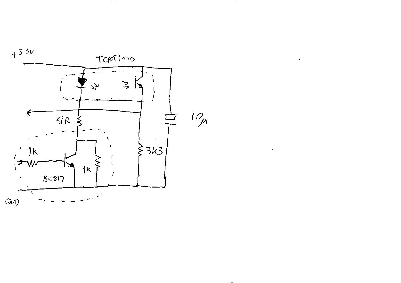
I've finalised my design for a modulated sensor hacked from the original one. The schematic is attached. The main change from my original design is the addition of the 1K resistor between the collector and emitter of the transistor. This causes the IR emitter to generate a small amount of light even when the modulation control signal is off. The purpose of this is to bias the phototransistor into the linear region even when there is very little ambient IR.
Adding this resistor has halved the residual sensitivity to ambient light. I can now go from no ambient IR to enough ambient IR to almost saturate the sensor when the IR is turned on, and the Z31 reading only goes up from 480 to 490. If I turn the modulation off, under the same conditions the reading goes up from 470 to 775. So the modulated sensor is 30 times less sensitive to ambient light than the unmodulated sensor. The change in reading from no light to bright light corresponds to a difference in nozzle height of just 0.05mm. I'm satisfied with this. All I need to do now is make sure I don't have direct sunlight on the white tapes when z-homing or running the bed compensation.
Edited 1 time(s). Last edit at 01/19/2014 03:52PM by dc42.
Large delta printer [miscsolutions.wordpress.com], E3D tool changer, Robotdigg SCARA printer, Crane Quad and Ormerod
Disclosure: I design Duet electronics and work on RepRapFirmware, [duet3d.com].

Sorry, only registered users may post in this forum.