Rebuilt the bottom Half
Posted by johneato
|
Re: Rebuilt the bottom Half January 28, 2014 04:19PM |
Registered: 10 years ago Posts: 147 |
|
Re: Rebuilt the bottom Half January 28, 2014 04:38PM |
Registered: 10 years ago Posts: 119 |
Quote
johneato
Paul
Yes its an early board, I need to sort it. A bit reluctant to do it at the moment as the system is very stable, none of the freezing I have read about on other threads.
John
Well looking at the datasheet for the U3 device "A4403" the FB pin should be around 0.88V but where the two resistors are fitted wrong that pin becomes floating (i.e. not connected to anything) and may not be 0.88V.
R60 and R61 act as a potential divider feeding FB a nice 0.8V.
It probably only working due to the USB ports feeding it the 5V
However I may be wrong due to never using that device.
Paul
RS Ormerod No 436
|
Re: Rebuilt the bottom Half January 28, 2014 04:41PM |
Registered: 10 years ago Posts: 119 |
Quote
PaulHam
Thanks John, that's cleared it up for me!
Perhaps ill give it a go in the future!
I see that you have had to bend the pin for the ir sensor too, I have a feeling mine will snap off !
Yeah I thought the same, I am so tempted in buying a 50pin IDC plug and connect that wire to pin 33 (I.e. the bent pin)
Paul
RS Ormerod No 436
|
Re: Rebuilt the bottom Half January 28, 2014 05:01PM |
Registered: 10 years ago Posts: 147 |
Yeah feels like overkill, a big connector for one pin.Quote
TMD_RS436
Quote
PaulHam
Thanks John, that's cleared it up for me!
Perhaps ill give it a go in the future!
I see that you have had to bend the pin for the ir sensor too, I have a feeling mine will snap off !
Yeah I thought the same, I am so tempted in buying a 50pin IDC plug and connect that wire to pin 33 (I.e. the bent pin)
Paul
Problem is I'm too scared to bend it back up now as I think it will snap
|
Re: Rebuilt the bottom Half January 28, 2014 05:10PM |
Registered: 10 years ago Posts: 14,672 |
Quote
TMD_RS436
Quote
PaulHam
Thanks John, that's cleared it up for me!
Perhaps ill give it a go in the future!
I see that you have had to bend the pin for the ir sensor too, I have a feeling mine will snap off !
Yeah I thought the same, I am so tempted in buying a 50pin IDC plug and connect that wire to pin 33 (I.e. the bent pin)
Paul
I put an extra connector at the bottom of the board for this connection (along with another one to support a modulated IR sensor), although my main reason for doing this was to reduce inductive noise pickup on the sensor wire from the switching regulator. See [forums.reprap.org].
Edited 1 time(s). Last edit at 01/28/2014 05:10PM by dc42.
Large delta printer [miscsolutions.wordpress.com], E3D tool changer, Robotdigg SCARA printer, Crane Quad and Ormerod
Disclosure: I design Duet electronics and work on RepRapFirmware, [duet3d.com].
|
Re: Rebuilt the bottom Half February 01, 2014 01:56PM |
Registered: 10 years ago Posts: 1,230 |
Quote
johneato
....However I do like the idea of doing away with the aluminium. I don’t know if that is a good idea, I would be interested to hear other peoples opinion.
John
Tried printing PLA at 60 degrees bed temperature without the aluminum plate, I see no difference there
Sanded the dents down with grain P400 that's why the surface of the kapton looks a bit dull
The aluminum plate now look a bit worried, it should be, I have a hacksaw and a cunning plan :-)
Erik
|
Re: Rebuilt the bottom Half February 01, 2014 03:12PM |
Registered: 10 years ago Posts: 132 |
|
Re: Rebuilt the bottom Half February 01, 2014 05:02PM |
Registered: 10 years ago Posts: 1,230 |
Quote
johneato
....I presume that the PCB is now bearing the weight of the glass and print. Have you done anything to reinforce the PCB corners.
John
Yes it is and no I haven't - yet
My plan is top down - 4mm glass, PCB and cork for the isolation, how the mounting will be I haven't decided yet, but it seems to me that the PCB will carry the weight just fine, well the carrying points is very close to the glass so really no big surprise there
Quote
..Before I throw the aluminium away have you tried it with ABS.
John
No, I'm not there yet, still on the PLA learning curve, but for the sake of testing the bed I took it to 110C at room temperature 25.1 (bed start ditto), I put a 200x200 6mm cardboard on top to reduce the heat loss at warm up
Alpine 550W, standard Ormerod wiring
09.45 - 25.1
09.55 - 100.0
09.57 - 110
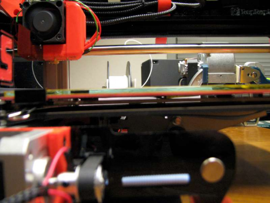
Here's a side shot of the bed and PCB, the picture is a bit fuzzy, but I hope you can see that the PCB don't hang at all (I moved the under-the-PCB-isolating cardboard down while taking the picture and put white paper behind)
Erik
Sorry, only registered users may post in this forum.


