Improvement to IR sensor mounting
Posted by dc42
|
Re: Improvement to IR sensor mounting February 03, 2014 01:01PM |
Registered: 10 years ago Posts: 132 |
|
Re: Improvement to IR sensor mounting February 03, 2014 01:03PM |
Registered: 10 years ago Posts: 14,672 |
John, please go ahead - I didn't want to assume you would do this one, in case you have had enough of me!
Large delta printer [miscsolutions.wordpress.com], E3D tool changer, Robotdigg SCARA printer, Crane Quad and Ormerod
Disclosure: I design Duet electronics and work on RepRapFirmware, [duet3d.com].
Large delta printer [miscsolutions.wordpress.com], E3D tool changer, Robotdigg SCARA printer, Crane Quad and Ormerod
Disclosure: I design Duet electronics and work on RepRapFirmware, [duet3d.com].
|
Re: Improvement to IR sensor mounting February 03, 2014 02:58PM |
Registered: 10 years ago Posts: 132 |
|
Re: Improvement to IR sensor mounting February 03, 2014 05:59PM |
Registered: 10 years ago Posts: 14,672 |
Wow, that was quick! It looks good in slic3r, and I'll print it tomorrow. Thanks!
Large delta printer [miscsolutions.wordpress.com], E3D tool changer, Robotdigg SCARA printer, Crane Quad and Ormerod
Disclosure: I design Duet electronics and work on RepRapFirmware, [duet3d.com].
Large delta printer [miscsolutions.wordpress.com], E3D tool changer, Robotdigg SCARA printer, Crane Quad and Ormerod
Disclosure: I design Duet electronics and work on RepRapFirmware, [duet3d.com].
|
Re: Improvement to IR sensor mounting February 05, 2014 11:38AM |
Registered: 10 years ago Posts: 14,672 |
John, the new z-motor mount works perfectly. Thanks!
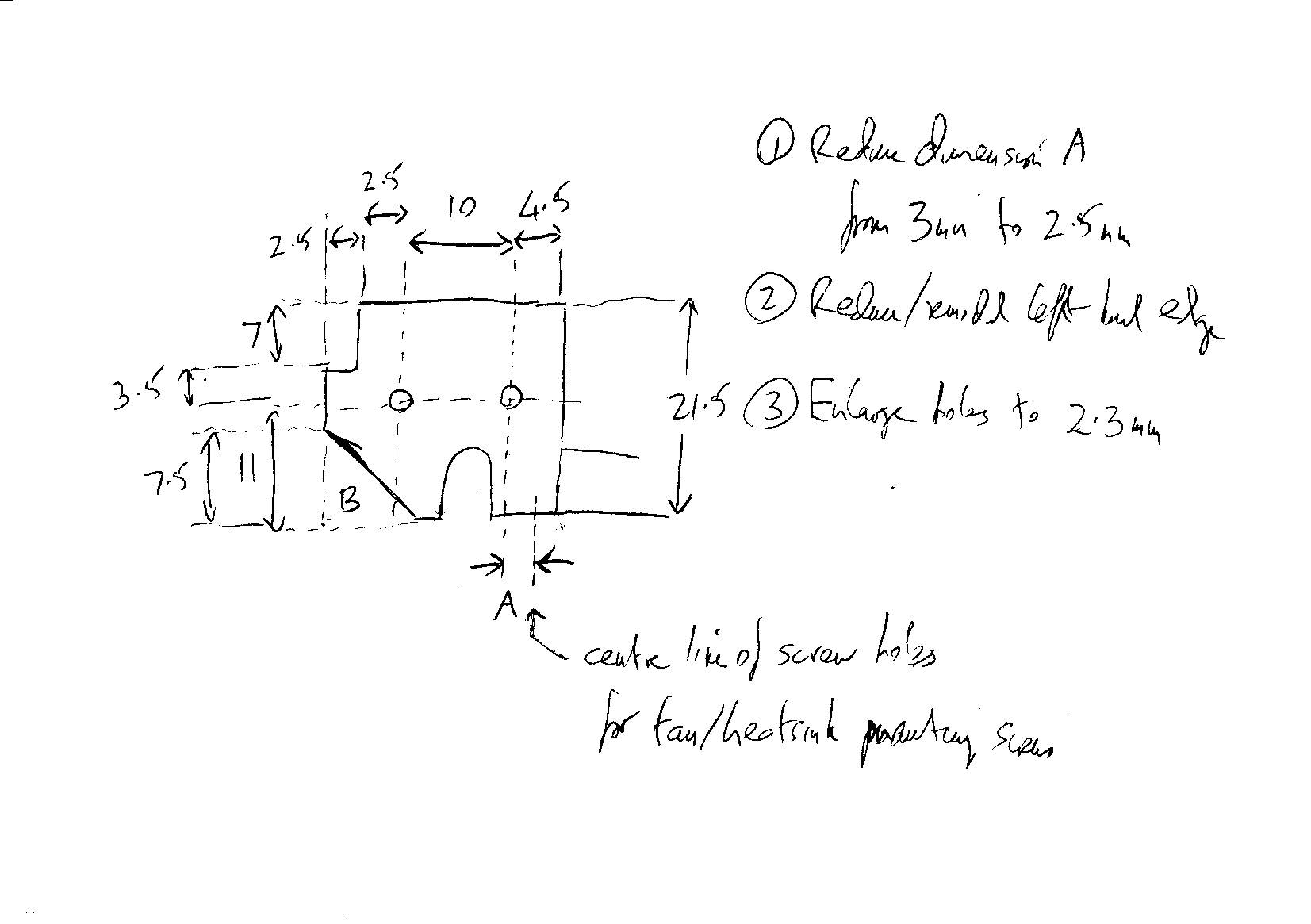
Unfortunately, the heatsink duct still isn't quite right. Could you possibly change it again? Here is a sketch of what I would like. The changes are:
1. Shift the whole piece you added right by 0.5mm, so that the offset between the rightmost of the 2 holes in the new piece and the heatsink screw holes in the original heatsink duct piece is reduced from the current 3mm to 2.5mm. This is to increase the sensor height above the nozzle by 0.5mm.
2. Trim the left hand side parts of the new piece to the dimensions shown. The changed dimensions are the two marked 2.5mm. Sorry, I don't know what they are in your current model because I have filed my print down to this size. This is to allow a little more room for the sensor head, and to make sure that the strengthening tab to the left of the leftmost hole doesn't protrude lower than the sensor head.
3. Optionally, remove the corner marked B in the diagram, to reduce print time and filament used.
4. Increase the two holes to 2.3mm diameter. I have established that this is a good size for the M3 screws to self-tap in them.
Thanks for all your help! I'll post some photos soon.
Edited 1 time(s). Last edit at 02/05/2014 11:40AM by dc42.
Large delta printer [miscsolutions.wordpress.com], E3D tool changer, Robotdigg SCARA printer, Crane Quad and Ormerod
Disclosure: I design Duet electronics and work on RepRapFirmware, [duet3d.com].
|
Re: Improvement to IR sensor mounting February 05, 2014 12:28PM |
Registered: 10 years ago Posts: 132 |
|
Re: Improvement to IR sensor mounting February 05, 2014 12:39PM |
Registered: 10 years ago Posts: 14,672 |
Hi John,
I guess my measurement or my print wasn't very accurate then. Please move it by 0.5mm, that is how far I want to raise the sensor head.
Here are some photos:
I just completed the thin-walled test piece using the new sensor mounting position, printing direct on glass, and letting the IR sensor do the z-homing and bed compensation (although I levelled the bed manually earlier today), and it came out perfectly.
David
Edited 2 time(s). Last edit at 02/05/2014 12:50PM by dc42.
Large delta printer [miscsolutions.wordpress.com], E3D tool changer, Robotdigg SCARA printer, Crane Quad and Ormerod
Disclosure: I design Duet electronics and work on RepRapFirmware, [duet3d.com].
I guess my measurement or my print wasn't very accurate then. Please move it by 0.5mm, that is how far I want to raise the sensor head.
Here are some photos:


I just completed the thin-walled test piece using the new sensor mounting position, printing direct on glass, and letting the IR sensor do the z-homing and bed compensation (although I levelled the bed manually earlier today), and it came out perfectly.
David
Edited 2 time(s). Last edit at 02/05/2014 12:50PM by dc42.
Large delta printer [miscsolutions.wordpress.com], E3D tool changer, Robotdigg SCARA printer, Crane Quad and Ormerod
Disclosure: I design Duet electronics and work on RepRapFirmware, [duet3d.com].
|
Re: Improvement to IR sensor mounting February 05, 2014 02:24PM |
Registered: 10 years ago Posts: 132 |
David
Find attached the latest version of the heatsink duct.
The photographs of the mod look good, I am keen to have a go at incorporating it.
Is this still the current modified circuit diagram? I've looked back on the forum but can't see any instructions on how to enable/disable the modulation.
Neither can I see which pin is used to drive the modulation. Did you have to adjust the homing parameters for X, to account for the displacement or did the two movements cancel each out.
John

|
Re: Improvement to IR sensor mounting February 05, 2014 04:43PM |
Registered: 10 years ago Posts: 14,672 |
John,
1. Yes that is still the circuit I am using for the modulated sensor. However, if I were building it again, I would reduce the 1K resistor between collector and emitter to about 470 ohms, because I think this will further reduce the sensitivity to ambient light.
2. The pin I am using to drive the modulation is the one directly above the one on the expansion connector that the IR sensor output is connected to. This means you can use a 2-pin connector. But I've added extra pins at the bottom of the board to connect the sensor to reduce noise pickup (see [forums.reprap.org]), although this is not essential. All recent versions of my firmware on the Duet branch of [github.com] support modulated sensors. You need to put M558 P2 in config.g to enable modulation instead of M558 P1. RRP has accepted my changes into the Duet branch of their firmware, but not yet into the master branch.
3. Yes I had to adjust the homez.g and homeall.g files. I changed the Z homing point from X55 to X40. In config.g I use X40 and X220 as the X offset for probe points, and I use Y0 and Y190.
PS - thanks for the modified design file! I almost didn't notice it
Edited 4 time(s). Last edit at 02/05/2014 04:55PM by dc42.
Large delta printer [miscsolutions.wordpress.com], E3D tool changer, Robotdigg SCARA printer, Crane Quad and Ormerod
Disclosure: I design Duet electronics and work on RepRapFirmware, [duet3d.com].
|
Re: Improvement to IR sensor mounting February 05, 2014 07:17PM |
Registered: 10 years ago Posts: 2,472 |
Quote
dc42
John,
1. Yes that is still the circuit I am using for the modulated sensor. However, if I were building it again, I would reduce the 1K resistor between collector and emitter to about 470 ohms, because I think this will further reduce the sensitivity to ambient light.
Not sure I understand your reasoning about that. Surely that resistor keeps the LED partially on all the time, reducing the difference between the "on" illumination and the "off" illumination, and reducing it will increase the "off" illumination reducing the difference? I would have thought no resistor at all would give the best effect - i.e. when switched off by the Duet, the LED is completely dark so you are only measuring ambient light. It's just past midnight so my brain is probably pumpkinified - what am I missing?
Dave
(#106)
|
Re: Improvement to IR sensor mounting February 05, 2014 07:34PM |
Registered: 10 years ago Posts: 14,672 |
Quote
dmould
Surely that resistor keeps the LED partially on all the time, reducing the difference between the "on" illumination and the "off" illumination, and reducing it will increase the "off" illumination reducing the difference? I would have thought no resistor at all would give the best effect - i.e. when switched off by the Duet, the LED is completely dark so you are only measuring ambient light.
If the phototransistor response was linear, then there would be no point in adding the resistor. However, the phototransistor is less sensitive at low light levels. Without the resistor, a small amount of ambient light causes a small amount of phototransistor current when the IR emitter is off, but a much larger increase in phototransistor current when the IR emitter is on. [I recall that in one test, turning an incandescent light on increased the G31 reading by 6 when the IR emitter was off, but by 20 when it was on.] This makes the difference between on-current and off-current depend on the ambient light. With the resistor added, the IR emitter biases the phototransistor out of the less sensitive low-light regime.
Without the resistor, in my tests the sensitivity of the modulated sensor to bright ambient light was reduced by a factor of 15 compared to an unmodulated sensor. With a 1K resistor, the sensitivity to the distance of the white tape is reduced by about 5%, but the effect of ambient light is decreased by a further factor of 2, making it 30 times less sensitive than an unmodulated sensor. I'm guessing that if the resistor is decreased to 470 ohms, the further 5% loss in sensitivity will be more than compensated by a further reduction in sensitivity to ambient light.
Edited 1 time(s). Last edit at 02/05/2014 07:37PM by dc42.
Large delta printer [miscsolutions.wordpress.com], E3D tool changer, Robotdigg SCARA printer, Crane Quad and Ormerod
Disclosure: I design Duet electronics and work on RepRapFirmware, [duet3d.com].
|
Re: Improvement to IR sensor mounting February 06, 2014 07:43AM |
Registered: 10 years ago Posts: 2,472 |
OK, understood, that makes sense now. So it's the equivalent to providing a base bias current to bring a transistor into its region of greatest amplification - if you had access to the base of the phototransistor you might have been able to achieve it that way instead. Next time I take my Ormerod apart to make modifications I will be making your modulated IR mod, but I also intend to fit a white LED strip under the heatsink cover to provide illumination for the print, as suggested elsewhere. I suspect that this fixed illuminator might achieve the same thing and obviate the need for the resistor.
Dave
(#106)
Dave
(#106)
|
Re: Improvement to IR sensor mounting February 06, 2014 08:20AM |
Registered: 10 years ago Posts: 14,672 |
Quote
dmould
I also intend to fit a white LED strip under the heatsink cover to provide illumination for the print, as suggested elsewhere. I suspect that this fixed illuminator might achieve the same thing and obviate the need for the resistor.
I doubt it - visible LED lighting does not produce a significant amount of IR.
Large delta printer [miscsolutions.wordpress.com], E3D tool changer, Robotdigg SCARA printer, Crane Quad and Ormerod
Disclosure: I design Duet electronics and work on RepRapFirmware, [duet3d.com].
|
Re: Improvement to IR sensor mounting February 06, 2014 08:41AM |
Registered: 10 years ago Posts: 2,472 |
Quote
dc42
Quote
dmould
I also intend to fit a white LED strip under the heatsink cover to provide illumination for the print, as suggested elsewhere. I suspect that this fixed illuminator might achieve the same thing and obviate the need for the resistor.
I doubt it - visible LED lighting does not produce a significant amount of IR.
Does the phototransistor only respond to IR? I would have thought it should, having IR filters, but I have noticed that my LED inspection light affects the reading, so I'm not too sure about that ... Anyway, I could always put an IR LED in the strip - just thinking that biasing the IR LED on the probe subtracts from the amount of on/off difference it can produce, so a separate bias source would be better if it can be easily arranged.
Dave
(#106)
|
Re: Improvement to IR sensor mounting February 06, 2014 09:10AM |
Registered: 10 years ago Posts: 14,672 |
I have a 7W LED spotlight above my Ormerod, and it doesn't affect the sensor readings significantly. Biasing the IR LED does reduce the amount of on/off difference it can produce, but only by about 5% using a 1K resistor, or 10% using a 470 ohm resistor.
Large delta printer [miscsolutions.wordpress.com], E3D tool changer, Robotdigg SCARA printer, Crane Quad and Ormerod
Disclosure: I design Duet electronics and work on RepRapFirmware, [duet3d.com].
Large delta printer [miscsolutions.wordpress.com], E3D tool changer, Robotdigg SCARA printer, Crane Quad and Ormerod
Disclosure: I design Duet electronics and work on RepRapFirmware, [duet3d.com].
|
Re: Improvement to IR sensor mounting February 06, 2014 10:37AM |
Registered: 10 years ago Posts: 14,672 |
@johneato,
Sorry, the part still isn't right. In item (2) in my message [forums.reprap.org] and in the drawing I attached, there were two dimensions reduced to 2.5mm, and you have only reduced one of them. So the part I printed from your latest STL file sticks out about 2mm too far on the left hand side as printed.
Large delta printer [miscsolutions.wordpress.com], E3D tool changer, Robotdigg SCARA printer, Crane Quad and Ormerod
Disclosure: I design Duet electronics and work on RepRapFirmware, [duet3d.com].
|
Re: Improvement to IR sensor mounting February 07, 2014 07:02AM |
Registered: 10 years ago Posts: 132 |
dc42
Sorry about the delay in getting back to you, for some reason I never noticed your post. Neither did I notice that second change.
Find attached the next version.
Rather than butcher the existing IR board I have ordered the bits to build a new board, I've added a 0.1uf across the supply.
John
Sorry about the delay in getting back to you, for some reason I never noticed your post. Neither did I notice that second change.
Find attached the next version.
Rather than butcher the existing IR board I have ordered the bits to build a new board, I've added a 0.1uf across the supply.
John
|
Re: Improvement to IR sensor mounting February 07, 2014 07:19AM |
Registered: 10 years ago Posts: 14,672 |
Thanks John, that one looks good!
I'm considering designing a new, larger pcb for the modulated IR sensor. The pcb would also feature a reliable and more easily dismantled connector for connecting all the hot end parts, and one or more LEDs to illuminate the print.
Large delta printer [miscsolutions.wordpress.com], E3D tool changer, Robotdigg SCARA printer, Crane Quad and Ormerod
Disclosure: I design Duet electronics and work on RepRapFirmware, [duet3d.com].
|
Re: Improvement to IR sensor mounting February 07, 2014 07:34AM |
Registered: 10 years ago Posts: 147 |
Quote
dc42
Thanks John, that one looks good!
I'm considering designing a new, larger pcb for the modulated IR sensor. The pcb would also feature a reliable and more easily dismantled connector for connecting all the hot end parts, and one or more LEDs to illuminate the print.
I'm Interested in that if you come to selling them
|
Re: Improvement to IR sensor mounting February 07, 2014 01:44PM |
Registered: 10 years ago Posts: 14,672 |
Quote
PaulHam
Quote
dc42
Thanks John, that one looks good!
I'm considering designing a new, larger pcb for the modulated IR sensor. The pcb would also feature a reliable and more easily dismantled connector for connecting all the hot end parts, and one or more LEDs to illuminate the print.
John, do you think the pcb should stick to my original modulated IR sensor design (so you need to run another wire back to the Duet), or should I put an attiny processor on it to do the modulation and emulate the unmodulated sensor?
Large delta printer [miscsolutions.wordpress.com], E3D tool changer, Robotdigg SCARA printer, Crane Quad and Ormerod
Disclosure: I design Duet electronics and work on RepRapFirmware, [duet3d.com].
|
Re: Improvement to IR sensor mounting February 07, 2014 09:58PM |
Registered: 10 years ago Posts: 119 |
Quote
dc42
Quote
PaulHam
Quote
dc42
Thanks John, that one looks good!
I'm considering designing a new, larger pcb for the modulated IR sensor. The pcb would also feature a reliable and more easily dismantled connector for connecting all the hot end parts, and one or more LEDs to illuminate the print.
John, do you think the pcb should stick to my original modulated IR sensor design (so you need to run another wire back to the Duet), or should I put an attiny processor on it to do the modulation and emulate the unmodulated sensor?
Well I have been ill for the last week or so, so I haven't been around much and read all posts, but if your intending to add stuff like a LED or two etc then it wouldn't hurt adding a attiny controller to control everything on that PCB, then you could use a SW version of SPI (if available) to talk between the Duet and the attiny controller, using SW version of SPI will allow us to use any 3 pins for the RD, WR and CLK.
This would also allow to add new stuff to that new PCB without the need to change the cable loom etc.
Paul
Edited 1 time(s). Last edit at 02/07/2014 09:58PM by TMD_RS436.
RS Ormerod No 436
|
Re: Improvement to IR sensor mounting February 08, 2014 06:08AM |
Registered: 10 years ago Posts: 132 |
Presumably you are trying to reduce noise by adding the attiny processor, is the noise still a problem with your latest design.So not sure what you are going to gain in performance, maybe some additional functionality. I'll continue to make my PCB from your current design. I'm going to make up a new loom with the additional wire, 4 way header one end and 2 x 2 way headers on the other end, keeping it compatable with the current sensor. At least if you go ahead with the addional processor I will have something to measure it against.Quote
dc42
John, do you think the pcb should stick to my original modulated IR sensor design (so you need to run another wire back to the Duet), or should I put an attiny processor on it to do the modulation and emulate the unmodulated sensor?
John
|
Re: Improvement to IR sensor mounting February 08, 2014 06:18AM |
Registered: 10 years ago Posts: 14,672 |
I think I'll make the pcb so that you can populate it either with my original modulated sensor design or with the attiny. The main reason for using the attiny would be so that the board can use the original 3-wire loom. Noise is not a serious problem with the modulated sensor design, although I did add extra pins at the bottom of the Duet board to halve the noise pickup from the switching regulator (see the thread on the modulated IR sensor). The attiny would make it easy to use a higher modulation frequency, which would reduce the [already very small] sensitivity to 50Hz modulation from bright incandescent light.
Your latest heatsink duct design is working well and puts the sensor head at just the right height. The right-hand hole didn't seem to be deep enough (it needs to be 4mm), but no worries, I drilled it a bit deeper.
Edited 1 time(s). Last edit at 02/08/2014 06:20AM by dc42.
Large delta printer [miscsolutions.wordpress.com], E3D tool changer, Robotdigg SCARA printer, Crane Quad and Ormerod
Disclosure: I design Duet electronics and work on RepRapFirmware, [duet3d.com].
|
Re: Improvement to IR sensor mounting February 08, 2014 10:42AM |
Registered: 10 years ago Posts: 14,672 |
I just had another idea for the hotend pcb. If I put an attiny45 processor on it, not only can I use it to do the sensor modulation, I can also use it to monitor the hotend thermistor and/or heater, and turn the fan off when the printer is cold and idle.
Large delta printer [miscsolutions.wordpress.com], E3D tool changer, Robotdigg SCARA printer, Crane Quad and Ormerod
Disclosure: I design Duet electronics and work on RepRapFirmware, [duet3d.com].
Large delta printer [miscsolutions.wordpress.com], E3D tool changer, Robotdigg SCARA printer, Crane Quad and Ormerod
Disclosure: I design Duet electronics and work on RepRapFirmware, [duet3d.com].

Sorry, only registered users may post in this forum.