Improvement to IR sensor mounting
Posted by dc42
|
Improvement to IR sensor mounting January 30, 2014 02:09PM |
Registered: 10 years ago Posts: 14,672 |
I'm looking to change the mounting position of the IR sensor. Currently, it isn't in line with the nozzle, and it is mounted on the x-carriage rather than the hotend. This has two adverse consequences:
1. Any change in the amount of head sag affects the relative heights of the nozzle and IR sensor.
2. Any movement between the hotend and the x-carriage (e.g. due to thermal expansion in the nozzle mount system) affects the relative heights of the nozzle and IR sensor.
So I would like to mount the IR sensor on the hotend assembly, in such a way that the sensor head is line with the nozzle along the x-axis. In order to avoid fouling the threaded rod, it is probably best to rotate the sensor board by 90 degrees, bearing in mind that the sensor head is not central at the bottom of the board, so the board will need to be offset sideways.
My expertise is electronics and software, not 3D design. Would anyone be kind enough to volunteer to design a new printed heatsink duct with fixings for the sensor board? I can do a new sensor PCB if necessary, but it would be better to accommodate the existing IR sensor board if possible.
The only disadvantage I can see to this arrangement is that a user who has more than one hotend (e.g. one for PLA and another for ABS) would also need more than one sensor board.
Large delta printer [miscsolutions.wordpress.com], E3D tool changer, Robotdigg SCARA printer, Crane Quad and Ormerod
Disclosure: I design Duet electronics and work on RepRapFirmware, [duet3d.com].
|
Re: Improvement to IR sensor mounting January 30, 2014 04:12PM |
Registered: 10 years ago Posts: 132 |
|
Re: Improvement to IR sensor mounting January 31, 2014 04:04AM |
Registered: 10 years ago Posts: 132 |
|
Re: Improvement to IR sensor mounting January 31, 2014 04:42AM |
Registered: 10 years ago Posts: 14,672 |
Quote
johneato
dc42
I'm not sure I understand your suggested design.The nozzle is extremely close to being in line with the threaded rod, so I can't see how to place the sensor in line with the nozzle, miss the threaded rod and still be able activate the X home.
John
The x-homing tab will need to be extended. So that's another printed part that will need to be modified, although temporarily I will just glue a piece of white card on it. By rotating the sensor 90 degrees, the sensor board will protrude only 8mm beyond the heatsink duct in the -X direction, leaving enough clearance from the threaded rod.
Last night I printed a part to test this out:

The idea is that the sensor board it attached over the lower rectangle using the two screw holes, then the upper rectangle is attached with double sided sticky tape on to the bottom left corner of the face of the heatsink duct that faces the -X direction.
If this works, then I will probably design a new sensor pcb that is taller and wider. At the top I will put a locking connector for all the hotend and sensor wires, with pads on the pcb to solder the fan, thermistor and heater wires to. I don't like the existing 6-way connector, the thermistor pins have lost contact a few times and I can't get the crimp pins/sockets out of the housing. Also the existing sensor connector does not lock and tends to come apart.
Edited 2 time(s). Last edit at 01/31/2014 04:47AM by dc42.
Large delta printer [miscsolutions.wordpress.com], E3D tool changer, Robotdigg SCARA printer, Crane Quad and Ormerod
Disclosure: I design Duet electronics and work on RepRapFirmware, [duet3d.com].
|
Re: Improvement to IR sensor mounting January 31, 2014 05:27AM |
Registered: 10 years ago Posts: 132 |
|
Re: Improvement to IR sensor mounting January 31, 2014 05:49AM |
Registered: 10 years ago Posts: 14,672 |
Quote
johneato
Send me the STL of your new surface mount and I will graft it onto the heatsink duct
John
PS Just found your software change that stops an axis overrunning. Brilliant
Thanks, here are the STL and OpenScad files. You will have to omit the left hand part of the lower tab because that would protrude below the base of the original duct, making it unprintable. Also you can omit most of the top tab because I only included it to make alignment and attaching easier. The hole centres will be 2.5mm above the base (as printed) of the part.
Re my software change, if you are using 57f then I advise you to upgrade to 57g here [dl.dropboxusercontent.com].
Large delta printer [miscsolutions.wordpress.com], E3D tool changer, Robotdigg SCARA printer, Crane Quad and Ormerod
Disclosure: I design Duet electronics and work on RepRapFirmware, [duet3d.com].
|
Re: Improvement to IR sensor mounting January 31, 2014 08:27AM |
Registered: 10 years ago Posts: 132 |
|
Re: Improvement to IR sensor mounting January 31, 2014 08:54AM |
Registered: 10 years ago Posts: 14,672 |
Yes, that looks the correct placement to me. My earlier comments were wrong, I was assuming that the duct was printed the other way up. As it stands there is a large overhang. The bit under the overhang could be filled in, with a large hole included to pass the thermistor wire through.
Large delta printer [miscsolutions.wordpress.com], E3D tool changer, Robotdigg SCARA printer, Crane Quad and Ormerod
Disclosure: I design Duet electronics and work on RepRapFirmware, [duet3d.com].
Large delta printer [miscsolutions.wordpress.com], E3D tool changer, Robotdigg SCARA printer, Crane Quad and Ormerod
Disclosure: I design Duet electronics and work on RepRapFirmware, [duet3d.com].
|
Re: Improvement to IR sensor mounting January 31, 2014 08:57AM |
Registered: 10 years ago Posts: 2,472 |
|
Re: Improvement to IR sensor mounting January 31, 2014 09:05AM |
Registered: 10 years ago Posts: 132 |
|
Re: Improvement to IR sensor mounting January 31, 2014 09:11AM |
Registered: 10 years ago Posts: 14,672 |
The screws are 5mm long so after going through the pcb there is less than 4mm to thread into the plastic. That's why my stick-on plastic piece was 4mm thick.
Large delta printer [miscsolutions.wordpress.com], E3D tool changer, Robotdigg SCARA printer, Crane Quad and Ormerod
Disclosure: I design Duet electronics and work on RepRapFirmware, [duet3d.com].
Large delta printer [miscsolutions.wordpress.com], E3D tool changer, Robotdigg SCARA printer, Crane Quad and Ormerod
Disclosure: I design Duet electronics and work on RepRapFirmware, [duet3d.com].
|
Re: Improvement to IR sensor mounting January 31, 2014 09:18AM |
Registered: 10 years ago Posts: 14,672 |
I just found that my printed part needs another bit cut out of it for the connector, so don't bother tidying up your design yet!
Large delta printer [miscsolutions.wordpress.com], E3D tool changer, Robotdigg SCARA printer, Crane Quad and Ormerod
Disclosure: I design Duet electronics and work on RepRapFirmware, [duet3d.com].
Large delta printer [miscsolutions.wordpress.com], E3D tool changer, Robotdigg SCARA printer, Crane Quad and Ormerod
Disclosure: I design Duet electronics and work on RepRapFirmware, [duet3d.com].
|
Re: Improvement to IR sensor mounting January 31, 2014 09:57AM |
Registered: 10 years ago Posts: 132 |
|
Re: Improvement to IR sensor mounting January 31, 2014 09:59AM |
Registered: 10 years ago Posts: 176 |
|
Re: Improvement to IR sensor mounting January 31, 2014 10:46AM |
Registered: 10 years ago Posts: 14,672 |
Quote
johneato
dc42
I have tidied the design and included a cutout for the connector. Let me know if it is not correct.
John
John, that looks good. Perhaps make the hole for the thermistor wire a little larger.
Tru168, that can be fixed by extending the homing tab around the front of the threaded rod. I'll glue a piece of white card on the existing homing tab for testing, but as a permanent solution, the z-carriage design could be modified.
Large delta printer [miscsolutions.wordpress.com], E3D tool changer, Robotdigg SCARA printer, Crane Quad and Ormerod
Disclosure: I design Duet electronics and work on RepRapFirmware, [duet3d.com].
|
Re: Improvement to IR sensor mounting January 31, 2014 11:01AM |
Registered: 10 years ago Posts: 132 |
|
Re: Improvement to IR sensor mounting January 31, 2014 12:34PM |
Registered: 10 years ago Posts: 14,672 |
Thanks John, I'll print it when my current print has finished. I agree the connector is insecure, I've been meaning to solder ir for a while now. But the connector is convenient for testing this mod. Had I thought about it a bit more, I could have asked for a slot instead of a hole.
Large delta printer [miscsolutions.wordpress.com], E3D tool changer, Robotdigg SCARA printer, Crane Quad and Ormerod
Disclosure: I design Duet electronics and work on RepRapFirmware, [duet3d.com].
Large delta printer [miscsolutions.wordpress.com], E3D tool changer, Robotdigg SCARA printer, Crane Quad and Ormerod
Disclosure: I design Duet electronics and work on RepRapFirmware, [duet3d.com].
|
Re: Improvement to IR sensor mounting January 31, 2014 01:10PM |
Registered: 10 years ago Posts: 132 |
|
Re: Improvement to IR sensor mounting January 31, 2014 01:17PM |
Registered: 10 years ago Posts: 14,672 |
Quote
johneato
I had alrerady thought of that too, heres the slot
John
Great, I'll go with that one!
As a matter of interest, what program are you using to import and modify the .dxf file provided by RRP?
Large delta printer [miscsolutions.wordpress.com], E3D tool changer, Robotdigg SCARA printer, Crane Quad and Ormerod
Disclosure: I design Duet electronics and work on RepRapFirmware, [duet3d.com].
|
Re: Improvement to IR sensor mounting January 31, 2014 01:34PM |
Registered: 10 years ago Posts: 132 |
I am using TurboCad it is a paid for product, not stupid money but I find it very good. It has a long list of compatable formats for import and export. I've used it for a couple of years on my CNC so its made the learning curve for 3D printing a lot easier. I think you meant RRP stl and not dxf
John
John
|
Re: Improvement to IR sensor mounting February 01, 2014 06:08PM |
Registered: 10 years ago Posts: 14,672 |
John, thanks very much for your help so far. I have printed the new heatsink duct and installed it, with the sensor on it. It's working, but could do with a few tweaks if you have time. With the duct lying on its base as printed, so the new slot for the thermistor wire is at the bottom and facing you:
- Shift the new piece (including the holes) right 0.5mm
- Shave 0.5mm off the bottom of the new piece, then drop the new piece (including the holes) down 0.5mm
- Increase the thickness of the new piece by 1mm (otherwise there isn't enough room for the connector)
- Extend the piece to the left by 3mm, but to a height 7mm lower than the rest. This bit is to add extra strength to the left-hand hole - it's a bit close to the left hand edge, so when I drove the screw in it split along the layers.
Thanks - dc42
Large delta printer [miscsolutions.wordpress.com], E3D tool changer, Robotdigg SCARA printer, Crane Quad and Ormerod
Disclosure: I design Duet electronics and work on RepRapFirmware, [duet3d.com].
|
Re: Improvement to IR sensor mounting February 02, 2014 05:12AM |
Registered: 10 years ago Posts: 132 |
|
Re: Improvement to IR sensor mounting February 02, 2014 05:45AM |
Registered: 10 years ago Posts: 14,672 |
John, that looks good when I view it in slic3r except that the extra tab on the left hand side looks too high. It needs to be 7mm lower than the rest to provide room for the IR sensor head, and slic3r says the total height is 21.61mm. Can you confirm that the height of that new tab is about 14.6mm?
Large delta printer [miscsolutions.wordpress.com], E3D tool changer, Robotdigg SCARA printer, Crane Quad and Ormerod
Disclosure: I design Duet electronics and work on RepRapFirmware, [duet3d.com].
Large delta printer [miscsolutions.wordpress.com], E3D tool changer, Robotdigg SCARA printer, Crane Quad and Ormerod
Disclosure: I design Duet electronics and work on RepRapFirmware, [duet3d.com].
|
Re: Improvement to IR sensor mounting February 02, 2014 07:26AM |
Registered: 10 years ago Posts: 132 |
|
Re: Improvement to IR sensor mounting February 03, 2014 06:51AM |
Registered: 10 years ago Posts: 14,672 |
Sorry John, that's not what I meant. Version 3 was what I was after, with an extra tab on the left that is lower than the rest of the added material. It's just that this extra tab on the left looks a little too high when I view it in slic3er. It needs to be 7mm shorter than the rest of the added bit. Imagine an ant that walks into the left hand side of the added bit, and assume for a moment that the corners are square instead of the nice rounded ones you have done. The ant first has to walk up about 14mm, then walk along 3mm, then walk up exactly 7mm, which puts it at the top.
Large delta printer [miscsolutions.wordpress.com], E3D tool changer, Robotdigg SCARA printer, Crane Quad and Ormerod
Disclosure: I design Duet electronics and work on RepRapFirmware, [duet3d.com].
Large delta printer [miscsolutions.wordpress.com], E3D tool changer, Robotdigg SCARA printer, Crane Quad and Ormerod
Disclosure: I design Duet electronics and work on RepRapFirmware, [duet3d.com].
|
Re: Improvement to IR sensor mounting February 03, 2014 08:46AM |
Registered: 10 years ago Posts: 132 |
|
Re: Improvement to IR sensor mounting February 03, 2014 09:36AM |
Registered: 10 years ago Posts: 14,672 |
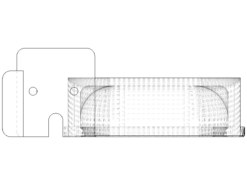
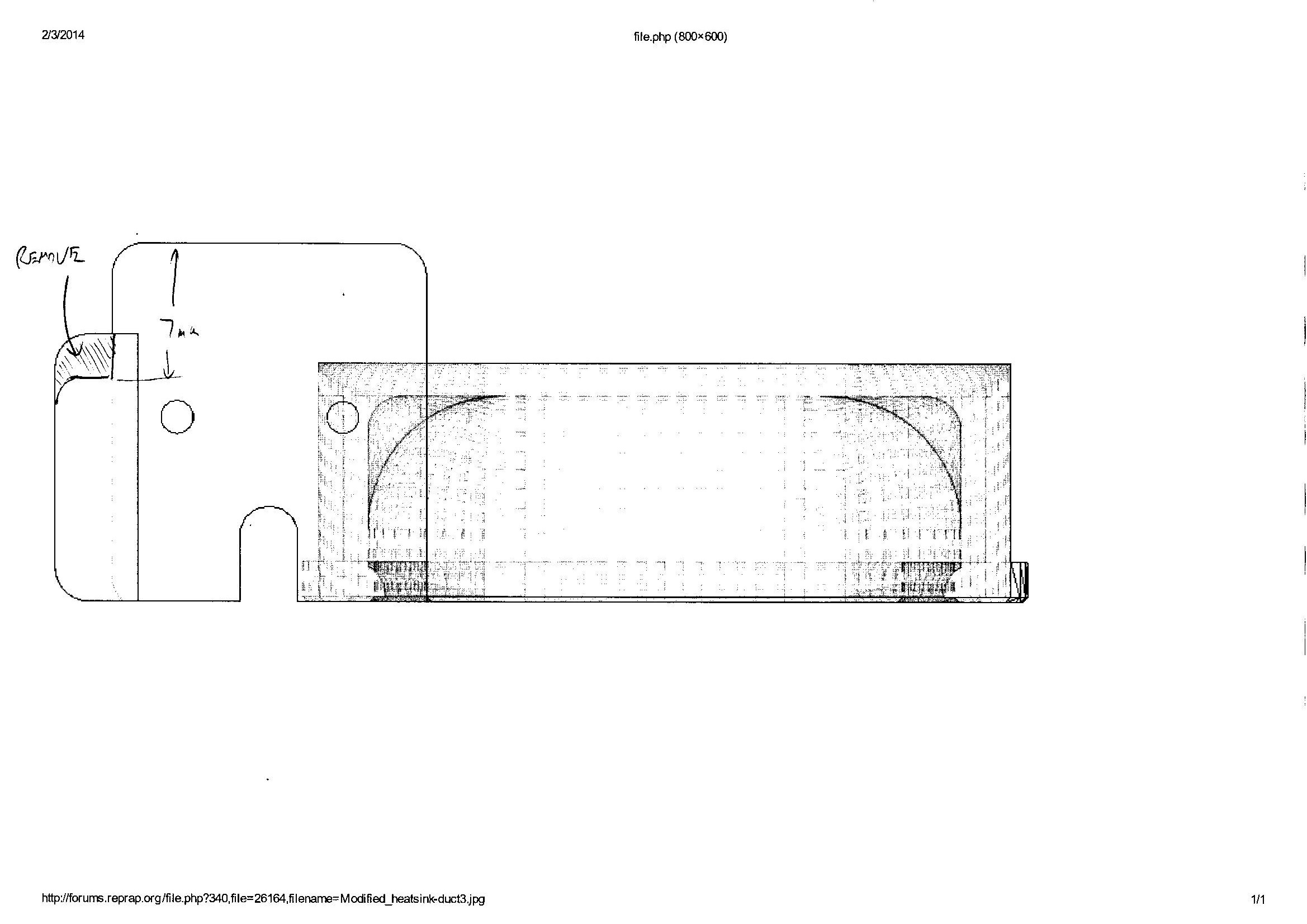
Thanks for that, here's a scan of that with my change marked. The only change I'm requesting from V3 is that the shaded area be removed so that there is 7mm clearance from the top of the part, so that the sensor head will fit.
Large delta printer [miscsolutions.wordpress.com], E3D tool changer, Robotdigg SCARA printer, Crane Quad and Ormerod
Disclosure: I design Duet electronics and work on RepRapFirmware, [duet3d.com].
Large delta printer [miscsolutions.wordpress.com], E3D tool changer, Robotdigg SCARA printer, Crane Quad and Ormerod
Disclosure: I design Duet electronics and work on RepRapFirmware, [duet3d.com].
|
Re: Improvement to IR sensor mounting February 03, 2014 10:12AM |
Registered: 10 years ago Posts: 132 |
|
Re: Improvement to IR sensor mounting February 03, 2014 10:19AM |
Registered: 10 years ago Posts: 14,672 |
John, I'm sorry to have wasted your time by not providing a picture. But version 5 looks just right - I'll go ahead and print it. Thanks!
Large delta printer [miscsolutions.wordpress.com], E3D tool changer, Robotdigg SCARA printer, Crane Quad and Ormerod
Disclosure: I design Duet electronics and work on RepRapFirmware, [duet3d.com].
Large delta printer [miscsolutions.wordpress.com], E3D tool changer, Robotdigg SCARA printer, Crane Quad and Ormerod
Disclosure: I design Duet electronics and work on RepRapFirmware, [duet3d.com].
|
Re: Improvement to IR sensor mounting February 03, 2014 12:54PM |
Registered: 10 years ago Posts: 14,672 |
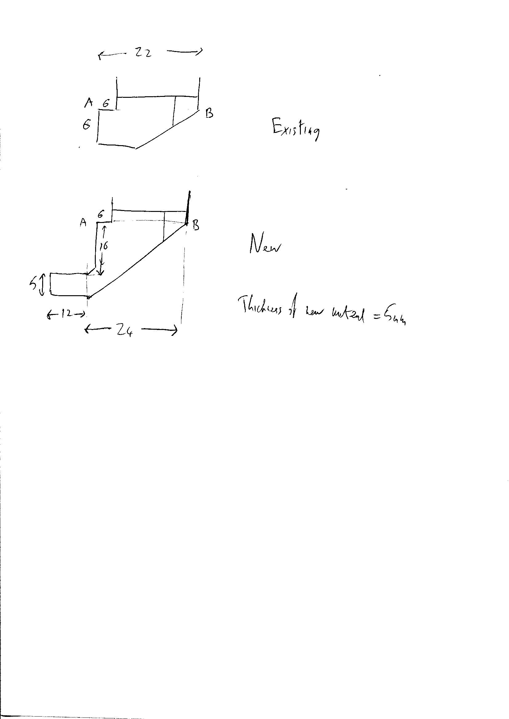
The other part I need to get this working reliably is a z-carriage modified to have a larger homing tab. Are there any volunteers to do this change? I've attached a drawing of the existing homing tab and the change needed. Points A and B are the same in both diagrams, I've marked then to define the location of the new tab relative to the old one.
Large delta printer [miscsolutions.wordpress.com], E3D tool changer, Robotdigg SCARA printer, Crane Quad and Ormerod
Disclosure: I design Duet electronics and work on RepRapFirmware, [duet3d.com].
Large delta printer [miscsolutions.wordpress.com], E3D tool changer, Robotdigg SCARA printer, Crane Quad and Ormerod
Disclosure: I design Duet electronics and work on RepRapFirmware, [duet3d.com].

Sorry, only registered users may post in this forum.