Why 0.24mm layer thickness?
Posted by Flyskyhy
|
Why 0.24mm layer thickness? February 20, 2014 01:03PM |
Registered: 10 years ago Posts: 48 |
I was wondering why the default and recommended settings for layer thickness are 0.24mm. That is pretty awkward when your CAD model measurements are in metric units - how many layers in a 3 mm thick sheet? Is there any disadvantage in setting that to 0.25mm instead?
Thanks,
René
Edited 1 time(s). Last edit at 02/20/2014 01:04PM by Flyskyhy.
Thanks,
René
Edited 1 time(s). Last edit at 02/20/2014 01:04PM by Flyskyhy.
|
Re: Why 0.24mm layer thickness? February 20, 2014 01:21PM |
Registered: 10 years ago Posts: 14,672 |
I can's see any problem with that. The Z axis step rate is 4000 steps/mm, so both 0.24 and 0.25mm are an exact number of steps (960 and 1000 respectively).
Large delta printer [miscsolutions.wordpress.com], E3D tool changer, Robotdigg SCARA printer, Crane Quad and Ormerod
Disclosure: I design Duet electronics and work on RepRapFirmware, [duet3d.com].
Large delta printer [miscsolutions.wordpress.com], E3D tool changer, Robotdigg SCARA printer, Crane Quad and Ormerod
Disclosure: I design Duet electronics and work on RepRapFirmware, [duet3d.com].
|
Re: Why 0.24mm layer thickness? February 20, 2014 01:45PM |
Registered: 10 years ago Posts: 2,472 |
It is best if the layer thickness is a whole number of steps of the Z axis stepper motor, otherwise the part must be printed with layers of different thicknesses that average out to the set layer height. My guess is that 0.24mm was chosen because it was a whole number of steps on a particular printer (e.g. a printer with a Z step size of .06mm) . However if I understand correctly, the Ormerod Z axis has a Z step size of 0.00025 mm (4000 steps/mm), so no reason not to make the layer height 0.25 mm (exactly 1000 steps). You've got me thinking, and I'll try slicing my next print with that layer height so I get exactly 4 layers to the mm. The X and Y axis each have 87 steps to the mm. I assume that the firmware does not accumulate rounding errors in its mm to steps conversion (though if it does, that could be the reason for some parts not having a very good size tolerance).
Dave
(#106)
Dave
(#106)
|
Re: Why 0.24mm layer thickness? February 20, 2014 04:54PM |
Registered: 10 years ago Posts: 578 |
Dave and dc42 - the "steps" that we set are microsteps (of which there are 16 to the step - these help with ramping acceleration, rather than final resting place) - the native step resolution for Z is 4 microns (rather than a 1/4), the default 0.24mm is 60 full steps. Possibly one reason for the default 0.24 was that the Ormerod was incapable of moving Z less than this during printing (until I finally convinced dc42 that this was the case and he fixed it, and I tried 0.12 with some success) - markbee continued halving from 0.24 and ran into trouble around 6 (I think) - I suggested at the time he try 4 or 8 but not sure if he did. Although the motors will try to turn to partial positions, they can't hold that position comfortably.
Flyskyhy - try multiples of 0.04mm instead (eg 0.20 and 0.40 if you like your decimals neat )
)
Thez x and y steps are set in platform.h with more precision than they're reported to when queried by gcodes (which is odd, since most have more trailing zeroes than they need - eg temperaratures):
I had a senior moment a couple of weeks ago based on that - I decided to replace my Y axis drive (and maybe X and Z) and bought a job lot of of 2mm pitch lead screw - I got round to cutting a length for Y today, turning down one end to mount in a bearing and making an acetal nut, then hooked it up to a spare motor and connected it to the duet, only to realise I was out by the same factor of 16 that tripped you - with that lead screw, the motor can't run fast enough to do anything other than 20 (or so) mm/s without losing torque and twitching (which is pretty much the firmware problem with the Z originally I think) - PAH!
Nonetheless, racks and pinions are pretty cheap, and I'm heading that way to see if I can get a rounder number of pulses per mm
CHeers
Ray
Edited 2 time(s). Last edit at 02/20/2014 05:00PM by rayhicks.
Flyskyhy - try multiples of 0.04mm instead (eg 0.20 and 0.40 if you like your decimals neat
) The
#define DRIVE_STEPS_PER_UNIT {87.4890, 87.4890, 4000.0, 420.0}
I had a senior moment a couple of weeks ago based on that - I decided to replace my Y axis drive (and maybe X and Z) and bought a job lot of of 2mm pitch lead screw - I got round to cutting a length for Y today, turning down one end to mount in a bearing and making an acetal nut, then hooked it up to a spare motor and connected it to the duet, only to realise I was out by the same factor of 16 that tripped you - with that lead screw, the motor can't run fast enough to do anything other than 20 (or so) mm/s without losing torque and twitching (which is pretty much the firmware problem with the Z originally I think) - PAH!
Nonetheless, racks and pinions are pretty cheap, and I'm heading that way to see if I can get a rounder number of pulses per mm
CHeers
Ray
Edited 2 time(s). Last edit at 02/20/2014 05:00PM by rayhicks.
|
Re: Why 0.24mm layer thickness? February 20, 2014 05:52PM |
Registered: 10 years ago Posts: 14,672 |
Ray, yes the steps are microsteps, however I don't see that it makes any difference. I am fairly sure there is nothing in the firmware that forces the Z stepper to stop on a full step when you home Z. The only reason I can see to make the layer height a full number of steps is if the microsteps are not all of equal size - but if that were the case, it would affect the X and Y axes much more because they have fewer steps/mm..
Large delta printer [miscsolutions.wordpress.com], E3D tool changer, Robotdigg SCARA printer, Crane Quad and Ormerod
Disclosure: I design Duet electronics and work on RepRapFirmware, [duet3d.com].
Large delta printer [miscsolutions.wordpress.com], E3D tool changer, Robotdigg SCARA printer, Crane Quad and Ormerod
Disclosure: I design Duet electronics and work on RepRapFirmware, [duet3d.com].
|
Re: Why 0.24mm layer thickness? February 20, 2014 06:18PM |
Registered: 10 years ago Posts: 578 |
No, the firmware doesn't, it's more the physics of the motor that make it happen, it can't hold between a "step", though it can be told to move there, it won't necessarily, and might move after two or three microsteps to the fourth microstep position, then flip back when not microstepped again - and indeed microsteps aren't as even as full steps (and full steps have a reasonably large variance).
X and Y have fewer steps per mm, because they have a much higher gearing - it doesn't affect their motors' underlying precision, but then again, you don't ask for (or expect to) get 4 micron moves on X and Y because of the gearing. The errors in one direction cancel those in the other as far as accuracy goes. However, if they had 4000 steps per mm, and you wanted them to move at 50mm/s that would be a microstep frequency of 200,000(how many pulses per microstep?) - too big an ask of these motors and probably the duet and drivers (I didn't look at the data sheets for those, but here's a stepper data sheet from vexta - not much torque up at 200kHz... [www.velmex.com])
Ray
(edits in italics)
Edited 1 time(s). Last edit at 02/20/2014 06:23PM by rayhicks.
X and Y have fewer steps per mm, because they have a much higher gearing - it doesn't affect their motors' underlying precision, but then again, you don't ask for (or expect to) get 4 micron moves on X and Y because of the gearing. The errors in one direction cancel those in the other as far as accuracy goes. However, if they had 4000 steps per mm, and you wanted them to move at 50mm/s that would be a microstep frequency of 200,000
Ray
(edits in italics)
Edited 1 time(s). Last edit at 02/20/2014 06:23PM by rayhicks.
|
Re: Why 0.24mm layer thickness? February 20, 2014 09:33PM |
Registered: 10 years ago Posts: 14,672 |
Quote
rayhicks
No, the firmware doesn't, it's more the physics of the motor that make it happen, it can't hold between a "step", though it can be told to move there, it won't necessarily, and might move after two or three microsteps to the fourth microstep position, then flip back when not microstepped again - and indeed microsteps aren't as even as full steps (and full steps have a reasonably large variance).
I'm not very experienced with stepper motors, but that sounds very plausible. In that case, there are 250 real steps per mm on the Z axis, so 0.24mm is an exact number of steps but 0.25mm isn't. Which is a good reason to use 0.24mm.
This also means that the resolution on the X and Y axes is only 0.182mm. So if a part has dimensions that are an odd multiple of 0.09mm in the X or Y direction, then the stepper could perhaps go either way when drawing those dimensions. This might explain the small steps I get along the X or Y axes when there is a hole part way up the piece.
Large delta printer [miscsolutions.wordpress.com], E3D tool changer, Robotdigg SCARA printer, Crane Quad and Ormerod
Disclosure: I design Duet electronics and work on RepRapFirmware, [duet3d.com].
|
Re: Why 0.24mm layer thickness? February 21, 2014 05:25AM |
Registered: 10 years ago Posts: 48 |
|
Re: Why 0.24mm layer thickness? February 21, 2014 06:47AM |
Registered: 10 years ago Posts: 578 |
dc42 - On looking around a bit further this morning, it looks like I may have the wrong end of the stick (did I mention that physics isn't my best domain ) - there are conflicting views on the internet about microstep torque and accuracy - nophead who seems to know his stuff pops up in many places pretty much saying that if microstepping is done properly (and there's no reason to presume it isn't on the Ormerod) then there's as much torque for microsteps as there is for full steps (if I understand his posts correctly). RRP's Ian (maybe before he was working for RRP) made the following post, which probably explains why the layer-height convention sticks [forums.reprap.org]
Time to suck it and see I guess - I'll do domething like Dave suggested above, and print a test piece with a range of wall thicknesses (say 10 layers of 0.2-0.25 in 0.01 increments and see if any one is better or worse.
I wonder if the after-effect of holes is more to do with the dynamics of extrusion, or even a change in nozzle height while traversing the hole (the nozzle being supported to some extent by the wall it's printing and the filament it's depositing, then dropping a little as it traverses the hole without extruding, then raising back to it's previous height slowly while initially overcompressing the extrudate and printing a wider layer )
Ray
) - there are conflicting views on the internet about microstep torque and accuracy - nophead who seems to know his stuff pops up in many places pretty much saying that if microstepping is done properly (and there's no reason to presume it isn't on the Ormerod) then there's as much torque for microsteps as there is for full steps (if I understand his posts correctly). RRP's Ian (maybe before he was working for RRP) made the following post, which probably explains why the layer-height convention sticks [forums.reprap.org]Time to suck it and see I guess - I'll do domething like Dave suggested above, and print a test piece with a range of wall thicknesses (say 10 layers of 0.2-0.25 in 0.01 increments and see if any one is better or worse.
I wonder if the after-effect of holes is more to do with the dynamics of extrusion, or even a change in nozzle height while traversing the hole (the nozzle being supported to some extent by the wall it's printing and the filament it's depositing, then dropping a little as it traverses the hole without extruding, then raising back to it's previous height slowly while initially overcompressing the extrudate and printing a wider layer )
Ray
|
Re: Why 0.24mm layer thickness? February 21, 2014 07:48AM |
Registered: 10 years ago Posts: 9 |
Hi,
I am "greenhorn" and with interesting following this forum.
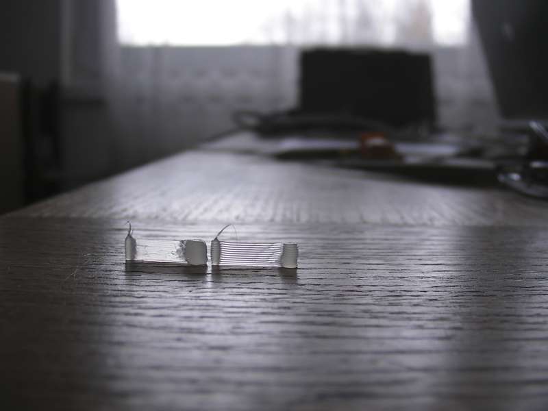
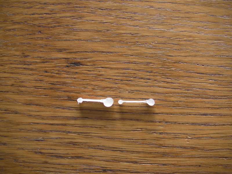
By suggest rayhicks I have done little test with printing .
Results are in attachment.
Left print have Layer height = 0.24mm and right 0.5mm (more then twice ).
Thickness 0.24 or 0.25 probably will not be great difference
Lubos
I am "greenhorn" and with interesting following this forum.
By suggest rayhicks I have done little test with printing .
Results are in attachment.
Left print have Layer height = 0.24mm and right 0.5mm (more then twice ).
Thickness 0.24 or 0.25 probably will not be great difference
Lubos
|
Re: Why 0.24mm layer thickness? February 21, 2014 09:40AM |
Registered: 10 years ago Posts: 578 |
I ran a couple of cubes with 0.24 and 0.25 spacing, and indeed there's no visible difference on quality (all layers extrude evenly in both cases) - I've attached pictures (sorry my microscope is a bit broken, and I had to backlight with a LED torch so the illumination and focus are poor, but both are clearly pretty regularly spaced):
the first is 0.25mm running at 40mm/s:
the second is 0.24 mm, same settings otherwise:
One very interesting (to me at least) thing was I upped acceleration toward the end of the 0.25mm print (from the default 800mm/s^2 to 2000), and it had a marked effect on corner quality - my camera and scope can't capture the difference, but it removed some of the overshoot apparent at the lower acceleration and gave a more well defined corner ( I also resliced at 100mm/s, and the corners degraded, presumably because they didn't have time to harden between layers - there was no apparent difference elsewhere),
All in all I'd say I was very mistaken in the views I expressed last night
Ray
the first is 0.25mm running at 40mm/s:

the second is 0.24 mm, same settings otherwise:

One very interesting (to me at least) thing was I upped acceleration toward the end of the 0.25mm print (from the default 800mm/s^2 to 2000), and it had a marked effect on corner quality - my camera and scope can't capture the difference, but it removed some of the overshoot apparent at the lower acceleration and gave a more well defined corner ( I also resliced at 100mm/s, and the corners degraded, presumably because they didn't have time to harden between layers - there was no apparent difference elsewhere),
All in all I'd say I was very mistaken in the views I expressed last night
Ray
|
Re: Why 0.24mm layer thickness? February 21, 2014 09:46AM |
Registered: 10 years ago Posts: 578 |
Quote
Mr.Lupastr
Hi,
I am "greenhorn" and with interesting following this forum.
By suggest rayhicks I have done little test with printing .
Results are in attachment.
Left print have Layer height = 0.24mm and right 0.5mm (more then twice ).
Thickness 0.24 or 0.25 probably will not be great difference
Lubos
Hi Lubos - I'm impressed that the 0.5 print looks so good - it's hard for a nozzle to extrude accurately at around the full diameter (since it can't press the layers together).
I was looking at the difference between very small changes in layer height though, to see if they made a difference to the accuracy of the layer height as the Z axis moved upwards (thinking that for some small changes the Z axis couldn't move accurately enough for a regular pattern),
Cheers
Ray
|
Re: Why 0.24mm layer thickness? February 21, 2014 10:58AM |
Registered: 10 years ago Posts: 2,472 |
Hmmm. Increasing the acceleration reduced the corner overshoot? I wonder how that works?
Regarding 0.5mm layers - I would have thought that the height & width of the plastic deposited is independent of the nozzle diameter until they become quite a lot bigger than the nozzle diameter. The height will surely be set by the distance between the nozzle and the previous layer, and the width by the speed of extrusion in relation to the speed of head movement & height? Think of a stationary nozzle sat (say) 2mm above the bed - extruding a bit of plastic will soon produce a mound that fills that 2mm gap whatever the nozzle diameter, so there should be no problem laying a 2mm high trail. It's not something that I've given a great deal of thought to though, and there are probably factors I am not considering.
Dave
(#106)
|
Re: Why 0.24mm layer thickness? February 21, 2014 12:14PM |
Registered: 10 years ago Posts: 9 |
Hi Ray,
very nice pictures. I agree with you - isn't visible any difference quality between pictures.
A bit mathematics:
Nozle diameter D=0.5mm -> radius r=0.25mm -> surface S=PI*r2 = 0.1963 mm2.
But I wont build with square profil, not with circular profil.
edge will be SQRT from 0.1963 and it is 0.44mm
That is only mathematics, reality is different.
Is necessary layers more push to put together. That's why choice 0.24 mm Layer high is OK. Layers will be better "connated"
- amount supplied masses will be calculated by Slic3r.
Ahoj
Lubos
Edited 2 time(s). Last edit at 02/22/2014 06:04AM by Mr.Lupastr.
|
Re: Why 0.24mm layer thickness? February 21, 2014 12:36PM |
Registered: 10 years ago Posts: 578 |
@dave -not sure, I guess that it's slowing down quicker then getting the hell out of there faster - give it a try (I didn't increase the speed, just the acceleration.).
on the extrusion thing, if you extrude into air, the filament comes out at nozzle diameter then (depending on flowrate and temperature) it swells a little ( I did this the other day with a fairly fast extrude of PLA at 185, 195 and 205 I got a change from around 1.0 mm at 185 °C down to around 0.6 at 205. I think however that slic3r presumes that it comes out nozzle sized and circular, then decides how fast to extrude to get a layer of the required height. If you leave a gap higher than the filament will swell to, extruding more per x/y move won't make it that much thicker, just longer and more snakey maybe.
Ray
|
Re: Why 0.24mm layer thickness? February 21, 2014 01:59PM |
Registered: 10 years ago Posts: 2,472 |
Quote
rayhicks
@dave -not sure, I guess that it's slowing down quicker then getting the hell out of there faster - give it a try (I didn't increase the speed, just the acceleration.).
on the extrusion thing, if you extrude into air, the filament comes out at nozzle diameter then (depending on flowrate and temperature) it swells a little ( I did this the other day with a fairly fast extrude of PLA at 185, 195 and 205 I got a change from around 1.0 mm at 185 °C down to around 0.6 at 205.
If extruding into air I can see that. However we are usually extruding onto a surface just below the nozzle that will catch the molten plastic and cause it to build up and push outward, eventually forming a sticky ball a great many times the nozzle diameter. The only time the plastic will not fill the gap between the nozzle and the surface we are extruding onto is if the extruder is not pumping out material fast enough to fill the gap as the head moves - and that's only going to happen if it is trying to produce a thread that is too narrow. I can see that as you increase the gap (layer thickness) you also have to increase the width, and I suspect that the width needs to be greater than the thickness to allow the head to squeeze it to the right height and flatten it out. The cross-sectional shape of the thread laid down is not circular, but is flat top & bottom.
Dave
(#106)
|
Re: Why 0.24mm layer thickness? February 21, 2014 02:18PM |
Registered: 10 years ago Posts: 578 |
yes it's flat top and bottom because it's pushed out between the two surfaces (nozzle tip and glass) that are closer than the diameter it would have if in free air - if you're (say) 2mm up using a 0.5mm nozzle, you're pretty much in free air and you'd probably lay a track of cylindrical squiggles in my mind - I guess one of us is going to have to try it
Cheers
Ray
Cheers
Ray
|
Re: Why 0.24mm layer thickness? February 22, 2014 05:14AM |
Registered: 10 years ago Posts: 9 |
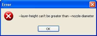
Hi,
about 3 days ago I had investigate about it.
Slicr3r is capable work only with max layer high equal nozzle diameter (see attach.)
In this case filaments with circle profile only lies. Block have interspaces and maybe - break up
Lubos
Edited 1 time(s). Last edit at 02/22/2014 06:08AM by Mr.Lupastr.
about 3 days ago I had investigate about it.
Slicr3r is capable work only with max layer high equal nozzle diameter (see attach.)
In this case filaments with circle profile only lies. Block have interspaces and maybe - break up
Lubos
Edited 1 time(s). Last edit at 02/22/2014 06:08AM by Mr.Lupastr.
Sorry, only registered users may post in this forum.