Is this a pronterface fault?
Posted by alanbattersby
|
Is this a pronterface fault? February 22, 2014 01:43PM |
Registered: 10 years ago Posts: 55 |
Hi,
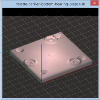
As usual object created with DesignSpark Mechanical and stl file exported. Slice3R 1.0.0 RC2 displays park correctly in its view.
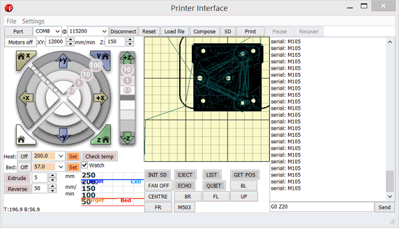
Gcode the exported using standard Ormerod settings I have used successfully until today, and loaded into pronterface (altered version) which displays outline ok ish, the part seems to be offset against the skirt. I also get this part view if I directly load the stl into pronterface.
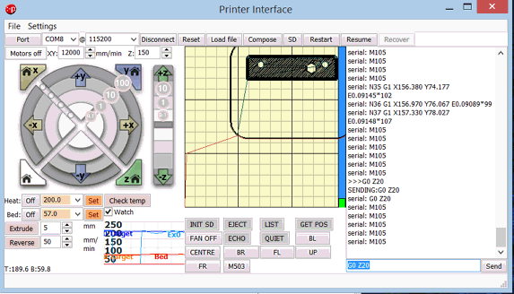
But when I press the pronterface print button the view changes to a cut-down version
And its the cut-down bit that starts to print.
Can anyone guess what is going on? Is it a bug in Slic3R or in Pronterface or a fault in my stl file or my original model?
Suggestions welcome thanks
Alan
|
Re: Is this a pronterface fault? February 22, 2014 02:46PM |
Registered: 11 years ago Posts: 103 |
|
Re: Is this a pronterface fault? February 22, 2014 05:10PM |
Registered: 10 years ago Posts: 55 |
There was no part that extended below Z=0, but it must be a problem with the stl that DesignSpark exported which could not be fixed by slic3R. I have redrawn the part slightly differently and this time there does not seem to be a problem. I have not tried printing the new part yet but at least the it lies inside the skirt. Will try an actual print tomorrow. I am running pronterface on windows 8 but there is a graphics problem examine/edit layers does not display anything and no response to clicking the arrows etc.
Alan
Alan
|
Re: Is this a pronterface fault? February 23, 2014 07:00PM |
Registered: 10 years ago Posts: 2,472 |
It is quite common when designing a part to end up with bits that are not completely flush, usually due to rounding errors within the CAD software. You may have experienced that sometimes a 10mm deep hole in a 10mm wall fails to go completely through, for example, but leaves a thin sliver of material covering the hole. Similarly, a 10mm wall laid next to another 10mm wall does not always completely line up even if it looks fine in the rendering on screen. You may have had an underhang of 0.001mm or so, which was invisible in the display but Slic3r took to be the bottom layer. Some CAD software automatically fixes those things, others do not. You can usually manually fix it by creating a large rectangle around the print 1mm below it, and use that outline to do an upwards cut (cut extrude tool) of distance 1.01mm - so long as you can live with shaving 0.01mm off your design of course.
Dave
(#106)
Dave
(#106)
Sorry, only registered users may post in this forum.


