Hacking the Alpine PSU
Posted by bobtidey
|
Hacking the Alpine PSU February 28, 2014 07:02PM |
Registered: 10 years ago Posts: 209 |
First the big caveats. Most importantly, do not attempt this if you are not confident about working with high voltage electronics. Switch mode power supplies retain significant high voltage charge on their capacitors for long periods of time (days). If you don't know how to safely discharge the electronics then you are very likely to get a shock which can be of dangerous magnitude. You will obviously invalidate any warranty. You can also achieve the same results by getting a dedicated PSU for a modest price like others have done, so this is only for those who like to work with what they have.
So what was I trying to achieve. A PSU that doesn't vary too much under load and which can feed a good voltage to the heaters so they warm up quicker and to higher temperatures. As others have pointed out the problem with the standard arrangements is that the 12V of the PSU dips quite a bit under load and there is significant drop in the cables. The fan changes noise and the voltage at the bed can get marginal if one wants to get up to ABS temperatures. Before any modification my PSU was dipping by 1.1V by the time it got to the heater. 0.4V was down to the ribbon cable but the rest was poor regulation in the PSU and drop in the relatively light weight PC harness. I also wanted to get rid of the messy PC wiring harness.
The modifications consist of two parts which are independent of each other but the maximum benefit is from the combination.
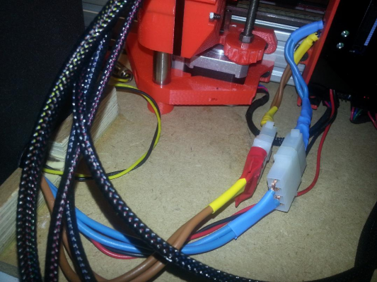
The first modification is fairly standard and I think others have done this as well. This is to replace the standard PC wiring harness with dedicated wiring. I took out all the whole harness and brought out 3 connections; a main +12V power feed direct to the Duet, a secondary +12V low power feed which I use to power a little 24 LED lamppost for local illumination, and a +5V feed which I use to power the Duet via its external J10 option. I prefer this rather than use the on-board regulator. I removed the Stdby +5V, the -12V, the Power Good signal. 3.3V is also disconnected but I wire the brown 3.3V sense wire to the +3.3V inside the supply to keep that happy. Similarly I wire the PS On signal to 0V inside the supply so the PSU turns on straight away. The wiring I used for the main +12V power was 2 big wires for each connection. I put Molex connectors in each path so the current is spread over 4 pins on each wire and I can disconnect easily without touching the Duet connectors. The leads then go straight into the Duet. The resistance of this connection is much less than the original PC harness. The existing PC distribution board is no longer used. This image shows the cabling coming out of the PSU now.
The second modification attacks the root cause of the Power supply poor regulation. The Alpine PSU like most ATX supplies generates all the main outputs from one switcher. This means they are not independently controlled. The approach the Alpine uses like a lot of other supplies is to combine the +5V and +12V in the feedback path so that regulation is a 'average' between the two outputs. This works well in a computer environment where there is significant loading on both +12V and +5V rails. Here though the load on the +5V is relatively low whilst that on the +12V is high and varies a lot as the heaters switch on and off. The net result is that the +5V doesn't dip much and the feedback therefore isn't so effective at maintaining the +12V which was changing by about 0.5V under load.
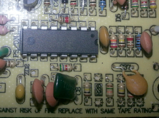
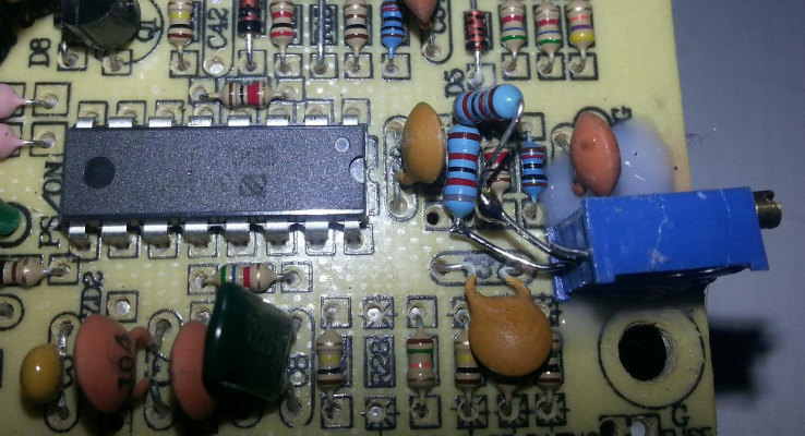
The main control chip in the Alpine is a fairly obscure part which I believe to be a Weltrend WT7520 (at least it has the same pin out and functionality). This image shows the area of the board (near the Power input).
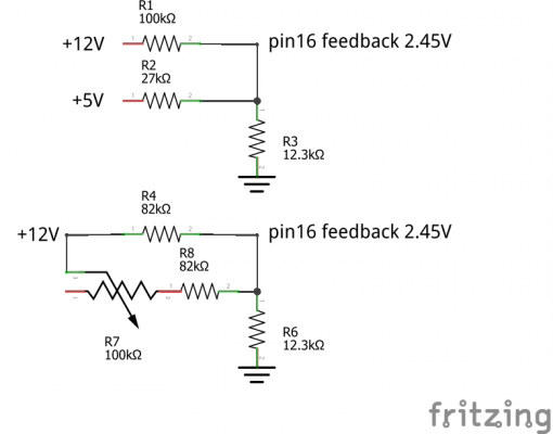
The part of interest is pin 16 of the part which is the regulation feedback input. This is like in the top part of the diagram (before modification). The pin is being compared to an internal 2.45V reference voltage. The potential divider consists of a number of resistors in parallel to ground equivalent to a 12.3K resistor so 0.2mA should flow to ground normally. The hot side of the divider is fed by both the +5V supply through a 27K resistor and the +12V supply through a 100K resistor. So the contribution to the feedback is equally split between the two supplies. The two resistors in question are to the right of the IC in the image and just the other side of the capacitor.
The modification is show in the bottom half of the schematic. I removed the 27K resistor and +5V feedback and replaced the +12V 100K resistor so that all the feedback comes from that path. This would require nominally a 48K resistor. Instead I use a network of 2 82K resistors and a 100K trimpot. This allows adjustment of the output voltage from about 10.5V up to about +13.8V although the overvoltage protection circuits built into the chip might kick in a little lower than that.
Physically it means removing the 2 resistors next to the chip they can be seen in the premod image. One 82K resistor goes in place of the 100K and the trim pot goes to one side of this and another 82k connects the other trim pot connection to the other side. I just mounted the trim pot on the board and drilled a little hole in the case to give external access to the screw.
The +5V output is no longer part of any feedback so it just scales with any adjustment to the +12V output affects it. So 11V out -> 4.6V , 12V -> 5.12, 12.5V -> 5.34, 13V -> 5.55, and 13.5V ->5.76V. This should not be of much concern if it is used as the Duet logic supply as the +5V is regulated down to 3.3V before it is used.
The +12V regulation is now pretty good and combined with the wiring change means I see about 0.1V change as measured at the Duet input between heaters on and off, and no fan noise changes. By setting the output to +12.4V I get +12V at the bed terminals.
The other consideration is that by removing the PC harness connector the load resistors which draw a basic current are no longer in the circuit. I haven't tried checking whether the PSU minds that much as the +5V is getting the logic load and in my case my LED illumination tower draws the same amount of current from the +12V as the previous resistor did, and it does something more useful than generate heat.
|
Re: Hacking the Alpine PSU February 28, 2014 07:32PM |
Registered: 10 years ago Posts: 578 |
|
Re: Hacking the Alpine PSU February 28, 2014 08:11PM |
Registered: 10 years ago Posts: 209 |
|
Re: Hacking the Alpine PSU February 28, 2014 08:27PM |
Registered: 10 years ago Posts: 578 |
 Joking aside, could you post before and after shots in the same orientations of the areas you modded just for the older-eyed and more easily confused among please?
 ]
]Cheers
Ray
Edited 1 time(s). Last edit at 02/28/2014 08:32PM by rayhicks.
|
Re: Hacking the Alpine PSU March 01, 2014 05:13AM |
Registered: 10 years ago Posts: 209 |
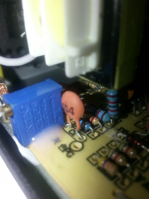
OK. Here is an after mod image from a similar angle as the previous before image.
The 27K resistor is gone. An 82K resistor is in place of the 100K. The trimpot is glued in place with one leg bent and soldered to one end of the 82K. The middle leg of the trimpot then goes to one end of another 82K resistor and the other end of that is soldered to the end of the 82K in place on the board. I didn't need to use any wiring, just soldering the leads together. It is important to keep the trimpot fairly well pushed onto the board otherwise its screw will clash against the edge of the case.
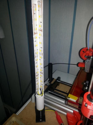
This is the LED lampost I use. Just 2 x 12 LED strips glued into a half-pipe on a rotating base. Draws about 400mA but gives a nice bright light. Doesn't effect the IR sensor too much.
|
Re: Hacking the Alpine PSU March 01, 2014 05:16AM |
Registered: 10 years ago Posts: 300 |
Hi bobtidy, I've all but given up on trying to engineer a "safe" external mod people could do to their supplies - so "solutions for the experienced hacker only" seem to be the last resort (short of laying out a modest amount of money for a more suitable PSU). You mentioned that you connected the 3.3V sense wire direct to the 3.3V O/P inside the supply - without any dummy load. This implies that the independent 3.3V regulation circuit is happy without any load at all. I had already figured that it was entirely independent by loading the rails one at a time and found the 5V & 12V pulled each other around but not the 3.3V.
Did you try a no-load test after you did the modification? I only ask because we keep seeing minimum loading specs. for these supplies. In the case of the 5V/12V circuits the hot-end fan and motors at idle keep the current flowing - until dc42 has the fan shut off when cold and the "motors off" command is issued. I Think the Duet board can be counted on drawing at least 0.5A from the 5V supply which may keep things withing the minimum spec. except, of course, if the ATX 5V output isn't used and the USB lead is plugged in.
RS Components Reprap Ormerod No. 481
|
Re: Hacking the Alpine PSU March 01, 2014 06:00AM |
Registered: 10 years ago Posts: 256 |
Genius! 
Might have a go at this if I want to print ABS!
Dont see a reason to use an external 5v supply though? Would just use 12V which wouldnt require any mods to your circuit AFAICS?.
Also would be worth adding an inline fuse. You can now easily compensate for any voltage drop !
Thanks!
regards
Andy
Ormerod #318
www.zoomworks.org - Free and Open Source Stuff

|
Re: Hacking the Alpine PSU March 01, 2014 06:30AM |
Registered: 10 years ago Posts: 14,672 |
If you don’t use the 5V output to power the Duet 5V then you will probably need to put a dummy load on the 5V output.
Large delta printer [miscsolutions.wordpress.com], E3D tool changer, Robotdigg SCARA printer, Crane Quad and Ormerod
Disclosure: I design Duet electronics and work on RepRapFirmware, [duet3d.com].
Large delta printer [miscsolutions.wordpress.com], E3D tool changer, Robotdigg SCARA printer, Crane Quad and Ormerod
Disclosure: I design Duet electronics and work on RepRapFirmware, [duet3d.com].
|
Re: Hacking the Alpine PSU March 01, 2014 07:21AM |
Registered: 10 years ago Posts: 578 |
|
Re: Hacking the Alpine PSU March 01, 2014 07:31AM |
Registered: 10 years ago Posts: 209 |
I'll try to run some dummy load tests later and report back.
The Alpine 5V supply is likely to override the USB supply with the diode arrangements so the current will come from the PSU rather than USB if J10 powering is used. If J9 powering is used then it will definitely come from the PSU via the +12V as there is no diode in that path.
I'd speculate that the 5V load isn't that important if a decent amount of current is being drawn from the +12V and no use is made of the +5V output (e.g. J9 internal Duet powering). This is because the +5V is no longer contributing to the feedback. Where it might have some effect is that it might 'float' high under very light loading. During testing before I connected to Duet I was using a 200mA load on the +5V and the output was fine then. What I'll try is reducing the loads on both +12V and +5V to see what the effect is.
Not sure about the effect on noise. The +5V from the PSU seems fairly quiet and I don't see any ill effects from moise. I've never used the on-board regulator as originally I had one of the faulty Duets where this didn't work so I started using the J10 scheme and continued with that after the board was replaced. The main advantage of the on-board is if you want a single +12V source. If there is +5V around then it made sense to me to use it.
Edited 1 time(s). Last edit at 03/01/2014 07:34AM by bobtidey.
|
Re: Hacking the Alpine PSU March 01, 2014 08:16AM |
Registered: 10 years ago Posts: 14,672 |
The 5V switching regulator on the board causes quite a lot of noise to appear on the Z probe reading. See [forums.reprap.org] and also 2 posts later in the same thread.
Large delta printer [miscsolutions.wordpress.com], E3D tool changer, Robotdigg SCARA printer, Crane Quad and Ormerod
Disclosure: I design Duet electronics and work on RepRapFirmware, [duet3d.com].
Large delta printer [miscsolutions.wordpress.com], E3D tool changer, Robotdigg SCARA printer, Crane Quad and Ormerod
Disclosure: I design Duet electronics and work on RepRapFirmware, [duet3d.com].
|
Re: Hacking the Alpine PSU March 01, 2014 11:32AM |
Registered: 10 years ago Posts: 209 |
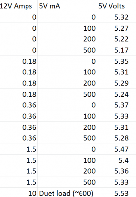
Here are some load tests. I didn't bother too much with 3.3V loading. I checked it was 3.3V due to the local sense. The previous scheme and the modded one makes no load or usage of the 3.3V supply. The 12V supply was set to 12.4V and didn't vary by more than 0.05V for any of the tests so I haven't bothered to report that.
The regulation seems to work pretty well under no load on the 12V and 5V supplies.
At any particular 12V load the 5V supply decreases a bit as its load increases as it is no longer in the feedback loop but it's still pretty stable.
As the 12V load increases the base point for the +5V goes up. I think this is because the +12V is working harder to maintain the O/P and the +5V goes up a bit as a consequence.
I only have 1 measurement at the highest current as that is a real world measurement. The increase in +5V seems to have levelled off a bit by then. It's getting a bit high for powering logic that really expects 5V (max 5.25) but this isn't the case for the Duet. In there it is also going through a diode before doing anything so that brings it down in range.
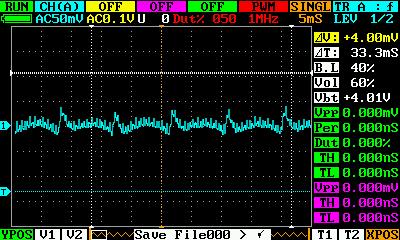
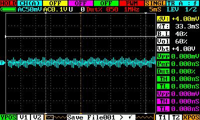
I haven't noticed any noise problems and the unmodded IR probe is pretty stable. I did a few checks with a scope on the PSU as the measurements were all just DC meter. The +5V was very quiet, less than 10mV. The +12V was a bit noisier with a little bit of a low frequency mains component under no load, but still pretty quiet.
Loading the +12V removed the low frequency component.
|
Re: Hacking the Alpine PSU March 01, 2014 01:27PM |
Registered: 10 years ago Posts: 578 |
|
Re: Hacking the Alpine PSU March 02, 2014 05:11AM |
Registered: 10 years ago Posts: 300 |
Quote
bobtidey
Here are some load tests. I didn't bother too much with 3.3V loading. I checked it was 3.3V due to the local sense. The previous scheme and the modded one makes no load or usage of the 3.3V supply.
Sure, nothing actually makes use of the 3.3V rail from the ATX PSU but switch-mode power supplies in general have several protection schemes and one of them is sensing minimum load and shutting down if the load is below specification. In most cases this is to guarantee that voltage regulation is maintained - i.e. some output stages can become unstable without sufficient loading. The Ormorod kit came with a junction box containing dummy load resistors for the 3V and 5V rails for this reason. With your mods, your PSU would now appear to be operating without a dummy load on the 3.3V rail - I was just curious to know if this was OK.
RS Components Reprap Ormerod No. 481
|
Re: Hacking the Alpine PSU March 02, 2014 05:57AM |
Registered: 10 years ago Posts: 256 |
Quote
Radian
Quote
bobtidey
Here are some load tests. I didn't bother too much with 3.3V loading. I checked it was 3.3V due to the local sense. The previous scheme and the modded one makes no load or usage of the 3.3V supply.
Sure, nothing actually makes use of the 3.3V rail from the ATX PSU but switch-mode power supplies in general have several protection schemes and one of them is sensing minimum load and shutting down if the load is below specification. In most cases this is to guarantee that voltage regulation is maintained - i.e. some output stages can become unstable without sufficient loading. The Ormorod kit came with a junction box containing dummy load resistors for the 3V and 5V rails for this reason. With your mods, your PSU would now appear to be operating without a dummy load on the 3.3V rail - I was just curious to know if this was OK.
AFAICS The Undervoltage and overvoltage is all handled in this IC WT7520.pdf]
The only other question is whether the circuitry in the Alpine PSU uses its own outputs to supply its logic cicuits in which case you cant pull the supplies too far from there intended voltages AFAICS.
Anyway its a brilliant mod!
regards
Andy
Ormerod #318
www.zoomworks.org - Free and Open Source Stuff

|
Re: Hacking the Alpine PSU March 02, 2014 06:55AM |
Registered: 10 years ago Posts: 209 |
The internals typically use the standby 5V as that is derived separately from the main switcher. It allows the control chip to be in a sensible state, sense power on with the switcher off, and run the monitoring of the outputs no matter what state they are in. That seems to be the case here.
The control chips do not normally sense load current directly instead they have under-voltage and over-voltage detectors on at 3.3,5,12 and aux which is a catch all for the other rails.
3.3V rail has to be between 2 and 4V to be OK. Mine was 3.3 without any extra load. As you say the power distribution board does actually have a 22R load on the 3.3 rail and a 30R on the +5 , but nothing on the +12V which is a little puzzling given that it is a primary output and part of the feedback. Maybe the fan was thought to be sufficient. One could easily put equivalents inside the supply on the +5V and +3.3 rails if one wanted to, particularly with all the old wiring removed there is plenty of space in that area.
|
Re: Hacking the Alpine PSU March 02, 2014 09:23AM |
Registered: 10 years ago Posts: 300 |
I'm sure it's all good. I just wondered if the 3.3V control circuit was part of the WT7520 or if it was independent - as I'd suspected from my own external load tests. Looking at a number of different schematics, I got the impression the 3.3V was considered more critical hence had it's own closed-loop regulation circuity. In the past I've used cheap ATX supplies without any concern over minimum loading - just ground the green wire and go.
RS Components Reprap Ormerod No. 481
RS Components Reprap Ormerod No. 481
|
Re: Hacking the Alpine PSU March 02, 2014 04:57PM |
Registered: 10 years ago Posts: 209 |
The 3.3V does have its own independent regulator. It looks like it is derived down from the +5V but I can't be certain as I don't have an overall schematic for this particular design. However, I am certain it is not part of the overall main feedback loop. The only bit of the WT7520 looking at the 3.3V is the pin responsible for checking its under/over voltage condition.
I think this arrangement is fairly typically. I believe the 3.3V got this special treatment when 3.3 was the main source for the CPU so the voltage was quite critical and there was also concern over drop in the cables for a low voltage source. That is not the case in modern motherboard practice where it is the +12V supply that supplies the bulk power to a local on-board regulator giving an even lower and adjustable source of volts to the processor.
I think this arrangement is fairly typically. I believe the 3.3V got this special treatment when 3.3 was the main source for the CPU so the voltage was quite critical and there was also concern over drop in the cables for a low voltage source. That is not the case in modern motherboard practice where it is the +12V supply that supplies the bulk power to a local on-board regulator giving an even lower and adjustable source of volts to the processor.
|
Re: Hacking the Alpine PSU March 03, 2014 05:01AM |
Registered: 10 years ago Posts: 300 |
So (in the absence of a true current sense) I get how under-voltage might be used as a proxy for current overload, but I wonder what conditions might cause over-voltage? Obviously failure of some other part of the PSU could be caught - but if it can maintain regulation (keeping under the maximum trip points) with zero load current then dummy loads seem pointless. Your tests show that there's no problem maintaining 3.3V under no load. I'm all for saving our skins from climate change through avoiding unnecessary power consumption!
RS Components Reprap Ormerod No. 481
RS Components Reprap Ormerod No. 481
|
Re: Hacking the Alpine PSU March 03, 2014 06:04AM |
Registered: 10 years ago Posts: 209 |
Some ATX PSU's do contain genuine over-current sensing and protection circuits. This is supposed to meet a IEC requirement that no single wire should supply more than 240VA (20A on 12V). Some supplies actually split their +12V into dual rails each with 20A circuits but that was also a pain in deciding what circuits got which rails. Low end supplies like the Alpine are normally single rail and ignore the direct overcurrent protection. They sort of comply with the IEC requirement by having multiple wires.
The overvoltage protection was part of the original ATX12V spec to guard against single faults in the PSU endangering the motherboard. The minimum load requirement will vary from design to design. The Alpine seems comfortable with no extra external load but other switchers definitely need a minimum load to work properly.
The overvoltage protection was part of the original ATX12V spec to guard against single faults in the PSU endangering the motherboard. The minimum load requirement will vary from design to design. The Alpine seems comfortable with no extra external load but other switchers definitely need a minimum load to work properly.
|
Re: Hacking the Alpine PSU April 17, 2020 09:47AM |
Registered: 4 years ago Posts: 4 |
Sorry, only registered users may post in this forum.
