Capacitive Z-height sensing
Posted by Radian
|
Capacitive Z-height sensing March 11, 2014 09:09AM |
Registered: 10 years ago Posts: 300 |
In the continued quest to develop a better Z-height sensor I finally got around to testing a capacitive sensing probe. The principle is simple enough - create an oscillator that varies it's frequency with changes in capacitance in part of its circuit. By using the alluminium heat spreader as one plate of the capacitor and a square of tea-caddy tin under the X-carriage as the other, I'm generating a height dependent frequency using the onboard Capacitive Sensing Module in a PIC12F1822
The shiny tin part is soldered directly to the stripboard carrying the PIC. This board bolts on in place of original IR sensor board so the tin "foot" ends up sitting parallel to the bed, roughly at the same height as the tip of the nozzle. I also tried connecting the capacitive sensor input directly to the metal hot-end assembly but the frequency change wasn't anywhere near as pronounced. This is understandable when you look at the small surface area of the nozzle which is the only part that gets close to the bed. The purpose-made plate has a far greater area.
Initial tests look promising. So far I'm just reading back raw counter values from a gated timer using the CSM as clock source. To get a feel for the readings the counts are currently typically like this:
There's dancing in the lowest two digits, but the oscillator timebase in the PIC is only internal CR so I'm expecting better results using an crystal. The next step is to convert the counts into a PWM derived analogue signal that can be fed into the Duet as Z-height.
Unlike Ultrasound, the readings appear to be largely unaffected by temperature and of course ambient light! I expect Electrical noise will prove to be the main environmental hazard - although so far it seems pretty clean. As for humidity, further testing is needed to find out if this is an issue or not. Previous experience with this kind of sensing tells me that Long-term drift is going to need addressing.
RS Components Reprap Ormerod No. 481


The shiny tin part is soldered directly to the stripboard carrying the PIC. This board bolts on in place of original IR sensor board so the tin "foot" ends up sitting parallel to the bed, roughly at the same height as the tip of the nozzle. I also tried connecting the capacitive sensor input directly to the metal hot-end assembly but the frequency change wasn't anywhere near as pronounced. This is understandable when you look at the small surface area of the nozzle which is the only part that gets close to the bed. The purpose-made plate has a far greater area.
Initial tests look promising. So far I'm just reading back raw counter values from a gated timer using the CSM as clock source. To get a feel for the readings the counts are currently typically like this:
Z Counter
0.0 13500
0.1 13620
0.2 13750
0.3 13930
0.4 14200
0.5 14500
0.6 14750
0.7 14960
0.8 15190
0.9 15250
1.0 15400

1.5 15800
2.0 16100
3.0 16500
5.0 16900
10 17100
There's dancing in the lowest two digits, but the oscillator timebase in the PIC is only internal CR so I'm expecting better results using an crystal. The next step is to convert the counts into a PWM derived analogue signal that can be fed into the Duet as Z-height.
Unlike Ultrasound, the readings appear to be largely unaffected by temperature and of course ambient light! I expect Electrical noise will prove to be the main environmental hazard - although so far it seems pretty clean. As for humidity, further testing is needed to find out if this is an issue or not. Previous experience with this kind of sensing tells me that Long-term drift is going to need addressing.
RS Components Reprap Ormerod No. 481
|
Re: Capacitive Z-height sensing March 11, 2014 09:44AM |
Registered: 10 years ago Posts: 14,672 |
Interesting! What is the size of the foot, and have you calculated the capacitance? My feeling was that the capacitance achievable would be too low to make this reliable, but perhaps I was wrong.
If you used glass coated with tin oxide on the top surface as in [www.youtube.com], you could use it as the lower plate and get greater capacitance.
Edited 1 time(s). Last edit at 03/11/2014 09:45AM by dc42.
Large delta printer [miscsolutions.wordpress.com], E3D tool changer, Robotdigg SCARA printer, Crane Quad and Ormerod
Disclosure: I design Duet electronics and work on RepRapFirmware, [duet3d.com].
|
Re: Capacitive Z-height sensing March 11, 2014 10:15AM |
Registered: 10 years ago Posts: 300 |
Hi dc42,
Input: A = 20mm x 20mm square of tin, D = 3mm above glass (K=5 ?)
C=K*Eo*A/D,
=5*8.854x10-12*0.0004/0.003
=6pF
Not much on paper, agreed, but all in a day's work for a half-decent CSM like the one in the PIC
I'm very keen on getting it to work reliably with the stock glass, but yes, coated glass would totally transform the situation. Mind you, in that case we could just dangle a wire contact to the surface!
RS Components Reprap Ormerod No. 481
|
Re: Capacitive Z-height sensing March 11, 2014 11:31AM |
Registered: 10 years ago Posts: 14,672 |
Actually, if the dielectric constant of glass is as high as 5 (and I've just found 7.75 quoted here [www.valleydesign.com]), then coated glass won't make much difference, assuming the sensor is about 1mm or more above the surface of the glass at the measurement position.
Large delta printer [miscsolutions.wordpress.com], E3D tool changer, Robotdigg SCARA printer, Crane Quad and Ormerod
Disclosure: I design Duet electronics and work on RepRapFirmware, [duet3d.com].
Large delta printer [miscsolutions.wordpress.com], E3D tool changer, Robotdigg SCARA printer, Crane Quad and Ormerod
Disclosure: I design Duet electronics and work on RepRapFirmware, [duet3d.com].
|
Re: Capacitive Z-height sensing March 11, 2014 11:31AM |
Registered: 10 years ago Posts: 256 |
Excellent! Glad this looks promising. Someone also suggested using two plates side by side on the hot end. You 1/4 the capacitance but dont need a connection to the heater plate.
regards
Andy
Ormerod #318
www.zoomworks.org - Free and Open Source Stuff
Someone also suggested using two plates side by side on the hot end. You 1/4 the capacitance but dont need a connection to the heater plate.regards
Andy
Ormerod #318
www.zoomworks.org - Free and Open Source Stuff
|
Re: Capacitive Z-height sensing March 11, 2014 11:35AM |
Registered: 10 years ago Posts: 14,672 |
Quote
kwikius
Excellent! Glad this looks promising.
I suggested that, but I was still intending that the heater plate be used as one side of the capacitor. One side of the bed thermistor is already connected to 0V, so I would just connect a resistor between this connection and the plate (a resistor rather than a wire, to give some protection for the Duet against short circuits to the heated bed connections).
Large delta printer [miscsolutions.wordpress.com], E3D tool changer, Robotdigg SCARA printer, Crane Quad and Ormerod
Disclosure: I design Duet electronics and work on RepRapFirmware, [duet3d.com].
|
Re: Capacitive Z-height sensing March 11, 2014 12:39PM |
Registered: 10 years ago Posts: 300 |
Unless I'm misunderstanding you, the heat spreader has such a large area it's pretty much already at ground. No chance of using it as the waggling end. In fact, I see no change in frequency if I croc. clip it to 0V. That's why I waggle the postage-stamp sized foot above it.
RS Components Reprap Ormerod No. 481
RS Components Reprap Ormerod No. 481
|
Re: Capacitive Z-height sensing March 11, 2014 01:37PM |
Registered: 10 years ago Posts: 256 |
My plan was to pass a sine wave of constant frequency and amplitude, amplify the result and rectify it. to give a signal inversely proportional to distance I believe there are various microcontrollers around that have all the required peripherals DAC, OpAmp, A2D and capacitive sensor too! Avoiding using the heat spreader as ground should eliminate it as a source of noise. ( I have a hunch that splitting the capacitance means any spikes cancel.. but not looked at it in detail) But I havent really done much about it its true!
regards
Andy
Ormerod #318
www.zoomworks.org - Free and Open Source Stuff
regards
Andy
Ormerod #318
www.zoomworks.org - Free and Open Source Stuff
|
Re: Capacitive Z-height sensing March 11, 2014 02:06PM |
Registered: 10 years ago Posts: 300 |
kwikius, your plan makes use of a capacitive divider then. The Capacitive Sensing Module I'm using in the PIC chip uses a cute scheme where an internal constant current sink and source alternately charges and discharges the sensor plate generating a triangle wave that varies in frequency with the amount of charge taken by the plate.
In this case the aluminium heat spreader makes a great ground to drain the charge off the plate. If noise was a worry it could readily be grounded but I'm getting repeatable results with the bed floating. It's actually something like 1nF to ground so the series effect on the gap is utterly swamped. I'm in two minds about grounding the metalwork so I think I'll stay on the fence awhile longer.
RS Components Reprap Ormerod No. 481
|
Re: Capacitive Z-height sensing March 11, 2014 02:15PM |
Registered: 10 years ago Posts: 101 |
Great work @Radian,
I have had a ton of Z-calibration problems and have been thinking about an even amount of different ways to get an easy and reliable Z-calibration - but capacitive sensing hasn't come across my mind.
A couple of years ago I tested a capacitive touch chip and got pretty good results. Only 6 pins and a couple of external components, and you have an digital output.
Basically we do not need to measure the Z-height - a digital "switch" will be fine.
I'll check up on it when I go to work tomorrow and see if I can find some of my test-PCBs and schematic.
Best regards,
Carsten
|
Re: Capacitive Z-height sensing March 11, 2014 02:40PM |
Registered: 10 years ago Posts: 300 |
colsenfoto - thanks for your encouragment 
OK, so I've got filtered PWM giving a 0 to 3.3V Z-probe height form the CSM counter. To get sensible scaling I'm tracking the minimum/maximum counts found while moving Z and scaling the value sent to the 10-bit PWM generator accordingly. So here's the numbers from the web interface:
The readings dither more the higher the probe - within the first mm or two it looks most usable but there's a spread of values of around 10 to 20 which equates to less than 0.1mm
Sounds good, but I'm not happy with the way it seems to "lurch" - several readings in a row can be within a few counts then it drops by 10 and stays around there for a while... then... you get the drift. Still using the PIC RC timebase which is embarrassing but I think it's supposed to be good for 1% or so.
Where I see a problem is that the auto-scaling gets thrown right out if you touch the sensor. Without it, the sensitivity goes down considerably. The raw counter values have been ranging from 13000 to 17000 (out of 65535) so, while the upper value doesn't go much further (probe well isolated) the lower can fall all the way to zero if shorted or touched.
RS Components Reprap Ormerod No. 481
OK, so I've got filtered PWM giving a 0 to 3.3V Z-probe height form the CSM counter. To get sensible scaling I'm tracking the minimum/maximum counts found while moving Z and scaling the value sent to the 10-bit PWM generator accordingly. So here's the numbers from the web interface:
Z Zprobe
0.0 1010
0.1 990
0.2 908
0.3 844
0.4 760
0.5 701
0.6 667
0.7 626
0.8 597
0.9 558
1.0 542

1.5 420
2.0 340
3.0 260
4.0 228
5.0 178
10 100
The readings dither more the higher the probe - within the first mm or two it looks most usable but there's a spread of values of around 10 to 20 which equates to less than 0.1mm
Sounds good, but I'm not happy with the way it seems to "lurch" - several readings in a row can be within a few counts then it drops by 10 and stays around there for a while... then... you get the drift. Still using the PIC RC timebase which is embarrassing but I think it's supposed to be good for 1% or so.
Where I see a problem is that the auto-scaling gets thrown right out if you touch the sensor. Without it, the sensitivity goes down considerably. The raw counter values have been ranging from 13000 to 17000 (out of 65535) so, while the upper value doesn't go much further (probe well isolated) the lower can fall all the way to zero if shorted or touched.
RS Components Reprap Ormerod No. 481
|
Re: Capacitive Z-height sensing March 11, 2014 06:01PM |
Registered: 10 years ago Posts: 300 |
Well, this isn't helping:
Dumping the values I was putting into the PWM generator I could see they were much less noisy than the Zprobe readings after being A/D converted by the Duet. So I hooked up a couple of 1.5V batteries in series with a 100R (100uF/10nF in parallel with output) to the input of the A/D and measured 200 seconds worth of readings. This will come as no surprise to dc42 who went to the trouble of fixing a new header to get a better 0V connection for the Z-probe board. I had no idea it was this bad though.
dc42: is there a possibility of accepting a serial data input into a spare UART anywhere on the ATSAM3X8E? We're throwing away Zprobe repeatability mainly because of an awkward grounding arrangement. Standard 115200 or 57600 baud 8bit data received as a five char. ASCII string e.g. #nnnn every 16 or 32 ms for example.
RS Components Reprap Ormerod No. 481
|
Re: Capacitive Z-height sensing March 11, 2014 08:33PM |
Registered: 10 years ago Posts: 2,472 |
One thing I could think might affect the readings is the presence of people or other objects around the printer - did anything nearby move when you saw the reading jump? The other thing is whether the readings are the same for a given height at all places over the bed - if not it might require a different parameter to be set for each probe position.
Dave
(#106)
Dave
(#106)
|
Re: Capacitive Z-height sensing March 11, 2014 08:36PM |
Registered: 10 years ago Posts: 14,672 |
It should be entirely possible to use one of the UARTs in the SAM3X. Rather than sending 5 characters, I suggest encoding up to 14 bytes of data in 2 characters, with bit 7 set on the first byte and clear on the second. I was already thinking of using async protocol to send data the other way, e.g. to adjust the frequency of my sensor board for different ultrasonic transducers.
Large delta printer [miscsolutions.wordpress.com], E3D tool changer, Robotdigg SCARA printer, Crane Quad and Ormerod
Disclosure: I design Duet electronics and work on RepRapFirmware, [duet3d.com].
Large delta printer [miscsolutions.wordpress.com], E3D tool changer, Robotdigg SCARA printer, Crane Quad and Ormerod
Disclosure: I design Duet electronics and work on RepRapFirmware, [duet3d.com].
|
Re: Capacitive Z-height sensing March 12, 2014 03:36AM |
Registered: 10 years ago Posts: 101 |
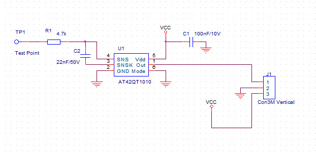
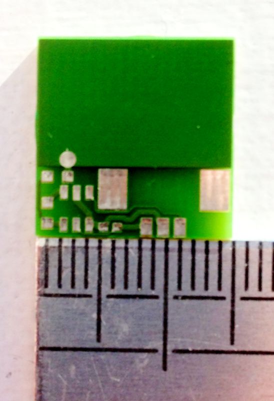
I went through my old stuff and found the capacitive sensor schematic and PCB. It's an AT42QT1010 chip - around $1 from the usual suppliers. It might be a bit difficult or expensive for private persons to find, but there are some available at ebay.
I will see, if I can find the time to test it soon. If anybody want to experiment with this one, I will be glad to help.
I agree with the comments about the grounding of the z-sensor - it is horrible. The analog signal should probably be run in a shielded cable also.
Regarding serial communication from the PIC to the duet-board. Be aware that serial communication is prone to communication errors. I have always ended up using some sort of error detection in my serial designs - at least check-sum.
Does anybody know where to find the schematic (and PCB layout) for the Z-sensor?
Best regards,
Carsten
|
Re: Capacitive Z-height sensing March 12, 2014 04:51AM |
Registered: 10 years ago Posts: 314 |
Hi, I used capacitive sensors awhile back from Q-prox, these were amazing devices/chips and were used for liquid level detection in small containers in a lab, probably a few mL. It appears Qprox is now part of Atmel (lost link!), but the original site had great design application notes and covered the issues experienced.
The guard ring was essential for small sensors as was stable materials as the probes became smaller.
Also remember the classic humidity sensor is a capacitor!
Ormerod #007 (shaken but not stirred!)
The guard ring was essential for small sensors as was stable materials as the probes became smaller.
Also remember the classic humidity sensor is a capacitor!
Ormerod #007 (shaken but not stirred!)
|
Re: Capacitive Z-height sensing March 12, 2014 05:43AM |
Registered: 10 years ago Posts: 14,672 |
I've given this some more thought, and I'm going to hack one of my sensor boards to try capacitive sensing. It should be possible by omitting some of the components for the ultrasonic sensor and changing some others. I'll use Atmel's capacitive transfer technique. The main issues look to be mechanical, i.e. how to mount the foot. One possibility is to make the printed insulator that I mount behind the board deeper, and put aluminium tape on the bottom of it.
Large delta printer [miscsolutions.wordpress.com], E3D tool changer, Robotdigg SCARA printer, Crane Quad and Ormerod
Disclosure: I design Duet electronics and work on RepRapFirmware, [duet3d.com].
Large delta printer [miscsolutions.wordpress.com], E3D tool changer, Robotdigg SCARA printer, Crane Quad and Ormerod
Disclosure: I design Duet electronics and work on RepRapFirmware, [duet3d.com].
|
Re: Capacitive Z-height sensing March 12, 2014 05:49AM |
Registered: 10 years ago Posts: 300 |
Quote
dmould
One thing I could think might affect the readings is the presence of people or other objects around the printer - did anything nearby move when you saw the reading jump? The other thing is whether the readings are the same for a given height at all places over the bed - if not it might require a different parameter to be set for each probe position.
Hi Dave, fortunately the capacitive coupling effects from items outside the bed area are negligible thanks both to the relative permeability (K) of air being 4 to 8 times greater than glass and then all divided by distance (D) (where C=K*Eo*A/D)
But I have now grounded the heat spreader because despite being itself a few thousand pF to ground (due to its large area), the coupling into it could be even greater under some conditions. With it grounded, any coupling from the periphery is shunted away from coupling to the sensor foot.
dc42 - So basically then, MIDI format
Funny you should suggest that - I always seem to get it in the neck for doing the top-bit-set control/top-bit-clear data by customers who'd rather see something more stylish - but you can't beat simple and concise! I suppose receipt of a two-byte Async. packet could be enough in itself to flag to the firmware that Z readings are available through that route?colsenfoto - the analogue signal is mostly suffering on the Duet board where it passes by the 5V switching regulator (unshielded magnetics, dubious grounding etc.) It's also referenced to the digital ground whereas the A/D convertor has a HF decoupled ground (used by all the other analogue inputs). A digital communication would be a welcome relief from all this!
Treth - As you point out, humidity may well be a significant variable although I've had working touch panels that were mounted on bikes and rain wasn't a problem. What difference it will make to the fine-grain readings remains to be seen.
RS Components Reprap Ormerod No. 481
|
Re: Capacitive Z-height sensing March 12, 2014 06:00AM |
Registered: 10 years ago Posts: 300 |
Quote
dc42
I've given this some more thought, and I'm going to hack one of my sensor boards to try capacitive sensing. It should be possible by omitting some of the components for the ultrasonic sensor and changing some others. I'll use Atmel's capacitive transfer technique. The main issues look to be mechanical, i.e. how to mount the foot. One possibility is to make the printed insulator that I mount behind the board deeper, and put aluminium tape on the bottom of it.
Excellent - I love aly tape but it's always a challenge to make a good contact to it. I keep (too many) old biscuit tins for their wafer thin, highly solderable properties. Some thin double-sided sticky tape is all it takes to mount it. It's self-supporting too.
RS Components Reprap Ormerod No. 481
|
Re: Capacitive Z-height sensing March 12, 2014 08:34AM |
Registered: 10 years ago Posts: 2,472 |
Quote
dc42
I've given this some more thought, and I'm going to hack one of my sensor boards to try capacitive sensing. It should be possible by omitting some of the components for the ultrasonic sensor and changing some others. I'll use Atmel's capacitive transfer technique. The main issues look to be mechanical, i.e. how to mount the foot. One possibility is to make the printed insulator that I mount behind the board deeper, and put aluminium tape on the bottom of it.
How about copper tape along the bottom of the fan mount? The only other issue is that it will conflict with the modification of putting the aluminium plate under the bed heater instead of on top.
Dave
(#106)
|
Re: Capacitive Z-height sensing March 12, 2014 08:36AM |
Registered: 10 years ago Posts: 578 |
|
Re: Capacitive Z-height sensing March 12, 2014 09:00AM |
Registered: 10 years ago Posts: 2,472 |
Quote
colsenfoto
Regarding serial communication from the PIC to the duet-board. Be aware that serial communication is prone to communication errors. I have always ended up using some sort of error detection in my serial designs - at least check-sum.
Not in my experience. For debugging boards I regularly use a logic-level (5V or 3.3V) standard asynchronous serial link over two meters or so of normal unshielded wire (115kBd - 1 start, 1 stop, 8 data, no parity) and have never experienced any errors whatsoever. If you get errors it is likely to be either that the signal levels are incompatible (e.g. driving 5V logic from 3.3V), you have a huge amount of noise (e.g. ground loops or bad connections), or the errors are software related (e.g. buffer over-runs). I use checksums for critical data such as firmware uploads, but a very occasional corrupted height reading is not going to do any harm.
Dave
(#106)
|
Re: Capacitive Z-height sensing March 12, 2014 09:15AM |
Registered: 10 years ago Posts: 209 |
Quote
dmould
[ The only other issue is that it will conflict with the modification of putting the aluminium plate under the bed heater instead of on top.
Dave
(#106)
Having done the mod where the spreader is below I was interested in that point as well. I wonder whether the PCB tracks would do the same job anyway as they should be effectively a ground plane for AC.
|
Re: Capacitive Z-height sensing March 12, 2014 09:40AM |
Registered: 10 years ago Posts: 300 |
Quote
bobtidey
Quote
dmould
[ The only other issue is that it will conflict with the modification of putting the aluminium plate under the bed heater instead of on top.
Dave
(#106)
Having done the mod where the spreader is below I was interested in that point as well. I wonder whether the PCB tracks would do the same job anyway as they should be effectively a ground plane for AC.
True, the heater tracks are AC coupled to ground, but the effective surface area is considerably lessened. Still, worst case, a sheet of baking foil under the glass would fix that shortcoming.
RS Components Reprap Ormerod No. 481
|
Re: Capacitive Z-height sensing March 13, 2014 07:35AM |
Registered: 10 years ago Posts: 300 |
OK, I could do with some clever suggestions here -
In the PIC firmware the capacitive sensor module yields a 16-bit value corresponding to the height above the bed. This range has an offset, so for example it might be 17000 closest to the bed and 13000 when a few cm away. So while I could just divide by 64 (to convert the 16-bit input to the 10-bit output range needed to feed PWM derived analogue to the Duet) this would reduce detection sensitivity resulting in readings that remain in a narrow range, e.g. 265~203
Obviously I need to subtract an offset and scale the max-min range of the input to the full-scale output range - but these two parameters depend on installation variables that may vary over time i.e. position of sensor plate relative to nozzle. There is no "one-size fits all" set of parameters that can be hardwired in.
So far I've addressed this by tracking min and max raw readings since power-on. Then once the head has been moved down to the bed and up to 10mm or so, the scale and offset are sorted and the readings come out nicely (as per my last table of values). But there's a couple of problems with this - first, the head has to be manually positioned to the surface of the bed on every power-up and secondly, "little accidents" like touching the sensor plate can totally throw the calibration during a printing session.
My current workaround is having a "calibrate enable" switch - but the ideal solution would require no intervention at all. Any ideas?
RS Components Reprap Ormerod No. 481
|
Re: Capacitive Z-height sensing March 13, 2014 09:59AM |
Registered: 10 years ago Posts: 2,472 |
Quote
Radian
OK, I could do with some clever suggestions here -
In the PIC firmware the capacitive sensor module yields a 16-bit value corresponding to the height above the bed. This range has an offset, so for example it might be 17000 closest to the bed and 13000 when a few cm away. So while I could just divide by 64 (to convert the 16-bit input to the 10-bit output range needed to feed PWM derived analogue to the Duet) this would reduce detection sensitivity resulting in readings that remain in a narrow range, e.g. 265~203
Obviously I need to subtract an offset and scale the max-min range of the input to the full-scale output range - but these two parameters depend on installation variables that may vary over time i.e. position of sensor plate relative to nozzle. There is no "one-size fits all" set of parameters that can be hardwired in.
So far I've addressed this by tracking min and max raw readings since power-on. Then once the head has been moved down to the bed and up to 10mm or so, the scale and offset are sorted and the readings come out nicely (as per my last table of values). But there's a couple of problems with this - first, the head has to be manually positioned to the surface of the bed on every power-up and secondly, "little accidents" like touching the sensor plate can totally throw the calibration during a printing session.
My current workaround is having a "calibrate enable" switch - but the ideal solution would require no intervention at all. Any ideas?
I can't see any way around the need for a calibration mode if you want a device that can be used on different machines. You could probably get away with hardwired values if it is only going to be used in a single setup - the scaling factor shouldn't change much (just ensure you send max or min values for overflows / underflows), and the calibration point can be changed in the Duet. To be more flexible, with a bit of firmware complexity you could enable "calibration mode" by detecting when the capacitive sensor is touched with a finger 3 times quickly (say within 1.5 seconds). The various steps in the calibration routine could similarly be flagged by sensor touches. If the calibration mode includes a step where you signal your PIC when it is at the calibrated height, the PIC could ensure that it sends the Duet a fixed value (probably 512) at that reading so you will only ever need to do the PIC calibration and never change the value in the Duet. Calibration mode & stage feedback could be provided via a number of flashes of an LED on the PIC board, or perhaps a 7-segment display module.
Dave
(#106)
|
Re: Capacitive Z-height sensing March 13, 2014 10:30AM |
Registered: 10 years ago Posts: 300 |
Re: Capacitive Z-height sensing
OK, that passes the "clever test" with flying colours
I've already improved the max/min detection by passing the values through an exponential moving average IIR filter with long time constant. The values themselves were already the mean of 16 samples but the slightest tickle when at Z=0 could drop the min. to below the correct value. This was all too easy to do when using paper to check the nozzle gap. Also, I turn on a LED for a fixed duration whenever min or max change so there's a visual indication that calibration is taking place. All I have to do is ditch the switch and use the touch to initiate the calibration process. A timeout after no changes have been detected could terminate the calibration process. Sounds like a plan.
As for the rest of the process, by tweaking the power levels in the CSM and the reference voltages to drop the triangle wave frequency from ~1MHz to ~250kHz the readings have become significantly more stable. The integration period is now 32ms but I think that gives an acceptable update rate given dc42's revised Z-homing speed. The resolution is now so fine, I can "see" the displacment of the bed due to the weight of a one-pound coin on the opposite side!
RS Components Reprap Ormerod No. 481
Quote
dmould
...you could enable "calibration mode" by detecting when the capacitive sensor is touched with a finger 3 times quickly (say within 1.5 seconds).
OK, that passes the "clever test" with flying colours
I've already improved the max/min detection by passing the values through an exponential moving average IIR filter with long time constant. The values themselves were already the mean of 16 samples but the slightest tickle when at Z=0 could drop the min. to below the correct value. This was all too easy to do when using paper to check the nozzle gap. Also, I turn on a LED for a fixed duration whenever min or max change so there's a visual indication that calibration is taking place. All I have to do is ditch the switch and use the touch to initiate the calibration process. A timeout after no changes have been detected could terminate the calibration process. Sounds like a plan.
As for the rest of the process, by tweaking the power levels in the CSM and the reference voltages to drop the triangle wave frequency from ~1MHz to ~250kHz the readings have become significantly more stable. The integration period is now 32ms but I think that gives an acceptable update rate given dc42's revised Z-homing speed. The resolution is now so fine, I can "see" the displacment of the bed due to the weight of a one-pound coin on the opposite side!
RS Components Reprap Ormerod No. 481
|
Re: Capacitive Z-height sensing March 14, 2014 04:13AM |
Registered: 10 years ago Posts: 256 |
Sounds like its getting better all the time
The only bit I'm not getting is why the values change dependent on the machine are unknowns.
The PIC charging current can be measured by attaching a known cpacitance
The plate area is known
The physical properties of the glass (thickness, dielextric constant ect) are known or can be looked up.
Any other parameters (Air gap, stray capacitance, leakage) can be added to the model
So for a particular machine (EDIT : many of) these parameters can be entered and unknowns eliminated.
Re the offset. Isnt there some op amp arrangement that gives a negative capacitance? Or is that getting to complicated?
regards
Andy
Edited 1 time(s). Last edit at 03/14/2014 04:20AM by kwikius.
Ormerod #318
www.zoomworks.org - Free and Open Source Stuff
The only bit I'm not getting is why the values change dependent on the machine are unknowns.
The PIC charging current can be measured by attaching a known cpacitance
The plate area is known
The physical properties of the glass (thickness, dielextric constant ect) are known or can be looked up.
Any other parameters (Air gap, stray capacitance, leakage) can be added to the model
So for a particular machine (EDIT : many of) these parameters can be entered and unknowns eliminated.
Re the offset. Isnt there some op amp arrangement that gives a negative capacitance?
Or is that getting to complicated?regards
Andy
Edited 1 time(s). Last edit at 03/14/2014 04:20AM by kwikius.
Ormerod #318
www.zoomworks.org - Free and Open Source Stuff
|
Re: Capacitive Z-height sensing March 14, 2014 05:22AM |
Registered: 10 years ago Posts: 300 |
Quote
kwikius
The only bit I'm not getting is why the values change dependent on the machine are unknowns....
Hi Andy, thanks for raising this question. You're quite right that many of the variables are known - the current injection is well maintained by the CSM in the PIC , and the area of the plate can be made precise using a PCB. The bed glass, on the other hand, may vary in thickness and material (some people use coloured glass, mirrored glass etc.) and the X-carriage on which the plate is mounted may be redeisgned for other purposes. Frankly though, I don't have any data yet for the scope of these variables other than the results I've had with my own Ormorod - but I'm pretty sure a calibration will be required.
However, the calibration process will be easy to initiate using Dave's suggestion and will be stored in EEPROM so only need be done occasionally. If anything demands a more frequent recalibration my guess is it would be humidity. This is the only variable I've not really tested yet as I don't have a way of measuring it to hand at the moment. Having said that, the G31 spot (!) will probably be around 1mm off the bed so most of the dielectric will be dominated by the glass.
RS Components Reprap Ormerod No. 481
|
Re: Capacitive Z-height sensing March 15, 2014 07:21AM |
Registered: 10 years ago Posts: 14,672 |
I've now prototyped capacitive sensing using a variation of my sensor board. The readings appear to be very stable, so I'll try this out in earnest when I have more time. In particular, I want to see how its stability compares with ultrasonic, which I have used for several prints. I still need to do the firmware mods for the touch-to-calibrate process, which will be needed to account for variations in assembly.
I was hoping to support IR + capacitive on the board, but unfortunately the way I have assigned pins makes that difficult on the existing board. Still, if the capacitive sensing works well enough, and with a switch for x-homing, there should be no need for IR as well.
Thanks to Radian for showing that capacitive sensing is viable, and dmould for suggesting the touch-calibration process.
Large delta printer [miscsolutions.wordpress.com], E3D tool changer, Robotdigg SCARA printer, Crane Quad and Ormerod
Disclosure: I design Duet electronics and work on RepRapFirmware, [duet3d.com].

Sorry, only registered users may post in this forum.